
wire rope load calculator free sample
Enter the diameter of the wire rope, in mm, into the calculator to determine the safe working load (SWL). This calculator is for education purposes only, follow manufacturing guidelines for true SWL values.
A safe working load of a wire rope is a measure of the total load or weight that a wire rope can safely support during operation. Values greater than the SWL could result in a failure of the rope.

Wire rope is also known by many other names, such as: wire, multi-strand wire, flexible wire, cable, cord, steelcord, etc. but it is essentially a collection of small filaments wound around each other in a manner that largely retains its shape when bent, crushed and/or tensioned.
It is a system for significantly increasing the strength and flexibility of steel wire and is used in almost every important application we see around us. For example: suspension bridges, tyres, brake and accelerator cables (in cars), high-pressure flexible pipes, lifting and rigging cables, electrical conductors, etc. and it comes in many different forms. Fig 2 shows just a very small sample of available designs.
With minor variations, the generally accepted method for designating a wire rope construction in the industry is by describing it numerically. For example:
Whilst "IWRC" wire ropes offer a slightly greater tensile capacity (≈7%) than those with fabric or polymer fillers, the additional strength does not come from the tensile capacity of the core filaments but from improved dimensional stability under load. And whilst they are also much more resistant to crushing, they are stiffer than fibre core ropes and therefore not recommended for applications where tension occurs under bending.
Warrington (Fig 1) is a parallel lay construction with an outer layer comprising wires of alternating large and small diameters, each outer layer having twice the number of wires as the layer immediately beneath. The benefit of this design is to increase packing and therefore strength density, however, unless the different diameter filaments are of the same strength (unlikely), this construction is limited by the strength of the weakest filaments.
Seale (Figs 1 & 2 6x36) is also a parallel lay construction but with the same number of wires in each wire layer. All the wires in any layer are the same diameter. This is an alternative to the Warrington construction, with similar benefits and disadvantages.
Regular lay constructions are used much more widely (than Lang lay) because they have excellent structural stability and less tendency to unwrap under tension (see Rotating vs Non-Rotating below). However, because it has a knobbly (undulating) surface it will wear both itself and any surface over which it is run much more quickly than Lang lay wire rope.
Lang lay constructions have a flatter surface than regular lay constructions giving them better resistance to wear and bending fatigue, especially when made from flattened (elliptical) filaments. They are, however, much less structurally stable and subject to birdcaging if the wire rope is over-bent or twisted against its wrapped direction.
"Regular Lay", multi-strand constructions are normally subject to slightly less rotation under tension (than Lang lay) due to the opposite helical direction of the filaments (within the strands) and the strands (within the rope), however, you can improve their rotation characteristics still further by;
Fillers (Fig 2) may be fabric, polymer or even smaller diameter filaments (e.g. 6x36). Whilst they contribute little to the tensile strength of wire rope, they can significantly; improve performance under bending (fabric and polymer cores only), reduce axial growth, reduce rotation in rotation-resistant constructions, improve structural stability and increase fatigue life.
This filler material should not be included in strength (tensile capacity) calculations, but must be included in those for axial stiffness (extension). If it is ignored, your calculations will reveal excessive extension as the wire rope collapses.
Suspension bridges tend to be constructed from densely packed, single strand plain "Wire Rope" constructions using large diameter galvanised filaments. Little heed is paid to rotational resistance as strength is paramount and once tensioned, they should remain in that loading condition for their design life.
Lifting & winching normally require wire ropes of good flexibility and fatigue resistance. Therefore they tend to be similar to 6x36 but with fibre core instead of the IWRC in Fig 2
Remote operating cables such as hand-brakes and accelerators on cars normally only work in tension so they need to be strong but not necessarily stiff (as they are fully contained in reinforced outer sheaths). These tend to be manufactured from large diameter "TyreCord" or small diameter single-strand "Wire Rope".
Wire rope does not obey Hooke"s law. Therefore, you cannot accurately predict how much it will stretch for any specified force. This unpredictability applies to any section removed from the same manufactured length of cord and even between cords produced to the same specification but by different manufacturers.
CalQlata has decided that the accuracy of axial stiffness (EA) of wire rope falls outside its own levels of acceptability and therefore does not include it in the wire rope calculator. The extension calculated in the Wire Rope calculator (δLᵀ) is based upon the effect of axial tension on packing density. It is therefore important that core material is not ignored when using the calculator to evaluate this characteristic.
Wire rope does not obey Hooke"s law. Therefore, you cannot accurately predict how much it will twist for any specified torque. This unpredictability applies to any section removed from the same manufactured length of cord and even between cords produced to the same specification but by different manufacturers.
CalQlata has decided that the accuracy of torsional stiffness (GJ) of wire rope falls outside its own levels of acceptability and therefore does not include it in the wire rope calculator.
1) No wire rope calculator, whether dedicated or generic, will accurately predict the properties of any single construction under a wide range of loading conditions
2) No wire rope calculator, whether dedicated or generic, will accurately predict any single property for a range of constructions under a wide range of loading conditions
The only wire rope that can be reliably analysed is that which is used for suspension bridges, because; it comprises a single strand, is very densely packed, has negligible twist, contains filaments of only one diameter, is never subjected to minimum bending and every filament is individually tensioned.
There is a very good reason why manufacturers do not present calculated performance data for construction or design proposals, because even they cannot accurately predict such properties and quite rightly rely on, and publish, test data.
During his time working in the industry, the wire rope calculator"s creator has seen, created and abandoned numerous mathematical models both simple and complex. He has gradually developed his own simplified calculation principle based upon his own experience that still provides him with consistently reliable results of reasonable accuracy.
The purpose of CalQlata"s wire rope calculator is to provide its user with the ability to obtain a reasonable approximation for a generic construction, after which, accurate test data should be sought from the manufacturer for the user"s preferred construction.
The calculation principle in the wire rope calculator is based upon changes in the properties of the wire rope that occur with variations in packing density under tension
Bearing in mind the above limitations CalQlata can provide the following assistance when generating (manipulating) the wire rope calculator"s input data and interpreting its output
Alternatively, for wire rope with multiple filament diameters, you need to find an equivalent diameter with the following proviso; you must enter the minimum filament yield stress (SMYS)
It is expected that apart from fillers, all the material in the wire rope will be identical and therefore have the same density, i.e. using different materials will result in less than "best" performance. However, if such a construction is proposed, you can calculate an equivalent density as follows:
It is expected that apart from fillers, all the material in the wire rope will be identical and therefore have the same tensile modulus, i.e. using different materials will result in less than "best" performance. However, if such a construction is proposed, you should enter the highest tensile modulus.
The wire rope calculator simply adds together the total area of all the filaments and multiplies them by the SMYS entered, which represents a theoretical maximum breaking load that would exist if this load is equally shared across all of the filaments and the lay angles have been arranged to eliminate localised (point) loads between adjacent filaments.
If the wire rope has been properly constructed it is likely that its actual break load will be greater than 80% of this theoretical value. However, given the vagaries of wire rope construction, the actual break load can vary considerably dependent upon a number of factors. CalQlata suggest that the following factors may be used to define the anticipated break load of any given construction:
The axial stiffness and strain under load will be affected by this value, hence the reason why the most reliable (predictable) constructions tend to be minimum [number of] strands and single filament diameter. The Warrington and Seale constructions and combinations thereof tend to provide the highest packing density (but lowest flexibility) and there is little to be gained from using these constructions in more than single stranded wire rope as the benefit of high-packing density will be lost with no gain in flexibility.
The anticipated second moment of area of the wire rope at tension "T" due to deformation but insignificant flattening as it is assumed the wire rope will be bent over a formed (shaped) sheave or roller.
The anticipated tensile modulus of the wire rope at tension "T" due to deformation but insignificant flattening as it is assumed the wire rope will be bent over a formed (shaped) sheave or roller.
It is not advisable to induce this bend radius in operation due to uncertainties associated with wire rope construction, especially for dynamic applications. CalQlata suggests that a similar approach to that used for the break load (Fb) above also be applied here, i.e.:
A change in diameter will occur in all wire rope, irrespective of construction, until packing density has reached a limiting value. The value provided in the wire rope calculator is that which would be expected if the construction remains intact at the applied tension "T"
Unreliability of this value increases with complexity in wire rope due to its longitudinal variability and the increased likelihood of premature failure.
The accuracy of this data will range from about ±1% for wire rope with a single strand and a single filament diameter, up to about ±15% for constructions of similar complexity to OTR cord
A change in length of any wire rope will occur due to the fact that the packing density increases with tension. This is not, however, a linear relationship.
This can be an unreliable value as illustrated by tests carried out (by the author) on two pieces of wire rope supplied by the same well-known manufacturer both of which were cut from the same length, varied in tensile capacity by only 1.5%, but the tensile modulus (and strain at break) varied by 34%. Whilst this was an extreme case, significant variations have been seen in wire rope manufactured by a number of manufacturers.
Whilst the wire rope calculator does not calculate axial stiffness (see Calculation Limitations 9) above), CalQlata can suggest the following rule-of-thumb that will provide reasonable results for most constructions at the applied tension "T":
Where: θ = the "absolute" sum of the average filament lay angle and the average strand lay angle⁽²⁾. Note; the angle of twist (θ) will reduce as tension approaches break load.
Whilst the wire rope calculator does not calculate bending stiffness (see Calculation Limitations 8) above), CalQlata can suggest the following rule-of-thumb that will provide reasonable results for most constructions at the applied tension "T":
Low complexity means single strand and single wire diameter. Medium complexity means multi-strand and single wire diameter. High complexity means multi-strand and multiple wire diameters.
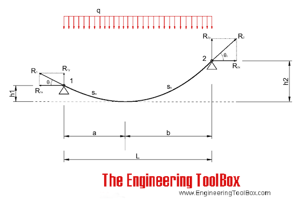
i have a (long) question on the force calculations of an offset load on a horizontal highline.. If I enter my data into a spreadsheet I am creating for teams to have available on a tablet, the force calculations and angle come out different than what it shows here.
for example, load of 400.. 100′ span, V1 and V2 of 20′, H1 of 75, H2 of 25 the load calculations show T1 of 388.1, and T2 of 480.23. The angle at the load here shows 126.41 degrees.
Can you share the math this example is using to calculate the anchor tension for a static load at the offset position? I have tried many different ways of using sin of the angles but I’m having a really hard time with it.. I have another document, Forces Based on Point Loads in a Catenary by Attaway, and I think i’ve read it about 50 times but the functions are a little above my comprehension.. Hope you can help out.
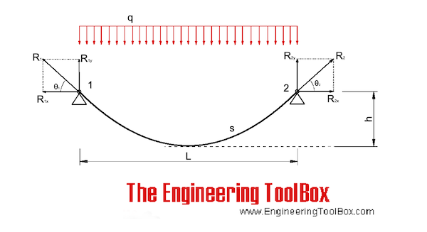
The equations below can also be used for cables only loaded with their own weight as long as the sagging height (h) vs. length (L) ratio is below 0.1.
The calculator below can be used for cables with inclined chords and uniformly loads. The calculator is based on an iterative algorithm where the parable shaped cable is adapted to span L, height h1 and h2 according the figure above. The parable equation estimated below can be used to replicate the shape in spreadsheets or CAD systems.
Some of our calculators and applications let you save application data to your local computer. These applications will - due to browser restrictions - send data between your browser and our server. We don"t save this data.
Stren-Flex® manufactures an extensive line of high quality lifting slings and protective rigging gear to ensure a safe lifting experience. Our nylon and polyester web slings and roundslings are made in the USA and manufactured with care to meet or exceed OSHA and ASME standards. Our Simian® GT roundslings have the highest capacity ratings per color code in the industry and our Simian® Ultra High Performance Fiber roundslings offer advanced strength to weight ratios for extreme heavy lifting. We also offer a wide variety of cargo control tie downs, chain slings, wire rope slings, and rigging hardware.
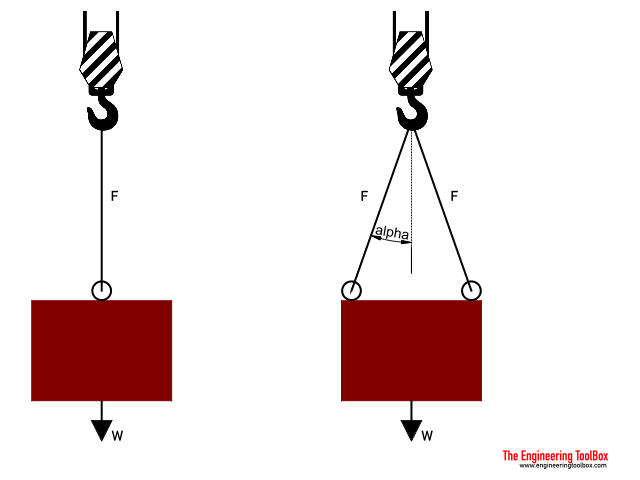
where weight, W, becomes negative since it is directed downwards. By transposing W to the other side of the equation, we can now see that the tension force in the rope is equal to the weight of the object it carries, as also shown above.
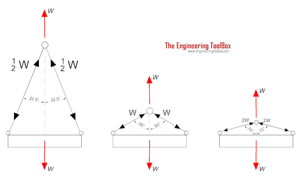
If we use more ropes to lift the object, the total tension force gets divided up into the ropes. The tension force in each rope depends on their angles with respect to the direction of the force it opposes. To further understand this, let us consider another free-body diagram of an object suspended by two ropes, as shown below:
Now all you need to know are the angles of the tension ropes with respect to the horizontal. If an angle from the vertical is given, just subtract this angle from 90°. Doing so will provide you with the angle from the horizontal. However, if you are given other values of angles that may be greater than 90° or even 180°, you might want to check out our reference angle calculator to help you determine the angle you need. After determining the values for the variables in our tension force formulas, we can now solve for the tension forces.
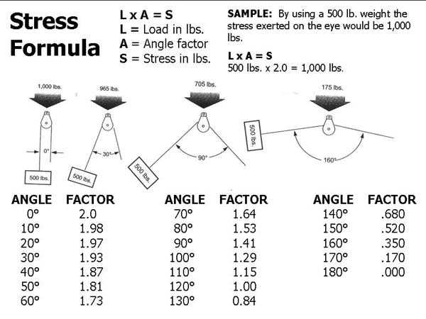
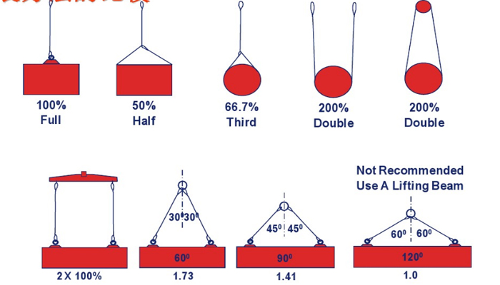
Block Division, Inc., has established through an accredited testing laboratory the capacity at which our products may be safely used. This may be defined as the safe working load limit, a chain or cable rope pulley block load calculation, or a force calculator. The safe working load limit (mechanical advantage) is the maximum load in pounds which should ever be applied, and when the load is applied uniformly and in direct tension to a straight segment of wire rope. By changing the degree of angle between lead and load angle, this also affects the stress on the block. The stress on the eye may be decreased by increasing the angle between the load and the lead angle. See chart 1 and illustration below.

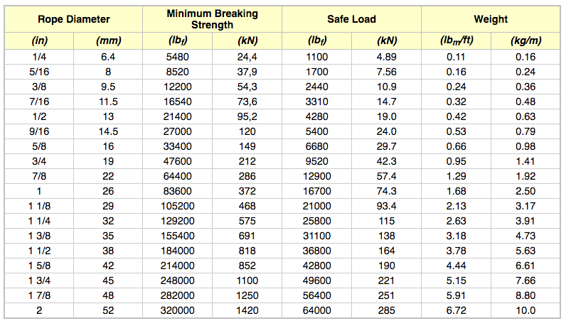
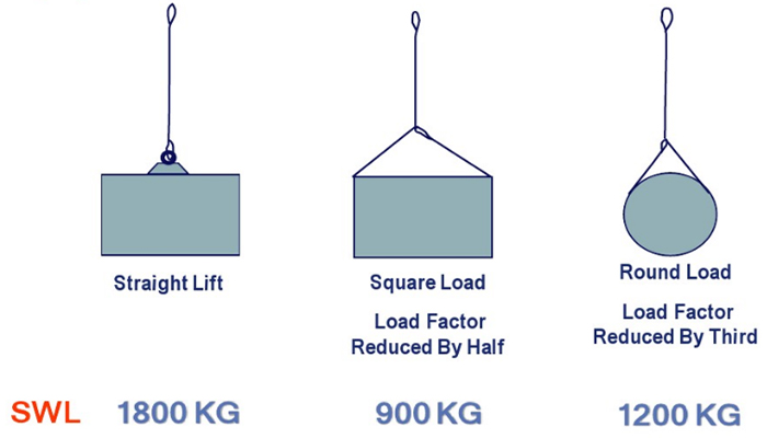
Have you ever wondered how much weight a wire cable can safely hold? It’s surprising how strong wire cables are. Although wire cables often have small diameters and look flimsy, their strength is impressive. Calculating how much weight a wire cable can hold is called a Safe Working Load (SWL), and involves a mathematical formula. The SWL is usually calculated by the manufacturer of the cable and is marked on the packaging to inform consumers. To ensure your safety, always take note of the SWL the manufacturer provides.
SWL can also apply to other lifting devices or components of lifting devices, such as a line, rope or crane. The SWL is also sometimes referred to as Normal Working Load or Working Load Limit. It is the mass that lifting equipment can safely hold without fear of breaking. The SWL or NWL is often a fifth of the Minimum Breaking Strength of the cable, although sometimes other fractions are used, depending on the manufacturer.
To calculate the SWL, you need to know the diameter of the cable or rope. While you may find this on the packaging, you can also calculate it manually by measuring it yourself. Ensure that you enclose all of the strands of rope when measuring the diameter, and measure from the top of one strand to the top of the strand which is directly opposite. If you’re worried about the accuracy of your measurements, conduct your measurements three times at different places on the cable, and use the average of your three measurements as the diameter of the rope.
Once you know the diameter of the rope, you can apply it to the formula, which is SWL = D2 x 8. D represents the diameter of the rope in inches. If you’re working with a 1.5-inch diameter cable, for example, then the formula would be SWL = 1.52 x 8 or SWL = 2.25 x 8. This calculation means the SWL of a 1.5-inch diameter rope is 18 tons.
Take note that most manufacturers will provide you with the SWL for their rope or cable under specific conditions. It’s important to use the SWL the manufacturer gives you. If you’re working with old rope or rope that is worn down, you may want to reduce the SWL of the rope by as much as half, based on the condition of the rope. You can also use the manufacturer’s Breaking Strength of the rope if it is available.

Wire ropes are essential for safety purposes on construction sites and industrial workplaces. They are used to secure and transport extremely heavy pieces of equipment – so they must be strong enough to withstand substantial loads. This is why the wire rope safety factor is crucial.
You may have heard that it is always recommended to use wire ropes or slings with a higher breaking strength than the actual load. For instance, say that you need to move 50,000 lbs. with an overhead crane. You should generally use equipment with a working load limit that is rated for weight at least five times higher – or 250,000 lbs. in this case.
This recommendation is all thanks to the wire rope safety factor. This calculation is designed to help you determine important numbers, such as the minimum breaking strength and the working load limit of a wire rope.
The safety factor is a measurement of how strong of a force a wire rope can withstand before it breaks. It is commonly stated as a ratio, such as 5:1. This means that the wire rope can hold five times their Safe Work Load (SWL) before it will break.
So, if a 5:1 wire rope’s SWL is 10,000 lbs., the safety factor is 50,000 lbs. However, you would never want to place a load near 50,000 lbs. for wire rope safety reasons.
The safety factor rating of a wire rope is the calculation of the Minimum Break Strength (MBS) or the Minimum Breaking Load (MBL) compared to the highest absolute maximum load limit. It is crucial to use a wire rope with a high ratio to account for factors that could influence the weight of the load.
The Safe Working Load (SWL) is a measurement that is required by law to be clearly marked on all lifting devices – including hoists, lifting machines, and tackles. However, this is not visibly listed on wire ropes, so it is important to understand what this term means and how to calculate it.
The safe working load will change depending on the diameter of the wire rope and its weight per foot. Of course, the smaller the wire rope is, the lower its SWL will be. The SWL also changes depending on the safety factor ratio.
The margin of safety for wire ropes accounts for any unexpected extra loads to ensure the utmost safety for everyone involved. Every year there aredue to overhead crane accidents. Many of these deaths occur when a heavy load is dropped because the weight load limit was not properly calculated and the wire rope broke or slipped.
The margin of safety is a hazard control calculation that essentially accounts for worst-case scenarios. For instance, what if a strong gust of wind were to blow while a crane was lifting a load? Or what if the brakes slipped and the load dropped several feet unexpectedly? This is certainly a wire rope safety factor that must be considered.
Themargin of safety(also referred to as the factor of safety) measures the ultimate load or stress divided by theallowablestress. This helps to account for the applied tensile forces and stress thatcouldbe applied to the rope, causing it to inch closer to the breaking strength limit.
A proof test must be conducted on a wire rope or any other piece of rigging equipment before it is used for the first time.that a sample of a wire rope must be tested to ensure that it can safely hold one-fifth of the breaking load limit. The proof test ensures that the wire rope is not defective and can withstand the minimum weight load limit.
First, the wire rope and other lifting accessories (such as hooks or slings) are set up as needed for the particular task. Then weight or force is slowly added until it reaches the maximum allowable working load limit.
Some wire rope distributors will conduct proof loading tests before you purchase them. Be sure to investigate the criteria of these tests before purchasing, as some testing factors may need to be changed depending on your requirements.
When purchasing wire ropes for overhead lifting or other heavy-duty applications, understanding the safety dynamics and limits is critical. These terms can get confusing, but all of thesefactors serve an important purpose.
Our company has served as a wire rope distributor and industrial hardware supplier for many years. We know all there is to know about safety factors. We will help you find the exact wire ropes that will meet your requirements, no matter what project you have in mind.
Basic guardrail components come in a variety of materials and configuration options. It is common for employers to use material available or produced at the worksite. Upright supports may be made from wood, formed metal, pipe, or composites. Wire rope is sometimes used for the top rails and midrails.
Premade guardrails are particularly susceptible to damage if not handled properly when disassembled and stored. Specific handling instructions are typically included in the manufacturer’s recommended procedures for disassembling and storing the guardrail components. If railing components are bent, broken, or missing, the guardrail may not be effective. Damage is more likely to occur if the components are dropped when disassembled, transported in vehicles, or stored in areas not protected from conditions that could cause corrosion or distortion.
Covers for permanent holes are typically built for a specific purpose (e.g., permanent access points, manhole covers, and trap doors) and are only effective when they are properly designed and secured in place.
The hole size and the expected load weight are considered when determining if the plywood is effective for use as a hole cover (see 29 CFR 1926.501(b)(4); 29 CFR 1926.502(i)(1), (i)(2)).
Plywood is susceptible to damage over time from exposure to water, traffic, and heavy loads that may reduce its strength. Some indicators of reduced-strength plywood may include cracks, chips, a warped appearance, a worn surface, de-lamination, and water stains. Expected damage after exposure to water depends on whether the plywood is exterior-grade or interior-grade. The binding agents (i.e., adhesive) used to adhere interior-grade plywood layers degrade more rapidly in a moist environment than do the binders used in exterior-grade plywood. For specific cases, SLTC, in conjunction with the U.S. Forest Service Products Laboratory, can evaluate plywood strength degradation.
When workers are using hauling equipment, the weight of the equipment and its load is concentrated into the smaller area that contacts the ground (e.g., the load in a wheelbarrow will concentrate where the wheel hits the ground – an area of just a few inches in size). Commonly used routes for hauling these loads will experience additional wear and tear to the flooring. Adding a protective layer to the floor along these routes is one way to prevent damage to the flooring from concentrated loads. Typical protective layers may include liquid latex compounds, penetrating oils, sheet plastics, and interlocking membranes.
A warning line system is a barrier erected on a flat or low- sloped roof to warn workers that they are approaching an unprotected roof side or edge (see 29 CFR 1926.500(b); 29 CFR 1926.501(b)(10); Figure 11). A warning line system includes a line (rope, wire, or chain) and supporting stanchions (see 29 CFR 1926.502(f)(2)).
PFAS components will be marked by the manufacturer with pertinent information specific to the equipment, such as warnings, serial/model number, capacity, and the materials used to make the component (see Figure 14). Information (e.g., proper use, maintenance, inspection) about fall protection components is typically provided in equipment manuals.
Many factors can contribute to a workers’ risk of falling from an elevated work area. Examples include precarious work positions, excessive leaning or reaching, improper work practices, unstable structures, trip hazards, slippery surfaces, and distractions.
When guardrails are not an option, personal fall protection equipment is helpful in some situations, but only when properly selected, worn, and attached to an adequate anchor point.
A lanyard is a flexible rope, wire rope, or strap which generally has a connector at each end for connecting the body belt or body harness to a deceleration device, lifeline, or anchorage point (see 29 CFR 1926.500(b)). Some manufacturers offer adjustable length lanyards. Effective lanyards are maintained in a clean, intact condition, and inspected prior to each use for wear, tear, and any obvious distortion or signs that the fall arrest (energy-absorbing) system has been activated (see 29 CFR 1926.502(d)(21)).
Lifelines function as an extension of an anchorage system, allowing an employee to move up and down (vertical lifeline) or back and forth (horizontal lifeline) across a work area. A sliding fitting (rope grab or shuttle) connects to the line and a lanyard connects the worker’s harness to that sliding fitting.
Depending on their geometry and sag angle, horizontal lifelines may be subjected to greater loads than the impact load imposed by an attached component. When the horizontal lifeline’s sag is less than 30 degrees, the impact force imparted to the lifeline by an attached lanyard is greatly amplified. For reference, a 15-degree sag angle amplifies the force approximately 2:1. A 5 degree sag angle amplifies the force approximately 6:1. See 29 CFR 1926 Subpart M, Appendix C for more information.
Even when a PFAS works properly, the fallen worker is still in danger. The worker"s body weight places pressure on the harness straps, which can compress the veins, and cause blood to pool, in the lower extremities and reduce blood return to the worker"s heart (see Figure 17). This condition is called suspension trauma, also known as harness hang syndrome. In medical terms, this results in orthostatic intolerance. If the pressure is not reduced promptly, the worker can lose consciousness within minutes. (See Suspension Trauma/Orthostatic Intolerance, OSHA Safety and Health Information Bulletin.
With proper personal fall protection equipment, training and practice, a fallen worker can take steps to minimize suspension trauma. Self-rescue methods allow a fallen worker to temporarily relieve pressure on the legs or in some cases to even lower himself or herself to the lower level. Self-rescue methods are discussed in detail in Washington Industrial Safety & Health Division"s Fall Protection Responding to Emergencies.
Both a personal fall arrest system and a guardrail system with a minimum 200 pound top rail capacity (when the platform is supported by ropes); guardrail system only (when the platform is supported by the frame structure)
Rope lifeline attaches to an anchorage at the top and hangs vertically down through the work area. Movable rope grab attaches to the rope. Lanyard connects the rope grab to workers’ harness. To move up and down the work area, the worker can slide the rope grab up and down the lifeline, then relock it in place. If the worker falls, the rope grab locks onto the rope to break the fall. This system’s effectiveness depends on how well the worker is trained to reposition the rope grab while moving about. The grab can slide off the end of the rope if the rope is too short, if a knot is not tied near the end of the rope, or if the grab is not installed properly.
The lifeline is wound on a reel and automatically extends or retracts to take up slack in the line as the worker moves about. A sudden extension in the line activates a locking mechanism that typically includes a deceleration device. Some self-retracting lanyards can be set to restrict the distance traveled and so can also function as part of a properly designed fall restraint system.
Thimbles provide a protective interface between the eye of a rope loop and a connector. They are used to prevent pinching or abrasion of the rope. The thimble needs to be firmly seated in the eye of the rope loop.


 8613371530291