
wire rope load calculator in stock
Wire rope is also known by many other names, such as: wire, multi-strand wire, flexible wire, cable, cord, steelcord, etc. but it is essentially a collection of small filaments wound around each other in a manner that largely retains its shape when bent, crushed and/or tensioned.
It is a system for significantly increasing the strength and flexibility of steel wire and is used in almost every important application we see around us. For example: suspension bridges, tyres, brake and accelerator cables (in cars), high-pressure flexible pipes, lifting and rigging cables, electrical conductors, etc. and it comes in many different forms. Fig 2 shows just a very small sample of available designs.
With minor variations, the generally accepted method for designating a wire rope construction in the industry is by describing it numerically. For example:
Whilst "IWRC" wire ropes offer a slightly greater tensile capacity (≈7%) than those with fabric or polymer fillers, the additional strength does not come from the tensile capacity of the core filaments but from improved dimensional stability under load. And whilst they are also much more resistant to crushing, they are stiffer than fibre core ropes and therefore not recommended for applications where tension occurs under bending.
Warrington (Fig 1) is a parallel lay construction with an outer layer comprising wires of alternating large and small diameters, each outer layer having twice the number of wires as the layer immediately beneath. The benefit of this design is to increase packing and therefore strength density, however, unless the different diameter filaments are of the same strength (unlikely), this construction is limited by the strength of the weakest filaments.
Seale (Figs 1 & 2 6x36) is also a parallel lay construction but with the same number of wires in each wire layer. All the wires in any layer are the same diameter. This is an alternative to the Warrington construction, with similar benefits and disadvantages.
Regular lay constructions are used much more widely (than Lang lay) because they have excellent structural stability and less tendency to unwrap under tension (see Rotating vs Non-Rotating below). However, because it has a knobbly (undulating) surface it will wear both itself and any surface over which it is run much more quickly than Lang lay wire rope.
Lang lay constructions have a flatter surface than regular lay constructions giving them better resistance to wear and bending fatigue, especially when made from flattened (elliptical) filaments. They are, however, much less structurally stable and subject to birdcaging if the wire rope is over-bent or twisted against its wrapped direction.
"Regular Lay", multi-strand constructions are normally subject to slightly less rotation under tension (than Lang lay) due to the opposite helical direction of the filaments (within the strands) and the strands (within the rope), however, you can improve their rotation characteristics still further by;
Fillers (Fig 2) may be fabric, polymer or even smaller diameter filaments (e.g. 6x36). Whilst they contribute little to the tensile strength of wire rope, they can significantly; improve performance under bending (fabric and polymer cores only), reduce axial growth, reduce rotation in rotation-resistant constructions, improve structural stability and increase fatigue life.
This filler material should not be included in strength (tensile capacity) calculations, but must be included in those for axial stiffness (extension). If it is ignored, your calculations will reveal excessive extension as the wire rope collapses.
Suspension bridges tend to be constructed from densely packed, single strand plain "Wire Rope" constructions using large diameter galvanised filaments. Little heed is paid to rotational resistance as strength is paramount and once tensioned, they should remain in that loading condition for their design life.
Lifting & winching normally require wire ropes of good flexibility and fatigue resistance. Therefore they tend to be similar to 6x36 but with fibre core instead of the IWRC in Fig 2
Remote operating cables such as hand-brakes and accelerators on cars normally only work in tension so they need to be strong but not necessarily stiff (as they are fully contained in reinforced outer sheaths). These tend to be manufactured from large diameter "TyreCord" or small diameter single-strand "Wire Rope".
Wire rope does not obey Hooke"s law. Therefore, you cannot accurately predict how much it will stretch for any specified force. This unpredictability applies to any section removed from the same manufactured length of cord and even between cords produced to the same specification but by different manufacturers.
CalQlata has decided that the accuracy of axial stiffness (EA) of wire rope falls outside its own levels of acceptability and therefore does not include it in the wire rope calculator. The extension calculated in the Wire Rope calculator (δLᵀ) is based upon the effect of axial tension on packing density. It is therefore important that core material is not ignored when using the calculator to evaluate this characteristic.
Wire rope does not obey Hooke"s law. Therefore, you cannot accurately predict how much it will twist for any specified torque. This unpredictability applies to any section removed from the same manufactured length of cord and even between cords produced to the same specification but by different manufacturers.
CalQlata has decided that the accuracy of torsional stiffness (GJ) of wire rope falls outside its own levels of acceptability and therefore does not include it in the wire rope calculator.
1) No wire rope calculator, whether dedicated or generic, will accurately predict the properties of any single construction under a wide range of loading conditions
2) No wire rope calculator, whether dedicated or generic, will accurately predict any single property for a range of constructions under a wide range of loading conditions
The only wire rope that can be reliably analysed is that which is used for suspension bridges, because; it comprises a single strand, is very densely packed, has negligible twist, contains filaments of only one diameter, is never subjected to minimum bending and every filament is individually tensioned.
There is a very good reason why manufacturers do not present calculated performance data for construction or design proposals, because even they cannot accurately predict such properties and quite rightly rely on, and publish, test data.
During his time working in the industry, the wire rope calculator"s creator has seen, created and abandoned numerous mathematical models both simple and complex. He has gradually developed his own simplified calculation principle based upon his own experience that still provides him with consistently reliable results of reasonable accuracy.
The purpose of CalQlata"s wire rope calculator is to provide its user with the ability to obtain a reasonable approximation for a generic construction, after which, accurate test data should be sought from the manufacturer for the user"s preferred construction.
The calculation principle in the wire rope calculator is based upon changes in the properties of the wire rope that occur with variations in packing density under tension
Bearing in mind the above limitations CalQlata can provide the following assistance when generating (manipulating) the wire rope calculator"s input data and interpreting its output
Alternatively, for wire rope with multiple filament diameters, you need to find an equivalent diameter with the following proviso; you must enter the minimum filament yield stress (SMYS)
It is expected that apart from fillers, all the material in the wire rope will be identical and therefore have the same density, i.e. using different materials will result in less than "best" performance. However, if such a construction is proposed, you can calculate an equivalent density as follows:
It is expected that apart from fillers, all the material in the wire rope will be identical and therefore have the same tensile modulus, i.e. using different materials will result in less than "best" performance. However, if such a construction is proposed, you should enter the highest tensile modulus.
The wire rope calculator simply adds together the total area of all the filaments and multiplies them by the SMYS entered, which represents a theoretical maximum breaking load that would exist if this load is equally shared across all of the filaments and the lay angles have been arranged to eliminate localised (point) loads between adjacent filaments.
If the wire rope has been properly constructed it is likely that its actual break load will be greater than 80% of this theoretical value. However, given the vagaries of wire rope construction, the actual break load can vary considerably dependent upon a number of factors. CalQlata suggest that the following factors may be used to define the anticipated break load of any given construction:
The axial stiffness and strain under load will be affected by this value, hence the reason why the most reliable (predictable) constructions tend to be minimum [number of] strands and single filament diameter. The Warrington and Seale constructions and combinations thereof tend to provide the highest packing density (but lowest flexibility) and there is little to be gained from using these constructions in more than single stranded wire rope as the benefit of high-packing density will be lost with no gain in flexibility.
The anticipated second moment of area of the wire rope at tension "T" due to deformation but insignificant flattening as it is assumed the wire rope will be bent over a formed (shaped) sheave or roller.
The anticipated tensile modulus of the wire rope at tension "T" due to deformation but insignificant flattening as it is assumed the wire rope will be bent over a formed (shaped) sheave or roller.
It is not advisable to induce this bend radius in operation due to uncertainties associated with wire rope construction, especially for dynamic applications. CalQlata suggests that a similar approach to that used for the break load (Fb) above also be applied here, i.e.:
A change in diameter will occur in all wire rope, irrespective of construction, until packing density has reached a limiting value. The value provided in the wire rope calculator is that which would be expected if the construction remains intact at the applied tension "T"
Unreliability of this value increases with complexity in wire rope due to its longitudinal variability and the increased likelihood of premature failure.
The accuracy of this data will range from about ±1% for wire rope with a single strand and a single filament diameter, up to about ±15% for constructions of similar complexity to OTR cord
A change in length of any wire rope will occur due to the fact that the packing density increases with tension. This is not, however, a linear relationship.
This can be an unreliable value as illustrated by tests carried out (by the author) on two pieces of wire rope supplied by the same well-known manufacturer both of which were cut from the same length, varied in tensile capacity by only 1.5%, but the tensile modulus (and strain at break) varied by 34%. Whilst this was an extreme case, significant variations have been seen in wire rope manufactured by a number of manufacturers.
Whilst the wire rope calculator does not calculate axial stiffness (see Calculation Limitations 9) above), CalQlata can suggest the following rule-of-thumb that will provide reasonable results for most constructions at the applied tension "T":
Where: θ = the "absolute" sum of the average filament lay angle and the average strand lay angle⁽²⁾. Note; the angle of twist (θ) will reduce as tension approaches break load.
Whilst the wire rope calculator does not calculate bending stiffness (see Calculation Limitations 8) above), CalQlata can suggest the following rule-of-thumb that will provide reasonable results for most constructions at the applied tension "T":
Low complexity means single strand and single wire diameter. Medium complexity means multi-strand and single wire diameter. High complexity means multi-strand and multiple wire diameters.
The equations below can also be used for cables only loaded with their own weight as long as the sagging height (h) vs. length (L) ratio is below 0.1.
The calculator below can be used for cables with inclined chords and uniformly loads. The calculator is based on an iterative algorithm where the parable shaped cable is adapted to span L, height h1 and h2 according the figure above. The parable equation estimated below can be used to replicate the shape in spreadsheets or CAD systems.

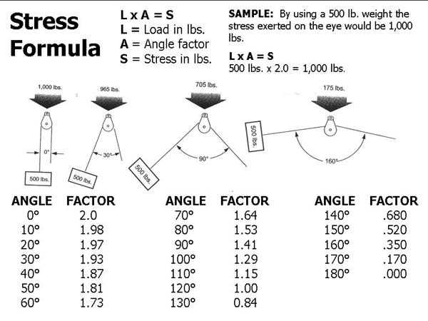
Block Division, Inc., has established through an accredited testing laboratory the capacity at which our products may be safely used. This may be defined as the safe working load limit, a chain or cable rope pulley block load calculation, or a force calculator. The safe working load limit (mechanical advantage) is the maximum load in pounds which should ever be applied, and when the load is applied uniformly and in direct tension to a straight segment of wire rope. By changing the degree of angle between lead and load angle, this also affects the stress on the block. The stress on the eye may be decreased by increasing the angle between the load and the lead angle. See chart 1 and illustration below.
Safe Work Load Limit: This is the maximum load (in lbs.) which can be applied to the Block and which has been established by Block Division, INC. (Load Capacity)

If you are performing calculations involving the load of bridles and basket hitches, it’s important to use a wire rope sling capacity chart and also remember that as a reduction in the horizontal angle of the sling occurs the load imposed upon each leg increases. With bridles consisting of three or more legs, the horizontal angle is measured in the same manner as it is for horizontal sling angles consisting of two legged hitches. Different angles may result if a bridle consists of different leg lengths. The load supported by each leg must be determined based on the location of the center of gravity of the lift in the position of the slings.
At Kennedy Wire Rope & Sling Co., Inc., we provide high quality wire rope sling components and can help you determine the capacity of your wire rope sling arrangement.
The standard choke angle is about 135 degrees when a load is hanging free. However, using a choker hitch to lift internal load can produce a significant bend at the choke. It’s important to reduce a hitches rated capacity when it is used at an angle smaller than 120 degrees. As is evident from a wire rope sling capacity chart, the rated capacity of a wire rope sling must be adjusted when using a choker hitch to turn, shifts, or control the load. The rated capacity must also be adjusted when, in a multi-leg lift, the pull is against the choke.
Using choker hitches at angles of 135° or greater is not recommended due to the instability produced with this arrangement. In addition to consulting with a wire rope sling capacity chart, considerable care should also be taken to ensure that the choke angle is determined and applied as accurately as possible.
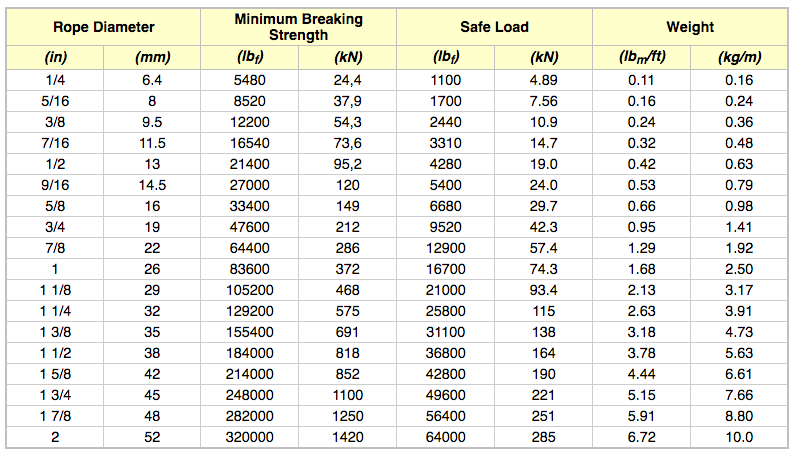
Enter the diameter of the wire rope, in mm, into the calculator to determine the safe working load (SWL). This calculator is for education purposes only, follow manufacturing guidelines for true SWL values.
A safe working load of a wire rope is a measure of the total load or weight that a wire rope can safely support during operation. Values greater than the SWL could result in a failure of the rope.

The end fittings at the load will see the same force as the sling connected to it, and they must also be adequate for their intended use. Please consult Northern Strands order desk for capacities with the use of hardware, or the addition of a top Masterlink.

Hoisting crane has steel rope 2 and has twined load drum 1 above that.The two ends of steel rope 2 all are fixed near the two ends of this load drum 1.When load drum 1 rotates forward, from load drum 1, extract steel rope 2 out.When load drum 1 contrarotation, steel rope 2 is recoiled on the load drum 1.The axle of load drum 1 is connected on lifting/recoil driving engine 2.Rotate this axle of driving through lifting/recoil driving engine 2, forward direction and rotary lifting cylinder 1 oppositely.The driving of lifting/recoil driving engine 2 (control of hand of rotation, rotation begin and stop control from reaching this rotative speed of control or the like) is realized by the craneman.
The a plurality of pulleys that below load drum 1, provide steel rope 2 to twine above that.In hoisting crane shown in Figure 1, placed equalizer pulley 3 in winding (loopback) position of steel rope 2.On each side of equalizer pulley 3, to have placed dead sheave 4 and two removable pulleys (lifting hook pulley) 5,6 around the mode of left and right symmetry of equalizer pulley 3.The suspension hook 7 of Suspended Cargo is connected to removable pulley 5,6.
Because steel rope 2 is extracted out from load drum 1 when load drum 1 forward direction rotates, so the removable pulley 5,6 that steel rope 2 twines above that moves down.Because steel rope 2 is wound on the load drum 1 when load drum 1 contrarotation, therefore removable pulley 5,6 moves up.Along with the rising of removable pulley 5,6 or descend, be suspended on goods on the suspension hook 7 and be raised or reduce.
To be used to detect the load sensor 8 that is applied to the load on the equalizer pulley 3 and be installed in equalizer pulley 3.Load sensor 8 can have desktop type, extruding type, tension force type, amplifier type, bearing type or follow closely type or the like.From load sensor 8 outputs and the corresponding voltage of load.The voltage of exporting from load sensor 8 is applied to rope service-life management devices 10.
Fig. 2 is to draw the time and along the form of the figure of plotted load (with this corresponding voltage of loading) along horizontal shaft; Show during being lifted to it and putting down subsequently of goods, from load sensor 8 data output and that be applied to rope service-life management devices 10.Details about term shown in this Fig will be described after a while.
As stated, hoisting crane will be suspended on goods on the suspension hook 7 and mention, moves and put down subsequently.After mentioning the goods that remains static, very big load just acts on equalizer pulley 3.Himself compare with goods, the load that after mentioning this goods, acts on equalizer pulley 3 is just bigger.Hereinafter will temporarily act on equalizer pulley 3 after mentioning goods bigger load is called " impact load ".The size of this impact load depends primarily on craneman"s operation skill.
When mentioning goods, steel rope 2 is in its state of from load drum 1, having extracted out.Therefore, because impact load has very strong influence to steel rope 2.If impact load is bigger, then to compare with the less situation of impact load, its degree to the damage that steel rope 2 causes is bigger.Compare with the steel rope 2 that does not receive greater impact load continuously, fast more to the damage development ground of the steel rope 2 that receives the greater impact load continuously.
Rope service-life management devices 10 passes through not only to consider to use the number of times of steel rope 2, but also considers the influence of impact load, predicts the replacement time (calculating its life-span) of the steel rope 2 that is using in the hoisting crane.
Fig. 3 shows the transparent view of the outward appearance of rope service-life management devices 10, and Fig. 4 shows the block diagram of the electrical arrangement of rope service-life management devices 10.
The front elevation of rope service-life management devices 10 is provided, and is the display unit 12 with display panel that can videotex at it than top, is the input block 13 with the TIP that comprises numerical key than the lower part at it.Show that on the display panel of display unit 12 screen (being used to import the screen that data are set) is set shields (screen that is used to show the serviceability etc. of hoisting crane) with operating.
With reference to Fig. 5, what on the display panel of display unit 12, shown is provided with on the screen title that shows a plurality of projects that will import (setting).Use input block 13 to import the character that perhaps is used to specify this digital value with the corresponding digital value of items displayed title.With reference to Fig. 6; Operating period of hoisting crane or after, attend display operation state on institute"s operation displayed screen [number of times (remaining operable number of times) (description after a while) that the number of times that the actual payload of the goods of mentioning, steel rope have used (access times of accumulation) and residue are used or the like] at the display panel of display unit 12.
Once more with reference to Fig. 3 and Fig. 4, the input/output end port 14 (invisible Fig. 3) of the voltage that provides from aforesaid load sensor 8 to its input is provided on the back side of rope service-life management devices 10.The input/output end port 14 of load sensor 8 and rope service-life management devices 10 is electrically connected by signal wire (SW) (coaxial cable etc.).
Rope service-life management devices 10 comprises and is used for CPU 11 that the operation of rope service-life management devices 10 is managed as a whole.Above mentioned display unit 12, input block 13 and input/output end port 14 be connected to CPU 11.Be connected to the RAM 15 that also is useful on temporarily stored programme and data of CPU 11 and be used to store ROM 16 that data and program are set or the like.
Fig. 7 and Fig. 8 show to use the data that are provided with of shielding among the ROM 16 that imports and be stored in rope service-life management devices 10 are set.
This is provided with data and comprises the data relevant with hoisting crane and steel rope 2, and with the relevant data of evaluation criteria (for example, being used for confirming the standard of executed load/unload).The data that are provided with shown in Fig. 7 are be provided with data relevant with hoisting crane and steel rope 2.The data that are provided with shown in Fig. 8 are be provided with data relevant with evaluation criteria.
Workload W: it is the maxim (rated value) of the load of the steel rope 2 that is applied in fact to use in the hoisting crane.Under the situation of the hoisting crane shown in Fig. 1, because steel rope 2 is wrapped in the fact on equalizer pulley 3, dead sheave 4 and the removable pulley 5,6, so steel rope 2 has eight drop wires (fall) (load is treated to and is distributed among eight steel ropes 2).If the lifting load (rated load) of supposition hoisting crane is 40 tons, suppose that then the 40/8=5 ton is the workload W relevant with steel rope 2.
The quantity X that rope is sagging: the quantity of its steel rope that comes down to use in the hoisting crane 2, this quantity that is based on the pulley that hoisting crane has obtains, as stated.
1: it is that the point (zone of regulation) on the steel rope 2 is crossed the number of times of pulley during the mentioning and put down (circulation) of goods.Under the situation of the hoisting crane shown in Fig. 1, on each side of equalizer pulley 3, arrange three pulleys (dead sheave 4 and two removable pulleys 5,6).Therefore, when promoting goods, steel rope 2 is crossed pulley three times, and steel rope 2 is crossed pulley three times (six times altogether) when putting down goods.Therefore, to cross the number of times of the pulley (bending) of the hoisting crane shown in Fig. 1 be six times to steel rope.
2: it is that the point (zone of regulation) on the steel rope 2 is crossed the number of times of load drum 1 during the mentioning and put down (circulation) of goods.Under the situation of the hoisting crane shown in Fig. 1, there is a load drum 1, therefore in a circulation, steel rope 2 is crossed this cylinder once.Therefore, to cross the number of times of the cylinder (bending) of the hoisting crane shown in Fig. 1 be once to steel rope.
aBe used to through Niemann formula calculating steel rope 2 operable residue degrees (life-span of estimation) that use description after a while and the number of times (life-span minimizing value) that steel rope 2 has used.Usually, the pulley that has a U-lag generally is used for the pulley that hoisting crane uses.
Steel rope coefficient b: it is through using the Niemann formula to calculate the employed value of number of times (coefficient) that steel rope 2 operable residue degrees and steel rope 2 have used.Structure according to the steel rope 2 that uses is come regulation steel rope coefficient b (for example, this steel cord structure is " ordinary lay " or " afterturn in the same way ").
3: they are to be used for being similar to the mode of top mentioned rope coefficient b, proofread and correct the value (coefficient) of the number of times that steel rope 2 operable residue degrees and steel rope 2 used according to the structure of steel rope 2.The correct-by-construction coefficient k
3It is another value (coefficient) (shape of cross section [no matter cross-sectional plane is circle or non-circular (line of peculiar shape)] of forming the rope of steel rope 2 is no matter whether the surface of steel rope 2 is smeared or the like) that meets the structure of steel rope 2.
Load detection load: it is the load of the lifting of goods (loading) that has been used for having confirmed the hoisting crane executed.If detect the load that is equal to, or greater than this loading detection load, then definite hoisting crane has been mentioned goods.
The unloading detection load: it is to be used to confirm that after hoisting crane was mentioned goods, this goods was put down the load of (unloading).If detect load, confirm that then this goods is put down less than this unloading detection load.
Load obtains time gap: the specified time section that the time of mentioned loading detection load begins above obtaining is that load obtains time gap, and is as shown in Figure 2.Be equal to, or greater than the load that loads detection load if detect; Detect load, in addition, comparing the longer time with load acquisition time gap less than the unloading detection load; Detect continuously and be equal to, or greater than the load that loads detection load and be equal to, or greater than the unloading detection load; Then definite hoisting crane has been carried out individual task, promptly by promoting, transport and put down subsequently the sequence of operations (circulation) (that is, having satisfied the loading and unloading standard) that goods constitutes.
Load reads type: use load in the average computation time gap to calculate the load (actual payload) of the goods that hoisting crane promotes.With reference to Fig. 2, the average computation time gap is from the acquisition time passage specific time that loads detection load (average delay time at interval) time of obtaining afterwards at interval, and obtains the period that time that time gap finishes finishes at load.Can select " instantaneous " perhaps " on average " read type as load.If selected " instantaneous ", time that then will be when the average computation time gap finishes (its with load obtain time that time gap finishes identical) detected load, the load (actual payload) of the goods of mentioning as hoisting crane is handled.If selected " on average ", the load (actual payload) of the goods that then will mention as hoisting crane at the aviation value of the load of the detection in the average computation time gap is handled.
Average delay time is at interval: as stated, it is from loading the acquisition time of detection load, and obtains the time gap (with reference to Fig. 2) that time that time gap finishes finishes at load.Above mentioned impact load (peak value) drop on average delay time at interval within.
End-of-life preparation warning condition: whether it is provided with and when the steel rope 2 operable residue degrees of predicting (residual life of estimation) reach certain percentum of new steel rope 2 operable residue degrees (initial lifetime), gives a warning.For example, 20% end-of-life preparation warning condition means, when the residual life of steel rope 2 reach initial lifetime 80% the time, give a warning.Can send this warning through warning tones or the demonstration that on display unit 12, appears with coming sense of hearing ground or vision.
Loading above normal capacity 1-3: when the actual payload of detected goods surpasses the lifting load (rated load) of hoisting crane, also can give a warning.Loading above normal capacity 1-3 is the load when sending this warning.Can send the warning relevant in a plurality of stages (rank) with loading above normal capacity.For example, be under 40 tons the situation,, then to give a warning at the lifting of hoisting crane load if the actual payload of detected goods is equal to, or greater than 45 tons.Through the actual payload according to detected goods be equal to, or greater than 45 tons and less than 50 tons, be equal to, or greater than 50 tons and less than 55 tons and be equal to, or greater than 55 tons various situation and change the demonstration on warning tones (perhaps volume) or the display unit 12; Which come to have used level other loading above normal capacity (that is the concrete load class of the goods of crane) to operator"s untill further notice.
Coefficient of correction: its be used to proofread and correct according to above the value (coefficient) of size (that is, impact load surpasses the percentum of the actual payload of goods) number of times definition, that steel rope 2 has used of mentioned impact load.In this embodiment, be equal to, or greater than under 110% the situation of actual payload sensing impact load, carry out the processing of using this coefficient of correction to proofread and correct the number of times that uses steel rope.To describe after a while and use this coefficient of correction to proofread and correct the details of the processing of the number of times that uses steel rope.
Before being placed on steel rope 2 in the hoisting crane and hoisting crane operate; Relevant with hoisting crane and steel rope 2 data (Fig. 7) that are provided with that rope service-life management devices 10 uses storage among the ROM 16 are calculated steel rope 2 operable residue degrees (life-span of estimation) under the initial condition.
In this embodiment, described and used Niemann (G.Niemann) formula in known up to now a plurality of computing formula, calculated the operable residue degree of steel rope (life-span of estimation).Through the mode of example, at " Wire Rope Handbook " (steel rope handbook editorial board, Nikkan Kogyo Shimbunsha; Publish March 30 nineteen ninety-five; The 352-352 page or leaf) and " All About Wire Rope (Last Volume)-The Road to Safety " (association of industry and commerce of shell mound, the iron and steel manufacturing activates research association, association of industry and commerce of shell mound; Publish the 153-158 page or leaf July 25 nineteen ninety-five) in the details about the Niemann formula has been described.
The Niemann formula is suc as formula shown in (1).Based on the Niemann formula, calculate steel rope 2 and cross the times N of pulley up to its fracture
Next, calculating steel rope based on following formula (2) coefficient safe in utilization crosses pulley and bears the times N of 10% breakage up to it
2Should be noted in the discussion above that " 10% breakage " is the notion of using when considering safety.When steel rope ruptures fully, think that breakage is 100% breakage, and with " 10% breakage " be assumed to complete breakage 1/10 damage state based.
Next, consider tired differential based on the steel rope formation, and based on following formula (3), utilization structure coefficient of correction K
2It is the coefficient that rope structure determined according to the steel rope 2 that uses; It is scheduled in accordance with rope structure.With the correct-by-construction coefficient k that is stored in advance among the ROM 16
Remove this limit number of bends N through using to each hoisting crane circulation (mention, move and put down subsequently goods) steel rope 2 crooked number of times
1The number of times of these pulleys is crossed in expression to each circulation steel rope 2.Use the numerical value of before having imported (setting), as shown in Figure 7 based on crane structure (quantity of pulley).
Bending based on each place of supposition steel rope in these pulleys and cylinder is compound and fatigue accumulation, calculates this steel rope 2 operable residue degrees.According to following formula, pulley mentioned above the use can use cycle number N
As next will describe, according to the crane operation situation (the existence of considering aforesaid impact load or do not exist with and size after), reduce the 2 operable residue degree N of steel rope under initial condition that obtained
Fig. 9 shows the diagram of circuit of flow process of the operation of rope service-life management devices 10.Figure with reference to the load data shown in Fig. 2 describes this diagram of circuit.
When manipulating crane, follow the voltage of the load of goods from load sensor 8 output, and it is offered rope service-life management devices 10.The load data (magnitude of voltage) (with reference to Fig. 2) that load sensor 8 is provided is stored among the RAM 15 of rope service-life management devices 10 (step 31).
At first, judge whether to satisfy load/unload standard (step 32).This is the purpose that is used for the life-span management of (operation cycle is to constitute by mentioning, moving and put down goods) execution steel rope 2 under the situation that hoisting crane is finished the work basically.
Use the normal data (data are set) shown in Fig. 8 to judge whether to satisfy the load/unload standard.With reference to Fig. 2; If detect the load that is equal to, or greater than said loading detection load, detect load, in addition less than said unloading detection load; Comparing the longer time with load acquisition time gap; Detect the load that is equal to, or greater than this loading detection load and is equal to, or greater than this unloading detection load continuously, then confirmed hoisting crane executed individual task, i.e. sequence of operations (circulation) (step 32 " being ").
For example, though even cause under the situation that suspension hook 7 waves in the influence owing to wind, load sensor 8 is output voltage also, in this case, does not satisfy the load/unload standard.If the load data from load sensor 8 does not satisfy the load/unload standard, then rope service-life management devices 10 is not carried out any specific processing (step 32 " denying ").
If load sensor 8 provides the load data that satisfies the load/unload standard, judge then whether the maxim (peak value) (impact load) that comprises in this load data surpasses 110% (step 33) of actual payload.As stated, read the type place at load and select under the situation of " instantaneous ", actual payload is the ubiquitous load that detects when the average computation time gap finishes.If selected " on average ", then actual payload is the aviation value of detected load during the average computation time gap.
If impact load is equal to or less than 110% of actual payload, think that then impact load does not influence (that is, not having impact load) (step 33 " denying ") to steel rope 2.
In this case, control advances to the general processing (being used to calculate the processing of operable residue degree) (step 35) that is used to deduct the number of times that this rope uses.
At first,, use and calculate steel rope 2 operable residue degree N to (5) according to formula (1) based on the actual payload that load data obtained from load sensor 8
(for example, having the structure shown in Fig. 1 if the lifting of hoisting crane load is 40 tons and this hoisting crane, then workload W=5 ton) (it is based on the drawing stress σ that uses in the supposition Niemann formula (with reference to Fig. 7)
tUnder the situation of (=W/A), lifting that hoisting crane can be sling load (rated load)), mentioned 2 operable residue degree N of steel rope under initial condition above calculating
xOn the other hand, exist with promoting load and compare, the load of the actual goods that promotes is the situation of light (perhaps heavier) more.For example, if 40 tons of hoisting cranes are handled 40 tons of goods, then this is the disposable use of supposition steel rope 2.But if handle compare lighter goods (for example, 30 tons) with 40 tons, then this is that supposition is compared use still less with the disposable use of steel rope 2.
RemainWith load (actual payload) that promotes and access times (as long as the basic work of hoisting crane execution up to now; Just calculate the accumulated value of the number of times that this steel rope uses) or the like, be presented at (step 36 on the display panel of display unit 12 of rope service-life management devices 10 together; With reference to Fig. 6).
On the other hand, if impact load surpasses 110% of actual payload, then steel rope 2 is treated to the damage (step 33 " being ") that receives the conflict load.
1The value that multiplies each other and obtained with the coefficient of correction of the size that meets impact load (coefficient that surpasses unit value).
Be provided with the coefficient of correction of the size that meets impact load in advance, and it is stored among the ROM 16, as shown in Figure 8.For example, when impact load be actual payload 115% the time, with the access times H of steel rope
1In the lifting capacity of considering instantaneous application and under the situation of the lifting capacity after removing impact load, use the Niemann formula to seek the coefficient of correction of the size that meets impact load.
Impact load is big more, and the value that then is used as coefficient of correction is with regard to bigger (with reference to Fig. 8).Therefore, impact load is big more, then the access times of this steel rope (life-span minimizing value) H
RemainThe time, judge whether it has reached the access times (step 37) before end-of-life of setting.Based on the end-of-life preparation warning condition that is provided with in advance, come the access times (with reference to Fig. 8) before end-of-life of calculating and setting.(in fact, can calculate this value in advance, and subsequently it is stored among the ROM 16).For example, if end-of-life preparation warning condition is 20%, then 80% of steel rope 2 operable residue degrees value (that is, through multiply by 0.8 value that obtains) becomes the access times before end-of-life of said setting under initial condition.If the steel rope that calculates 2 operable residue degree H

Typically the diameter of halyards and sheets is determined by clutches, cleats and blocks on board of your ship. If you are into yacht racing or rigging a new boat, it can be good to calculate the minimum required breaking load of sheets and halyards in order to reduce weight of ropes onboard. Calculating the required breaking load is a more precise approach for determining the diameter of sheets and halyards.
It is a good idea to build in some safety margin in your calculations. Often a safety factor of 4 is used, which means that a rope will receive a workload of only 25% of the breaking load. This is so called Safe Working Load. In practice, however, sails are usually reefed or the boat is in a safe harbour before a rope is loaded to its maximum. That is why we use a safety ratio for cruising yachts of 2 and even 1.5 for racing yachts.
Bear in mind that the weakest link counts. A splice typically reduces the strength by 5-10% but a knot can take off 50% of the strength. For these calculations we assume that the ropes will be spliced.
For halyards and genoa sheets you can easily calculate the breaking strength by multiplying your sheet size in square meters with 30 (for spinnakers take 13). This allows you to handle your sails still at 7 Bft (41-47knots). We have done the maths for you in the table below. Loads can vary slightly for e.g. catamaran, but variations are usually covered by the safety factor.
For halyards with a 1:2 purchase, you can divide the breaking strength by two. Please note that clutches, cleats, blocks and shackles still bear the full load though!
If the purchase on the mainsheet is four, the load on the mainsheet is divided by four. But note that the forces applied on the mainsheet travellers and blocks will stay the same!
To calculate loading on a genoa lead car, the deflection of the sheet should be taken in account. Most #1 genoas will deflect about 45° whilst a #3 genoa may deflect 75° or more.


 8613371530291