
pulling unit vs workover rig quotation

This website is using a security service to protect itself from online attacks. The action you just performed triggered the security solution. There are several actions that could trigger this block including submitting a certain word or phrase, a SQL command or malformed data.
We like to throw around “blog ideas” over here at Croft to help my fellow blog partner, Amy and I have a new fresh blog every week. We try to keep our readers up to date with both the new and the old. Someone threw out the idea of writing about a workover rig. Still being new to the industry, I snatched this topic up because I simply wanted to learn more about it myself! My main focus for this blog is simply discussing what is a workover rig and why it is important.
First off, maybe you know a workover rig by a different name. They can be called completion wells or pulling units. I just want to try to avoid any confusion! I am going to give Wikipedia’s definition first and then break it down to layman’s terms for those of you who don’t quite understand what the Wiki is trying to say (Like me). According to Wikipedia, “The term workover is used to refer to any kind of oil well intervention involving invasive techniques, such as wireline, coiled tubing or snubbing. More specifically though, it will refer to the expensive process of pulling and replacing a completion.” Let’s break down some of that Terminology…
Snubbing: This method is used in more demanding situations when wireline and coiled tubing does not offer the strength and durability needed. Snubbing runs the bottom hole assembly on a pipe string using a hydraulic workover rig.
So basically, the purpose of a workover rig is to replace a well with a fresh completion. This may have to happen due to the well deteriorating or the changing of reservoir conditions. This is performed if a well completion is unsuitable for the job at hand. An example of the well deteriorating is the equipment may have become damaged or corroded such as production tubing, safety valves, electrical pumps, etc. An example of the changing of reservoir conditions maybe if the flow of a well has decreased over time. If this happens, when the well was originally drilled, it was fit for tubing that was big enough for a higher flow of oil and gas. As the flow decreased, smaller tubing is now needed.
For a workover to take place, a well must be killed or in other words, stop the flow of oil or gas. This is an intense procedure for a workover to take place, so they are planned long in advance.
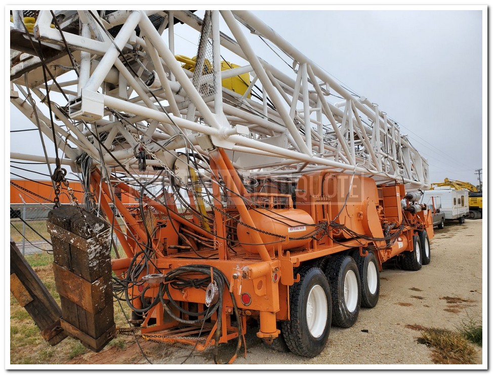
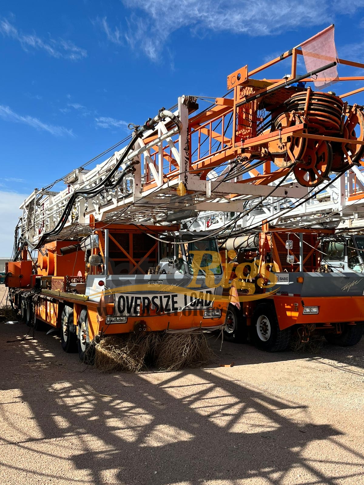
Well Service | Workover Rigs - 844/80 Double drum draw works. looks to be recently rebuilt. Has new Lebus Grooving on Tubing Drum. Comes w/ 250 HP 2 speed jackshaft/RA BOX. More Info
Well Service | Workover Rigs - CARDWELL KB200B Freestanding Oilfield Workover Rig / Service Rig / Pulling Unit, Service Rigs, Used Cardwell KB200B Freestanding Service Rig, 5 Axle Carrier, Detroit 8V71... More Info
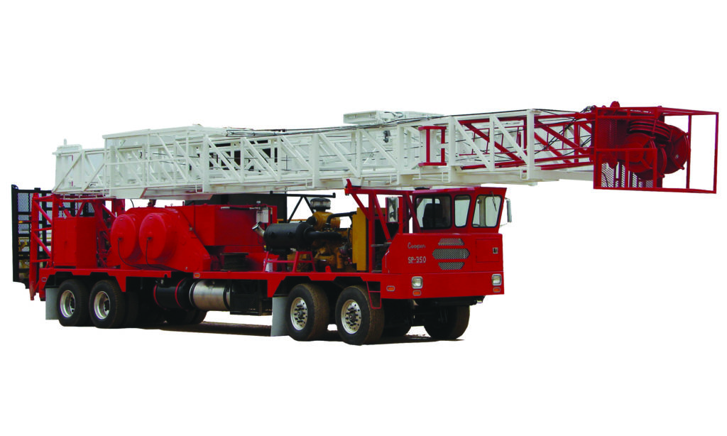
Well Service | Workover Rigs - WELL SERVICE RIG - COOPER 350 Well Service Unit p/b DETROIT 8V-92 Diesel Eng, ALLISON 750 Trans, 42X12-38x8 DRAWWORKS w/dual disc assist, 97â 200,000# Telescoping M... More Info
Well Service | Workover Rigs - CROWN 350 SERIES -- SERVICE KING 104" 205,000# DERRICK, CAT3406, ALLISON 5860,38X10 DOUBLE DRUM DRAWWORKS, CROWN SHEAVES REBUILT 2013 MAIN26âX4,SANDLINE 22â, NE... More Info
Well Service | Workover Rigs - 2008 Crown/Cabot 1058 Service unit mounted on 4 axle carrier w/Detroit 60 Power. New 5860 Drop Transmission. 72" Double rod/single tubing Derrickmast 125000# Rig is in Ex... More Info
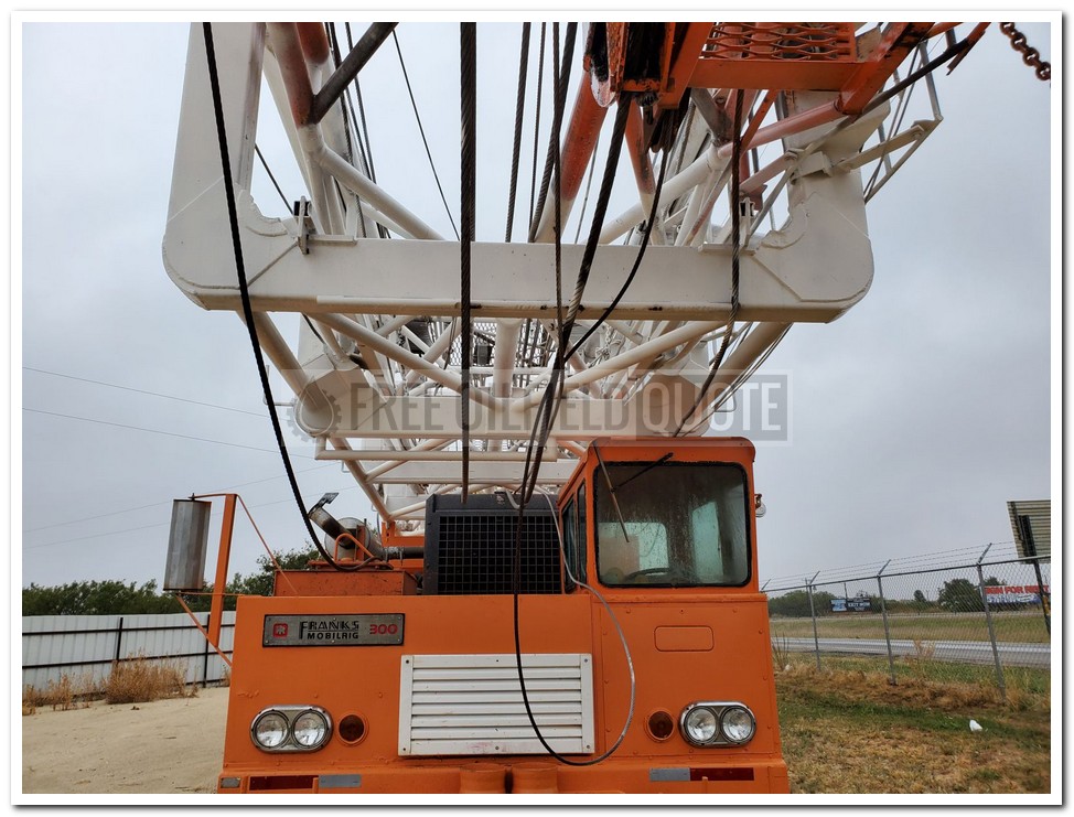
Well Service | Workover Rigs - WELL SERVICE RIG - FRANKS 1287-160-DTD-HT D/D Well Service Unit p/b DETROIT 8V-71N Diesel Eng, ALLISON CBT-4460-1 Trans. SERVICE KING 96" 180,000# Hydraulically Raised & ... More Info
Well Service | Workover Rigs - FRANKS 300 D/D 1287 w/hydromatic brake, Well Service Unit p/b DETROIT 8V-71 Diesel Eng, ALLISON 750 Trans, (Reman Dec 2011) FRANKS 96âH 150,000# Tri-Scope Telescopin... More Info
Well Service | Workover Rigs - FRANKS 658 D/D Well Service Unit p/b CAT 3406 Diesel Eng, ALLISON HT-750 Trans, FRANKS 96âH 180,000# 4-Leg Telescoping Mast, Hydraulically Raised & Scoped w/4-Sheave... More Info
Well Service | Workover Rigs - FRANKS 658 D/D Well Service Unit p/b Series 60 Detroit Diesel Eng, ALLISON 5860 Trans, 102âH 225,000# (on 4 line) Telescoping Mast, Hydraulically Raised & Scoped, Db... More Info
Well Service | Workover Rigs - IDECO H35 96̢۪ 210,000 MAST, DETROIT 60 SERIES ENGINE, ALLISON 5860 TRANSMISSION, REFURB 2005, IDECO DERRICK REPLACED WITH NATIONAL DERRICK, TUBING DRUM CON... More Info
Well Service | Workover Rigs - IDECO RAMBLER H-35 Oilfield Workover Rig / Service Rig / Pulling Unit, Service Rigs, Used Ideco Rambler H-35 workover rig / service rig / pulling unit, 4 axle carrier, De... More Info
Well Service | Workover Rigs - 2015 INTERNATIONAL PAYSTAR 5900 Flushby Unit. C/w 2003, Refurbished in 2015, Western Fab Ltd. flushby unit, s/n 03-09-1008, 50 Ft. Mast height, 50,000 lb. pull rating, fr... More Info
Well Service | Workover Rigs - 2005 KENWORTH T800 Flusby Unit. C/w Lash Ent. flushby unit, 47 ft mast, slant compatible, 3x5 Gardner Denver triplex pump, 5000 psi, 2005 Advance 8m3 tank, TC 406 code, P... More Info
Well Service | Workover Rigs - 2003 KENWORTH T800 Flushby Unit. c/w Online flushby unit, 47 ft. mast, slant compatible, Pullmaster HL25 wotking winch, Pullmaster PL5 catline winch, 2002 wabash two comp... More Info
Well Service | Workover Rigs - 2005 KENWORTH T800B Flushby Unit. c/w Online flushby unit model 50-50, s/n 24641, 40 ft. mast,Salnt compatable, Pull master HL25 and PL5 winch, Gardner Denver 3x5 triplex... More Info
Drilling calls for complex, carefully engineered equipment — and inevitably this equipment can wear down over time and require replacement. That’s where a workover rig comes in. Workovers are among the most expensive and complicated tasks in the drilling industry, so here are a few things you should understand about them.
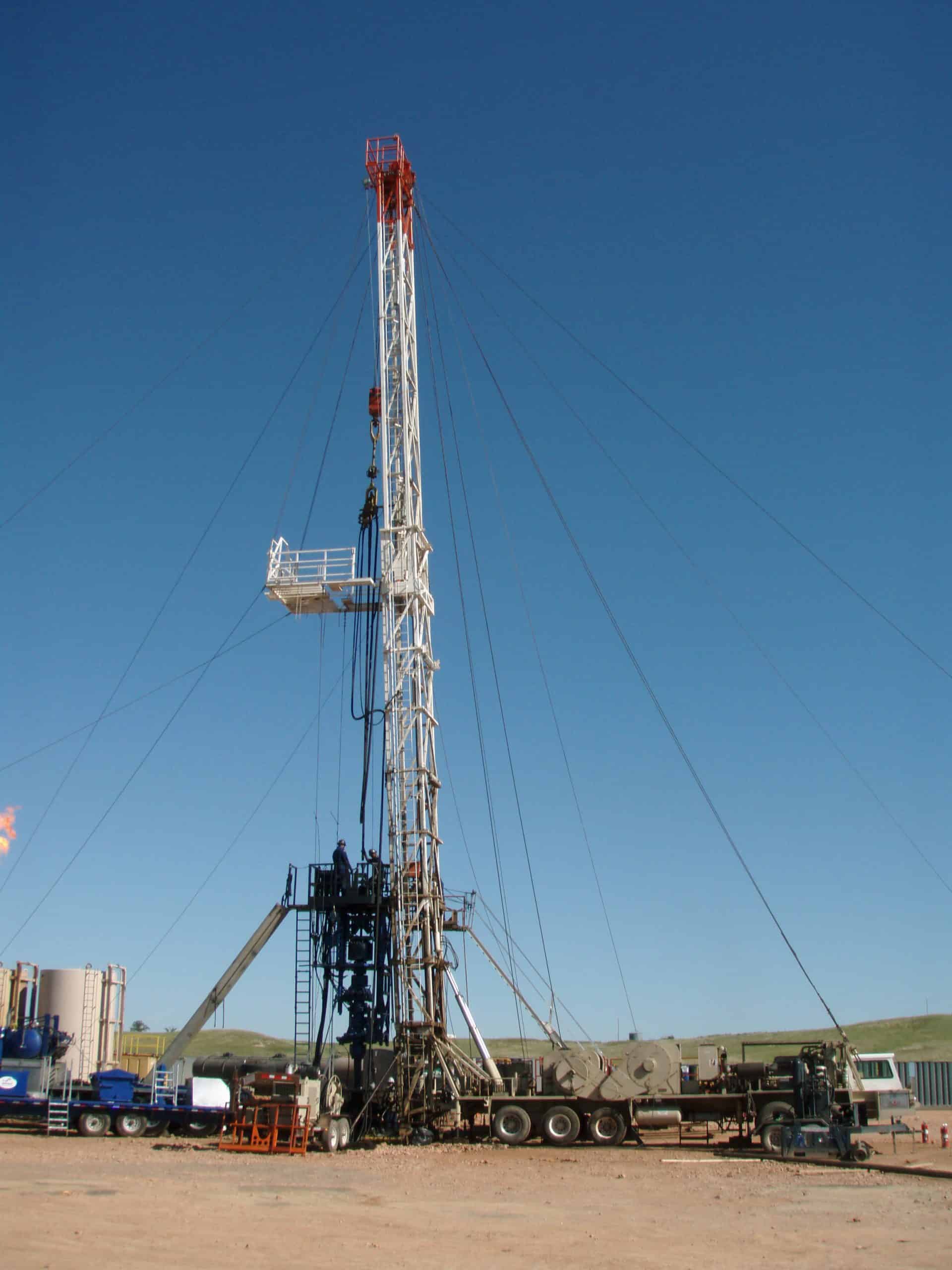
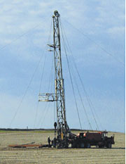
A workover is a complex maintenance task that involves pulling completion hardware out of a well in order to extend the life of the well. A workover rig is a specially designed rig that makes it easier to take out or insert tubing into a well.
To complete a well servicing, the well is first killed. This halts the flow of fluids in the reservoir. The wellhead and flow line will then be removed and the completion hardware will begin to be pulled out of the well using the workover rig. Replacement parts will then be lowered into the hole accordingly.
Because workovers are involved in time-consuming processes, through-tubing workovers might be initiated, which can occur without forcing teams to kill a well and do a full well servicing. This might be considered first before deciding on a full well servicing.
A workover rig is needed when a well is no longer suitable for the drilling job it was originally built for. Maybe the production tubing has incurred damage over time or downhole tubing has stopped functioning correctly. Or perhaps the contents of the reservoir that the tubing is drawing from has changed and requires adjusted tubular components. In any case, the well is unable to perform efficiently and could even compromise the safety of those working on the well. At that point, its components must be replaced and a workover rig must be constructed.
The use of a Snubbing Unit is not only already providing cost effective technology for a wide range of Drilling and Well Servicing applications but also has the potential for providing an alternative way to optimally develop future fields.
Present Snubbing and Hydraulic Workover applications include the undertaking of remedial well work without resorting to the use of kill fluids or lost circulation material and the performing of conventional tubing replacement workovers Snubbing well intervention operations are also now routine where coiled tubing operations are not feasible due to well bore geometry or length and should be considered where platform facilities are unable to handle the weights of larger coiled tubing reels.
Historically, workovers performed through existing tubing ("through-tubing workovers") have been undertaken with wireline or coiled tubing equipment, often supported by the use of a derrick equipment set. Snubbing systems are now performing similar work and are proving to be far more versatile than wireline coiled tubing and conventional workover rigs with the additional ability of being able to run and rotate tubulars while there is pressure on the well. Although certain workover situations will still call for wireline coiled tubing or workover rigs, there are now many situations where a Snubbing Unit is the logical choice. In principle, all of the downhole work that can be carried out by standard rig or through-tubing workover equipment can also be completed by Snubbing Units, with the (current) exception of running large >10 3/4") tubulars.
Future applications for the technology include the horizontal side-tracking of existing wells (which could be performed conventionally or underbalanced). Such operations can either be undertaken through the existing tubing or, where such operations are not deemed feasible, the Snubbing Unit can be used to pull the existing completion prior to the side-track and used for the subsequent running of the liner and completion after drilling.
The term workover is used to refer to any kind of oil well intervention involving invasive techniques, such as wireline, coiled tubing or snubbing. More specifically, a workover refers to the expensive process of pulling and replacing completion or production hardware in order to extend the life of the well.
Workovers rank among the most complex, difficult and expensive types of wellwork. They are only performed if the completion of a well is terminally unsuitable for the job at hand. The production tubing may have become damaged due to operational factors like corrosion to the point where well integrity is threatened. Downhole components such as tubing, retrievable downhole safety valves, or electrical submersible pumps may have malfunctioned, needing replacement.
In other circumstances, the reason for a workover may not be that the completion itself is in a bad condition, but that changing reservoir conditions make the former completion unsuitable. For example, a high productivity well may have been completed with 5½" tubing to allow high flow rates (a narrower tubing would have unnecessarily choked the flow). Some years on, declining productivity means the reservoir can no longer support stable flow through this wide bore. This may lead to a workover to replace the 5½" tubing with 4½" tubing. The narrower bore makes for a more stable flow.
Before any workover, the well must first be killed. Since workovers are long planned in advance, there would be much time to plan the well kill and so the reverse circulation would be common. The intense nature of this operation often requires no less than the capabilities of a drilling rig.
The workover begins by killing the well then removing the wellhead and possibly the flow line, then installing a B.O.P commonly known as a blowout preventer, then lifting the tubing hanger from the casing head, thus beginning to pull the completion out of the well. The string will almost always be fixed in place by at least one production packer. If the packer is retrievable it can be released easily enough and pulled out with the completion string. If it is permanent, then it is common to cut the tubing just above it and pull out the upper portion of the string. If necessary, the packer and the tubing left in hole can be milled out, though more commonly, the new completion will make use of it by setting a new packer just above it and running new tubing down to the top of the old.

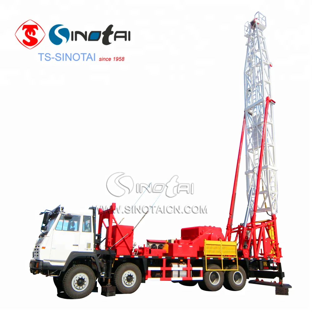
Inserting and pulling up pipe tubing from oil wells is a precise and challenging job that not every rig is up for. That’s why you need a mobile workover rig from Dragon to get it done right every time. Our workover rigs are state-of-the-art and ready to tackle even the harshest conditions. A workover rig is perfect for site preparation while a standard mobile oil rig can handle a variety of piping tasks. Need workover rig parts, or service on another mobile rig? Dragon has that covered with our parts selection, too. View all of our workover rigs and other drilling rigs today.

Workover rigs, also called pulling unit rigs, are specialized oil rigs set up for inserting or pulling pipe tubing in and out of wells. Workover crews are called when an oil well has been drilled, is undergoing repair or is being retired, as indicated by Schlumberger.
These crews are relatively small compared to other rig crews and consist of tool pushers, operators or relief operators, derrick men and floormen or roughnecks. The average workover rig salary overall was $65,039 as reported by Simply Hired in 2022. Available workover rig jobs and descriptions can be found on the Rigzone website.
The acting supervisor on a workover rig is called the tool pusher. The main task of a pusher is to hire, fire and supervise contracting work crews. When contractors have an issue on site, the first person they report concerns to is the tool pusher. Pushers need to have an intimate knowledge of how each and every part of a rig works, both individually and as an overall part of the drilling operation as a whole.
If equipment fails or needs to be reordered, the tool pusher talks with suppliers to get the right parts out on site with a minimum of downtime for the rig. The pusher is responsible for the overall safety of a rig. If the tool pusher has any safety concerns, he has the power to halt production until the concern is resolved.
The operator/relief operator is next in order of responsibility to the tool pusher on a workover rig. The main task of an operator is to control the crane and derrick that hauls pipe in and out of the bored well. In smaller crews, the operator is also the one who drives the rig truck. When laying pipe into a well, the operator directs the truck or derrick to the optimum spot next to the bore opening.
The operator then instructs the derrick hands and roughnecks where to place the bore pipe for easy access by the crane or by hand-loading methods. During a well breakdown or repair, the operator directs the crew hands in storage of extracted pipelines. Because the operators work most closely with derrick hands and roughnecks, they are typically responsible for selection and maintenance of their immediate workover rig crew.
In the pulling unit rig crew hierarchy, the derrick hands come after the operator/relief operators. The main responsibility of a derrick hand is everything that is above ground on the rig. During laying operations, derrick hands assist the operators/relief operators in inserting boring into the well. During repair or breakdown, they assist the operator in pulling pipe out of the well and storing it properly.
In between laying, derrick hands have other responsibilities as well, depending on the size of the crews. In smaller crews, Derrick hands also see to the maintenance of the rig-based electric and diesel generators necessary to power rig equipment.
At the bottom of the pulling unit rig crew in terms of seniority is the floorhand or roughneck. The main task of a roughneck is to perform any kind of tasks asked by either the derrick hand or the operator. These tasks can range from assisting with laying new pipe or removal of old tubing, general construction, to moving new equipment, such as generators. Most crew members on a work-about start their career as a floorhand or roughneck before working their way up to more senior positions.

Manufacturer of standard & mobile rigs & carriers for oilfield applications. Includes well servicing from 14,000 ft. to 22,000 ft., workovers from 10,000 ft. to 16,000 ft. & drilling from 6000 ft. to 10,000 ft. Specifications include brakes range from 28 in. dia. x 8 in. wide to 42 in. dia. x 12 in. wide, barrels from 12 3/4 in. x 38 in. to 18 in. x 43 in., chains from 1 1/4 in. to 1 3/4 in., clutches of 24 in. with single & 2 plate air friction outboards, shafts of 5 in. dia. to 6 1/2 in. dia. & gross weights from 63,200 lbs. to 115,000 lbs. Also includes forged steel, demountable options, mufflers with spark arrestors, dry type air cleaners, transmissions with torque converters, water splash brake cooling & up to 6 axles.

After an oil drilling rig drills a well and installs the well casing, the rig is dismantled and removed from the site. From that point on, a mobile repair unit, or workover rig, is typically used to service the well. Servicing includes, for example, installing and removing inner tubing strings, sucker rods, and pumps. This is generally done with a cable hoist system that includes a traveling block that raises and lowers the aforementioned tubing strings, sucker rods, and pumps. [0001]
U.S. Pat. No. 4,334,217 describes a system for monitoring the movement of a travelling block on a drilling rig. As described in the "217 patent, the traveling block can be raised or lowered beyond a safe limit. This is called “crown out” if the traveling block reaches its upper most safe position, and “floor out” if it reaches its lower most safe position. Crown out/floor out can result in equipment damage and/or present a hazard to personnel working on the equipment. Because it is often not possible for the operator of the cable hoist system to see the position of the traveling block, or because the operator can be otherwise distracted from the position of the traveling block, the operator can inadvertently exceed safe positions of the traveling block. [0002]
Although the "217 patent set out to solve the problem of unsafe hoist operation in an oil drilling rig, many drawbacks still remain when applying the "217 patent technology to a workover rig. For instance, hoist systems of workover rigs are much faster than those in oil drilling rigs, and the "217 system is not responsive enough to prevent the faster moving traveling block from crowning out or flooring out. Furthermore, the automatic switch-off system of the "217 patent provides for an abrupt stopping of the hoist system and traveling block. Abrupt stopping can cause an unsafe condition during workover operations and can possibly cause equipment damage, as the traveling block often supports a large amount of weight, often in excess of 100,000 pounds. [0004] SUMMARY OF THE INVENTION
The present invention improves on the "217 patent technology by providing a system that is both safer and more useful on workover rigs. The technology disclosed herein provides a system that calculates traveling block position, speed, weight, and momentum before applying a braking system to slow down and eventually stop the traveling block. The system takes these parameters into consideration when slowing and/or stopping the traveling block when it reaches a crown out or floor out position. The result is much safer operation of the traveling block on a workover rig, as well as on an oil drilling rig.[0005]
Referring to FIG. 1, a retractable, self-contained workover rig [0018] 20 is shown to include a truck frame 22 supported on wheels 24, an engine 26, a hydraulic pump 28, an air compressor 30, a first transmission 32, a second transmission 34, a variable speed hoist 36, a block 38, an extendible derrick 40, a first hydraulic cylinder 42, a second hydraulic cylinder 44, a monitor 48, and retractable feet 50. Engine 26 selectively couples to wheels 24 and hoist 36 by way of transmissions 34 and 32, respectively. Engine 26 also drives hydraulic pump 28 via line 29 and air compressor 30 via line 31. Compressor 30 powers a pneumatic slip (not shown), and pump 28 powers a set of hydraulic tongs (not shown). Pump 28 also powers cylinders 42 and 44 that respectively extend and pivot derrick 40 to selectively place derrick 40 in a working position (FIG. 1) and in a retracted position (FIG. 2). In the working position, derrick 40 is pointed upward; but its longitudinal centerline 54 is angularly offset from vertical as indicated by angle 56. This angular offset 56 provides block 38 access to a well bore 58 without interferences from the derrick framework and allows for rapid installation and removal of inner pipe segments, such as inner pipe strings 62 and/or sucker rods (FIG. 3).
Once the position of the traveling block is known, the speed of the traveling block can be easily calculated by the system described herein. For example, in is simplest form, the speed of the traveling block can be calculated by determining the traveling block position at a first point, then determining the traveling block position at a second point, calculating the distance therebetween, and dividing the distance traveled by the elapsed travel time. If a pulsed system is used, such as a quadrature encoder or an optical encoder, to determine block position, the speed can be calculated by counting the number of pulses per unit time. If a [0023] 4-20 device is used to calculate block position, the rate of change of current per unit time would need to be calculated to determine block speed, where the current is the output of the 4-20 encoder.
Once the weight, speed and position of the traveling block is known, the traveling blocks can be safely slowed and smoothly stopped by a braking system that takes into account these variables before applying the brakes to the traveling blocks. When seeking to prevent crown out, the system first senses the velocity and vertical position of the traveling blocks. Depending on which region (position) the blocks are in (FIG. 4), the processor compares the actual velocity to the maximum allowed velocity for that region. If the velocity is below the maximum allowed value, for example 2 feet per second in region [0024] 108 or maybe 4 feet per second in center region 112, then nothing happens. If on the other hand, the block velocity exceeds the desired maximum velocity for that particular region, the system can either alarm the operator he is going to fast, take away the operator"s throttle authority thus slowing the blocks down, throttle the engine down to a point where the speed is reduced to an acceptable level, or any combination of or all of the above. This methodology allows the crew to operate at full horsepower pulling heavy loads at full RPM at any point along the axis of 104-106 so long as a safe operating speed limit is maintained. Each zone of travel, 108, 112, and 110, will have a maximum traveling block speed, with the middle zone 112 having a maximum speed that is greater than that of the slowing down zones 108 and 110.
On the other hand, if the ascending velocity is greater than the predetermined value, than the system automatically signals the throttle controller to slow the speed of upwards travel, regardless of the set-point provided to the throttle controller by the workover rig operator. Slowing the engine blocks down as the blocks enter into region [0025] 108 inhibits over travel as the blocks are moving slow enough to be stopped before reaching the predetermined upper limit, thereby avoiding crown out. The system can provide for an obligatory slowing down zone (region 108) in which the maximum block velocity in this region is slower than that of region 112 and is limited to a velocity which allows and accounts for intrinsic delays created by the processing time, brake action time, and on the stopping distance between the entry of the block into region 108 and the crown. In other words, there is a time factor inherent in the system for the system to sense the speed of the traveling blocks, process the data, start the braking action, and then for the drum to actually apply the brakes. In some embodiments, this time is about one half of a second, but it is within the skill of those in the art to determine what this lag time is for each individual system. The end result is that the system is allowed adequate time to slow and stop the blocks before they reach the crown out or floor out positions. Regardless of the block velocity, when the block reaches a predetermined upper limit as shown in FIG. 4 as upper point 104 (Upper Travel Limit), the system will automatically stop the traveling block"s upward movement, by reducing the engine to an idle, releasing the drum clutch, and setting the drum parking brake.
A further embodiment of the present invention as it pertains to preventing crown out is a “failsafe” omni reading metal detector located near the crown of the rig. In one embodiment, this detector is a Banner S [0026] 18M. When this metal detector is properly wired to the rig, which is within the skill of one familiar with such detectors, it provides an auxiliary means of stopping traveling block travel when it nears a crown out position. When placed in series with the clutch, engine throttle, and brake actuators, for example, if the detector senses metal (the traveling block), it opens the clutch, throttle, and brake circuits, thereby stopping the upward movement of said blocks. Therefore, if the processor or encoder fails during normal operation, the detector becomes a final safety device for stopping the traveling block. The detector should be set and calibrated so it will not to trip when the blocks are traveling in the normal derrick operating region, but will trip, and therefore open the circuits, when the blocks get too close to the crown, regardless of whether the encoder or processor are active or are operating normally. Thus, in the event of a processor failure, a total electrical failure, an encoder failure or other type of system failure, the metal detector will still prevent the traveling blocks from running into the crown:
In some embodiments, the weight can be measured and referenced to a predetermined block velocity vs. block weight chart as can be seen in FIG. 12. In this embodiment, once the weight is calculated, the system can refer to the chart to determine the maximum allowed block velocity of downward travel in regions [0028] 104 and 108.
Referring now to FIG. 4, a workover rig is shown with the block supporting a string of tubing. The blocks total travel is between the crown of the hoist [0032] 55 and the floor at the well head 58. A point before crown out is the upper limit of travel 104 where the traveling block will be completely stopped by the system. A point before floor out is the lower limit of travel 106 where the traveling block will also be completely stopped by the system. A range below the upper limit is the upper protected travel range 108. As described above, in this range if the velocity exceeds a predetermined value, a signal is sent to the engine governor to slow down the velocity of the traveling block so that when it reaches its upper limit of travel 104 it can be safely stopped. Similarly, a range above the lower limit is the lower protected travel range 110. As described above, in this range the velocity and weight (if desired) is measured, and if the velocity or momentum of the traveling block exceeds a predetermined value, a signal is sent to the brake to begin slowing down the traveling block so that when it reaches its lower limit 106 it can be safely stopped.
Referring now to FIGS. [0034] 5-9, a further embodiment of the present invention is shown in graphical form. When the block is traveling down, as shown in FIG. 5, the momentum of the block could be calculated by multiplying the weight on the block by the speed, or velocity, of the block. The distance needed to bring the load to a full stop will increase as the momentum increases. Therefore, a stopping distance “SD” is calculated by multiplying the momentum of the block times a “K” value, which is simply an input in the control system that is breaking the block. The rig mounted control system calculates the stopping distance based on this equation. The stopping distance is defined herein as the distance above the lower stop limit of the block. The lower stop limit is the lowest point at which the block is allowed to travel, and will usually be set in the control system by the rig operator.
Referring first to FIG. 5, the block is shown to be moving down at a speed of 20 feet per second. If the hookload is, for example, 100,000 pounds and a K value of 0.00001 s/lb is used by the computer, the stopping distance SD would be calculated to be 20 feet above the lower stop limit. When the block reaches the calculated stopping distance point, the control system would then send a variable electric signal via a PID loop to the breaking device on the rig. In one embodiment, the electric signal would be sent an electro-pneumatic transducer or proportional valve whose function is to take the electrical signal and output an air pressure proportional to the electrical signal. The output air from is then piped to an actuating air cylinder on the brake, thereby starting the braking action on the block. In one embodiment, a PID controller (proportional integral derivative) is used to slow the block between the stopping distance point to the lower stop limit. A PID controller would simply monitor the velocity or the momentum of the block and send a signal to the aforementioned electro-pneumatic transducer or proportional valve to add or reduce air pressure as needed to stay on the desired deceleration curve, as shown in FIG. 5. [0035]
A further embodiment of the present invention involves a momentum governor for the rig. This momentum governor is not only useful to protect crown out and floor out of the traveling block, but also is useful for protecting the rig and crew members from over-stressing the tubulars and the derrick while the rig is running tubulars into the hole. In standard operation, when running into the whole, it is desirable that the traveling block be allowed to fall freely through regions [0038] 108 and 112 if lightly loaded, slowing it down or regulating its speed if it is heavily loaded. FIG. 12 illustrates one example of this concept. For instance, if the weight on the traveling blocks is less than 20,000 pounds, they are allowed to travel at speeds up to 20 feet per second. As the hook load gets heavier, the maximum allowed velocity is lowered so as to maintain the momentum of the traveling block within a save envelope. For instance, according to this chart, at 40,000 pounds on the block the maximum downward velocity may be 11 feet per second. Finally, at hook loads above 75,000 pounds, the maximum downward velocity would be around 4 feet per second. This momentum governor would only apply to regions 108 and 112 of FIG. 4, and would have no application in the aforementioned floor out control portion of the crown out/floor out apparatus. Of course, the weights and speeds listed herein are used for example purposes only. The actual values used will differ from rig to rig and will need to be determined by the rig operator before using this momentum governor. The actual values will depend on a number of factors, including type of rig, operating parameters of the rig operator, and the safety level the operator wishes to operate under.
In one example of this system in application, assume that the operator is running a heavy string of tubing into the hole and exceeds the maximum allowed velocity. If the bottom of the tubing were to stack out on a scale ledge, if only for a moment, if the blocks are descending too rapidly, it will overrun the tubing after the tubing has stopped its downward movement. If the tubing breaks loose, it can fall and cause a sudden impact on the traveling block. This is actually a common occurrence in the field. The force of the free falling tubing, sometimes in excess of 100,000 pounds, can cause significant damage to the rig and tubing, causing an unsafe situation for the operator. Using this system, if the maximum velocity is exceeded, the traveling block is automatically slowed, thereby significantly reducing the chances of this type of catastrophic event by allowing the operator to catch the blocks before they are allowed to overrun the tubing. [0041]
In another embodiment of this invention, all near crown or near floor incidents are captured in a data logger. For example, whenever the rig control system takes control of the blocks and stops them because they are too near the stop points, it is captured as an event and stored on a computer resident with the service rig. This event can then be transmitted to a central computer system, making it available to the management of the well service company. Since it is recorded, the well service company will be able to tell if the operator ran the rig dangerously or running it too close to the limits of the rig. [0042]
While the apparatuses and methods of the present invention have been described in terms of preferred embodiments, it will be apparent to those of skill in the art that variations may be applied to what has been described herein without departing from the concept and scope of the invention. All such similar substitutes and modifications apparent to those skilled in the art are deemed to be within the scope and concept of the invention as it is set out in the following claims. For instance, many of the embodiments were described as being useful on well service rigs, however each embodiment is equally useful on standard drilling rigs and other types of oil rigs. [0043]
E21B7/023—Drilling rigs characterized by means for land transport with their own drive, e.g. skid mounting or wheel mounting the mast being foldable or telescopically retractable
Improvements to base beams and self-propelled derrick rigs are described. The base beam can have two or more stabilizer arms which can be deployed. The base beam is also designed to support the derrick rig. An optional counterweight assembly can be connected to the front of the rig. The self-propelled derrick rig can be easily and quickly mounted to the base beam, and when mounted, the assembly will be able to withstand high hook loads and wind loading without the danger of the rig coming off of its wheels or falling over.
This disclosure relates to apparatus and methods of stably supporting self-propelled derrick rigs such as workover rigs, drilling rigs, cranes and the like, using a portable base beam. BACKGROUND
A completion or workover rig is used to do repair work on a well, such as tubing or pump replacement. When a workover rig is used to do repair work on a well, the rig must be able to pull weights near the rated capacity of the derrick of the rig, withstand high wind gusts, and otherwise be stably supported. Further, a workover rig should operate to its design capacity on a high frequency basis, and be highly mobile and self-contained.
A trend in workover rigs to maintain mobility and higher load capacities has been to use guy wires to stabilize the rig. The use of guys can significantly increase the rated capacity of the rig without changing the basic design.
However, there are drawbacks to a guy system. For example, guy wires need to be in specific locations for the stability and safe operation of the rig, and setup time is longer with a guy setup due to the specific locations. In addition, workover rigs typically tie off to permanent anchors set in the ground in a rectangular pattern around the well head. However, with the growing utilization of multi-well pads, it is nearly impossible to guy the workover rig to the anchors that were originally set in the ground when the well was drilled.
Solutions have been sought to solve the problem of a workover rig not being able to be supported by permanent anchors. One solution has been to utilize one or more base beams that are heavy, portable structures placed on the ground and to which the workover rig is guyed. Existing base beams have a relatively small footprint as well as set locations with which to attach guy wires, which makes set-up easier and faster. SUMMARY
Improvements to base beams and self-propelled derrick rigs are described. A self-propelled derrick rig as used herein is intended to encompass any type of self-propelled vehicle that has a derrick structure mounted on it which can be moved to a raised position during use, a driver"s cab and an engine for propelling the vehicle. Examples of self-propelled derrick rigs include, but are not limited to, workover rigs, drilling rigs, cranes and the like.
When the self-propelled derrick rig is mounted to the base beam, the assembly will be able to withstand high hook loads and wind loading without the danger of the rig coming off of its wheels or falling over. The self-propelled derrick rig can be easily and quickly mounted to the base beam. The assembly also allows support equipment, for example a portable pipe handling machine in the case of a workover rig, to work alongside it. In addition, the base beam can be transported as a single load on a vehicle, for example on a flatbed truck.
The base beam includes stabilizer arms that are attached, for example pivotally attached, to the base beam to help stabilize the base beam and the rig itself. A height adjustable stabilizer pad can be connected to each stabilizer arm to help level the stabilizer arms and the base beam on the ground.
In addition, to the base beam, a unique counterweight assembly is described that in use is connected to the front of the rig to help stabilize the rig and prevent the front of the rig from coming off of the ground.
In one embodiment, a base beam that is used to support a self-propelled derrick rig includes a longitudinally extending metal main beam having first and second opposite ends, a front side, a back side, a top and a bottom, where the bottom is substantially planar. The main beam includes a central section approximately midway between the first and second ends thereof on which the derrick structure of the rig will be supported. The central section can reinforced between the top and the bottom, and the top of the central section is substantially planar. First and second stabilizer arms are attached, for example pivotally attached or non-pivotally attached, to the main beam. when pivotally attached, the stabilizer arms are pivotable relative to the main beam between a refracted or transport position where the first and second stabilizer arms are generally parallel to the main beam and a fully extended or deployed position where the first and second stabilizer arms are not parallel to the main beam. In addition, at least one guy attachment point is provided on each of the first and second stabilizer arms to allow guys to attach between the derrick structure and the stabilizer arms.
In still another embodiment, an assembly is provided that includes a base beam and a self-propelled derrick rig. The base beam can include a longitudinally extending metal main beam having first and second opposite ends, a front side, a back side, a top and a bottom, and a central section. First and second stabilizer arms can be attached, for example pivotally attached or non-pivotally attached, to the main beam. When pivotally attached, the stabilizer arms are pivotable relative to the main beam between a retracted position where the first and second stabilizer arms are generally parallel to the main beam and a fully extended position where the first and second stabilizer arms are not parallel to the main beam. The self-propelled derrick rig can include a derrick structure adjacent a first end of the rig that is disposed in a raised position, a driver"s cab, and an engine that provides power for propelling the rig. A base of the derrick structure can be supported on the central section of the main beam on the top thereof. In addition, a plurality of guys extend between the derrick structure and the rig, and a plurality of guys extend between the derrick structure and the base beam.
In yet another embodiment, the counterweight assembly includes a sled that has a mechanism to connect the sled to the self-propelled derrick rig. The connection can be the sled simply resting on the front of the rig to weigh down the front end, or the sled can be removably attached to the rig. A plurality of weights are removably disposed on the sled. Each weight is individually separable from the other weights and each weight is individually removable from the sled.
In another embodiment, a method of supporting a derrick structure of a self-propelled derrick rig is provided, where the derrick structure is disposed adjacent to a first end of the rig and is movable between a raised position and a lowered position. In the method, a base beam is arranged on the ground, and stabilizer arms that are pivotally or non-pivotally connected to the base beam are deployed from a retracted position to a fully deployed position. The self-propelled derrick rig is arranged adjacent to the base beam, and the derrick structure of the self-propelled derrick rig is raised to the raised position. A base end of the derrick structure is attached to the base beam. In addition, a plurality of guys are attached between the derrick structure and the remainder of the rig and a plurality of guys are attached between the derrick structure and the base beam.
In another embodiment of a method, a base beam is arranged on the ground, and the self-propelled derrick rig is arranged adjacent to the base beam. The derrick structure of the self-propelled derrick rig is raised to the raised position, and a base end of the derrick structure is attached to the base beam. A plurality of guys are attached between the derrick structure and the remainder of the rig and a plurality of guys are attached between the derrick structure and the base beam. A counterweight assembly is also connected to the rig at a second end thereof opposite the first end and the derrick structure to weigh down the front of the rig. DRAWINGS
As described in further detail below, an improved base beam is described that is used to support a self-propelled derrick rig. A self-propelled derrick rig as used herein is intended to encompass any type of self-propelled vehicle that has a derrick structure mounted on it which can be moved to a raised position during use, a driver"s cab and an engine for propelling the vehicle. Examples of self-propelled derrick rigs include, but are not limited to, workover rigs, drilling rigs, cranes and the like. The self-propelled derrick rig will be described below as, and is illustrated in the drawings as, a workover rig. However, the derrick rig can be any other type of rig that can benefit from being supported using a base beam(s) as described herein.
With reference initially to FIG. 1, an assembly 10 is illustrated that includes a base beam 12 that is shown together with a self-propelled derrick rig 14 in the form of a workover rig. The base beam 12 is disposed adjacent to a well head 16, with the rig 14 being used to perform a service function on the well.
The rig 14 includes a derrick structure 18 disposed adjacent to a first or rear end of the rig, where the derrick structure includes a raised position (shown in FIG. 1) and a lowered position (shown in FIG. 4). The rig 14 also includes a platform 20, a driver"s cab 22 disposed on the platform adjacent to a second or front end of the rig, wheels 24 mounted on the platform 20, and an engine 26 adjacent to the front of the rig that provides power for propelling the rig during driving of the rig.
In the raised position of the derrick structure 18 shown in FIG. 1, a base of the derrick structure 18 is supported on the base beam 12. In addition, a plurality of guys 28 extend between the derrick structure 18 and different points on the remainder of the rig 14, and a plurality of guys 30 extend between the derrick structure 18 and the base beam 12.
In the illustrated embodiment, when fully deployed, the swing arms 52 a, 52 bextend from the front side 44 of the main beam and are disposed at generally right angles to the longitudinal axis A-A. As shown in FIG. 2, each of the first and second swing arms has a length L, and the combined length of the first and second swing arms 52 a, 52 bcan be less than the longitudinal length of the main beam to permit the swing arms to completely fold to the retracted position parallel to the axis A-A. However, as discussed further below, other configurations of the swing arms are possible.
Other configurations of the base beam are possible. For example, FIG. 10 illustrates a base beam 212 with a main beam 240 and a pair of swing arms 252 a, 252 bpivotally attached to the main beam 240 for pivoting movement between a retracted position (not shown) where the first and second swing arms are generally parallel to the main beam and a fully extended or deployed position (shown in FIG. 10) where the first and second swing arms are not parallel to the main beam. In this embodiment, the swing arms are pivotally attached to the main beam 240 so that the first and second arms 252 a, 252 bextend from a back side of the main beam when in the fully extended position in a direction generally toward the front end of the rig 14 and parallel to the rig.
FIG. 14 illustrate a base beam 512 with a main beam 540 and a pair of swing arms 552 a, 552 bpivotally attached to the main beam 540 for pivoting movement between a retracted position (not shown) where the swing arms are generally parallel to the main beam and a fully extended or deployed position (shown in FIG. 14) where the swing arms are not parallel to the main beam. In this embodiment, the swing arms 552 a, 552 bare pivotally attached to the main beam 540 away from the ends of the beam 540 and more toward the center of the main beam. In addition, the swing arms do not extend at right angles to the main beam as in the other embodiments. Instead, the swing arms 552 a, 552 bare disposed at acute angles a relative to the longitudinal axis of the main beam.
Returning now to FIGS. 1-3 together with FIGS. 4-5, in use, the base beam is transported to a position adjacent to the well head 16 and arranged on the ground. The swing arms are then deployed from the retracted position, which is used during transport of the base beam, to the fully deployed position. If necessary, the stabilizer pads 58 are adjusted in height to level the swing arms and the main beam. The self-propelled derrick rig 14 is then backed up to a position adjacent to the base beam as shown in FIG. 4. During this time, the derrick structure 18 is likely at its lowered or transport position as shown in FIG. 4, although in some circumstances the derrick structure could already be raised or partially raised. If the derrick structure is not raised, the derrick structure is raised to the raised position shown in FIG. 1.
With reference to FIG. 5, once the derrick structure 18 is raised, a base end 70 of the derrick structure is attached to the base beam 12. In particular, one side of the base end 70 is pivotally connected to the rig platform 20 by pivots 72. The other side of the base end is provided with a pair of height adjustable stabilizer pads 74. Metal plates 76 are laid on the top 48 of the main beam at the central section 50, and the pads 74 rest on the plates 74. The base end 70 is fixed to the main beam by one or more fixation members 78. In one embodiment, four fixation members 78 can be used, each of which attaches at one end to the base end 70 of the derrick structure 18 and attach at opposite ends thereof to mounting fixtures 80 that are disposed adjacent to the front side and the back side respectively of the main beam adjacent to, and on opposite sides of, the central section 50. In the illustrated embodiment, the fixation members 78 comprise shackles, although any type of fixation members that can adequately attach the base end of the derrick structure to the main beam can be used.
In addition, as shown in FIG. 1, the guys 28 are then attached between the derrick structure and the remainder of the rig, and the guys 30 are attached between the derrick structure and the base beam. FIG. 1 illustrates the derrick structure 18 as including a rig floor 82 and a tubing or racking board 84 both of which are conventional structures on workover rigs. The guys 28 are illustrated as generally extending from the top of the derrick structure to other points on the rig. Some of the guys 30 extend from the base beam to the top of the derrick structure, while some of the guys 30 extend from the base beam to the tubing board 84 and from the tubing board to the top of the derrick structure. However, the exact arrangement and number of the guys 28, 30 can vary based on a number of factors, such as the expected loading conditions on the derrick structure and the rig. Therefore, the guy arrangement illustrated in FIG. 1 is exemplary only and can vary from the illustrated arrangement both in the number of guys 28, 30 used and their locations.
Under some loading conditions, for example when the derrick structure is pulling at or near capacity, the front end of the rig 14 may want to come off the ground. To prevent such an occurrence, an optional counterweight assembly 90 can be used that is connected to the front end of the rig 14 to weigh down the front of the rig. The assembly 90 can simply connect to the front of the rig by resting on some portion of the front. Alternatively, the assembly 90 can be connected to the rig by removably attaching the assembly to the rig, for example by pinning or bolting the assembly to the rig. Any form of connection can be used as long as the assembly 90 increases the weight of the front of the rig.
With reference to FIGS. 6-8, the counterweight assembly 90 can include a sled 92 that is designed to connect to the rig 14 and carry separate weights 94 that can be added and removed from the sled 92 to alter the amount of weight carried by the sled.
The sled 92 is a generally rectangular structure that includes a base 96, reinforcing members 98 at each side end of the base, a front side 100 and a rear side 102. The rear side 102 of the sled 92 includes a plurality of vertical beams 104 connected at base ends thereof to the base 96 and at upper ends thereof to a horizontal beam 106. As best seen in FIG. 8, the horizontal beam 106 and/or the beams 104 can be connected to a block, for example of wood, that rests on a ledge at the front of the rig. Thus, the assembly 90 weights down the front end of the rig.
If there is concern that the assembly could move, the assembly could be removably attached to the rig. For example, with reference to FIG. 16, the attachment mechanism can comprise flanges 116 that are fixed to the beam 106 and/or the beams 104, with corresponding flanges 118 on the front of the rig that align with the flanges on the sled. Pins or bolts 119 can then extend through holes in the aligned flanges to attach the sled to the rig.
With reference to FIG. 13, an embodiment is illustrated that uses two base beams. One base beam 120 is substantially similar to the base beam 12. Alternatively, the base beam 120 could be similar to the base beams 212, 312, 412, or 512. A second base beam 122 is disposed underneath the rig 14, for example underneath jacks or outriggers that are provided on the rig 14. The construction and use of jacks or outriggers on rigs is well known in the art. In this embodiment, guys 124 extend from the derrick structure 18 and are connected to the ends of the second base beam 122 to help support the derrick structure.
FIG. 15 shows another embodiment that uses two base beams, including one base beam 130 that is substantially similar to the base beam 12. In this embodiment, a second base beam 132 is disposed underneath the rig 14 at a location that is further forward than the second base beam 122 in FIG. 13. For example, the second base beam 132 can be disposed underneath jacks disposed under the driver"s cab 22, and guys 134 extend from the derrick structure 18 and are connected to the ends of the base beam 132 to help support the derrick structure.

Removing the wellhead slips requires that the pipe string be lifted to take the string weight off the wellhead slips. The force required to move the pipe upward may be greater than the safe pull force of a workover rig and sometimes even greater than a drilling rig. A Casinjac can be used to safely apply the necessary pull force.
If the pipe parts up the hole or above the ground the energy released puts the rig and personnel in danger. Pull subs should be inspected carefully before use, they should have a usable pipe collar on top, be the proper grade and weight and also be of sufficient length.
In order to maximize the recovery of casing it is important to work the casing. Working the casing involves lifting and lowering the casing using a Casinjac and lifting and dropping the pipe using the work-over rig. This process conditions the hole and allows greater pipe movement up and down the hole. This process is continued until the casing no longer moves downward. The casing is then in a worked down condition. Sometimes it is necessary to move the casing up and down using the Casinjac in order that the rig can pick up the casing upward enough to work the casing down effectively. Usually the forces used to work the pipe do not exceed 80% of the listed tensile strength of the casing and/or its joint strength whichever is less. The work-over rig is used to work the pipe down hole by picking it up and dropping it to effect a spudding action which allows the pipe to move down through areas in the hole which are impeding pipe movement. The casing can be marked using a crayon which can be used to monitor pipe movement. When the casing quits moving upward or downward a free-point procedure can be performed to determine the amount of free pipe.
Using work-over rigs. The work-over rigs pull the string weight, set the brake and mark the pipe. The rig then pulls an additional amount of force (stretch force) and marks the pipe again. The distance between the marks represents pipe stretch caused by the stretch force.
The problems encountered when attempting to free-point with a work-over rig are as follows:The inherent inaccuracy of weight indicators and the infrequent calibration of same.
The work-over rig is incapable of maintaining a constant pull force as the pipe moves up-hole. The inability to maintain a constant pull force as the pipe moves up-hole results in an inaccurate stretch determination.
When the rig"s pull force increases the rig "squats". its wire rope stretches, and the matting boards/cellar beam subsides. It is not possible to determine the effect on the stretch measurement these variables cause.
Sometimes the work-over rig cannot pull the string weight, sometimes it cannot pull the string weight plus a reasonable stretch force. and often it cannot pull the string weight plus two consecutive stretch forces much less a third consecutive stretch force.
The use of electric wire-line tools to free-point. This method is used to free-point stuck drill pipe and to free-point casing in work-over operations and is used less often during plugging and abandonment work. Usually a drilling rig or a work-over rig is used to move the pipe string, The free-point tool measures pipe movement over a narrow range (about 6 feet or so). The free-point tool is positioned in the hole where it is assumed that the pipe is 100% free, the rig applies a specified pull force and the tool indicator is adjusted to read 100%. The tool is then lowered to a lower depth, the pull force is applied, and another reading is taken to indicate pipe movement and compared to the initial reading. The tool is lowered to different intervals and readings taken until no pipe movement is indicated,
The following has been observed when free-pointing using wire-line tools and methods.A pull force is chosen that is within the capabilities of the work-over rig or drilling rig and often well below the safe pull force of the pipe string being free-pointed. The pipe could move at a lower depth is the pull force is sufficient.
The global hydraulic workover unit (HWU) market size was USD 8.11 billion in 2020. The market is anticipated to grow from USD 8.59 billion in 2021 to USD 13.21 billion in 2028 at a CAGR of 6.4% in the 2021-2028 period. The global impact of COVID-19 has been unrivaled and staggering, with it witnessing a negative demand across all regions amid the pandemic. Based on our analysis, the global hydraulic workover unit (HWU) market exhibited a decline of -14.5% in 2020 compared to the average year-on-year growth during 2017-2019. The growth during the forecast period is attributable to this market"s demand and growth, returning to pre-pandemic levels once the epidemic is over.
The COVID-19 pandemic initiated by the spread of the novel coronavirus has had a damaging impact on the global industrial landscape. This industry faced significant losses and have had to reduce operations due to the imposition of rigorous lockdowns to contain the spread of the COVID-19 virus. Consequently, the outbreak of the virus has transformed the demand for HWUs.
As the hydraulic workover unit industry is majorly dependent on oil and gas activities, the decline in oil prices in a long time has significantly impacted the investment in the instrument. The imposition of lockdowns in various countries and the shutting down businesses except for essential services with minimal workforce affected the energy demand. This factor has directly impacted work in the well interventions sector.
In July 2019, Kuwait signed a USD 600 billion offshore exploration contract with Halliburton. The contract aimed to drill six exploration wells in the next two to three years, which is anticipated to increase around 100,000 b/d in the forecast period. The United Arab Emirates invested approximately 31,000 square kilometers of acreage for offshore oil gas production, majorly in the Abu Dhabi and Ras Al Khaima regions. In January 2020, Russia announced a significant investment of around USD 300 billion for new offshore oil and gas projects.
The world is likely to derive massive oil and gas from offshore production. The more arduous production conditions in offshore locations increase the investment in more complex and newer technologies like hydraulic workover units. The onerous requirement for offshore with ease of operations is the primary market driver during the projected period.
There is a substantial increase in demand for developing a safe, versatile, and cost-effective tool for workover and well intervention operations due to the increasing number of mature oil fields. This factor bolsters the demand for HWUs globally. This equipment can be efficiently used with low setup times and are more cost-effective. Earlier workover rigs were used for similar operations, which took a lot of time and effort to be set up and used. Further, the wells had to be killed before operations, However, with newer technologies, HWUs with snubbing capabilities have made snubbing capabilities possible with newer technologies.
In 2021, MEIL, India started manufacturing a new type of HWUs with indigenous know-how, especially for the local market. The increasing demand for more effortless functioning, avoiding well-killing, secure and cost-effective well intervention units is an important trend for the hydraulic workover unit market.
A mature oil and gas field is past peak production. These oilfields account for a majority of the world"s crude oil production. With enhanced technological approaches like enhanced oil recovery (EOR), the recovery of mature oil fields has seen a tremendous increase. Increasing recovery from mature fields has necessitated prolonging the well and improving production using well interventions and workover.
With the deterioration in oil reserves, companies have increased their focus on inventing equipment required to access remaining reserves on mature wells. The prime focus is to improve recovery and prolong life. But the amplified water cut with constrained topside facilities, growing flow assurance problems, rising operating costs, and integrity issues because of the maturing facilities have made brownfield operationally and economically impractical. The increasing requirement for workover services is anticipated to bolster the market growth.
The growing population explosion and urbanization has resulted in a spike in energy requirement from the various end-user sector. As renewable energy is still in an early adoption stage of its product life cycle, the majority of power generation is handled by hydrocarbons. Due to inadequate development of other energy sources, the growing global oil and gas demand enhances well drilling and maintenance. The increase in crude oil and shale gas production capacities and an increasing number of brownfields is expected to enhance the well workover and intervention demand, fueling the market growth.
The primary factor restraining the hydraulic workover unit market growth is the consumer shift towards clean fuels. The increasing requirement of the renewable energy sector will undoubtedly decrease the investment being made in the oil and gas energy sector, which will harm the well intervention sector. The increasing proportion of power generation using renewable energy can hinder the principal investments being made for oil and gas. Also, the necessity to reduce carbon emissions has powered the acceptance of renewable energy, with government incentives being granted worldwide. Further, the developing competence of renewables for power generation with durable benefits can result in increased adoption over conventional fuels.
The services carried out by hydraulic workover units are completions, plug & abandonment, ESP completion, sand screen installations, well deepening, fishing/clean-outs, casing repairs, etc. Workover segment includes operations over dead-wells, while snubbing involves installing or removing pipes in or out of live wells. The increasing demand for dead wells" services due to the high number of brownfields is critical for the workover segment. The workover segment involves a broader range of services


 8613371530291