
workover rig derrick factory

This galvanized workover rig is currently working at the Thums Island Oil production project, where a thousand plus directional wells have been drilled. These wells are in constant need for additional stimulation that is provided by this hot-dip galvanized workover derrick structure. The project adds to the safety of the workover/drilling rig crew through the reduction of derrick maintenance in a highly corrosive oil and gas drilling environment. This derrick structure is constantly exposed to the highly corrosive oil and gas drilling industry.
This website is using a security service to protect itself from online attacks. The action you just performed triggered the security solution. There are several actions that could trigger this block including submitting a certain word or phrase, a SQL command or malformed data.

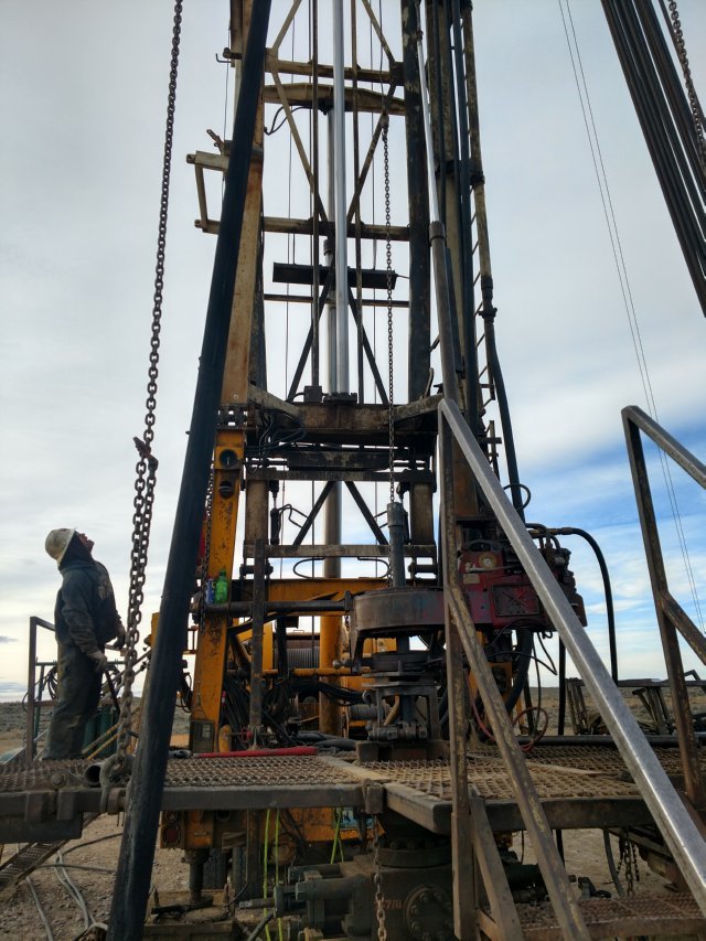
The automatic operation equipment for minor workover is mainly composed of a wellhead operation device, hydraulic elevator, pipe and rod transmission and arrangement device and electro-hydraulic control system.
The device adopts the structural form of dispersing the functional modules and integrated installation on the workover rig: with the hydraulic tong, manipulator and anti splash snap device set on the derrick of the workover rig, which can expand and rotate, and the safety slip is installed above the BOP.
The device only needs to install safety slips, which realizes rapid installation and migration and shortens the auxiliary working time. The device has the function of moving back and forth, left and right, which is convenient to align the wellhead. The height of the hydraulic tong is adjustable and can adapt to the wellhead with different heights. Hoisting equipment and special transport vehicles are not required for the installation and removal of the device.
The main electric control box can be installed on the operation vehicle or integrated into the modular wellhead operation device. The make-up torque of various oil pipes is set on the touch screen to realize automatic make-up and break-down. Equipped with video monitoring, process prompt, safety alarm, etc. The control system has a perfect action interlocking function to ensure the safety and reliability of the workover operation process. All of the electric cabinets, sensors, connectors meet the requirement of Explosion-proof on field.

This website is using a security service to protect itself from online attacks. The action you just performed triggered the security solution. There are several actions that could trigger this block including submitting a certain word or phrase, a SQL command or malformed data.

Position SummaryThe Workover Rig Derrick hand, performs and maintains service on oil wells as part of a 3-5 person crew of a workover rig. Works closely with various field personnel as a team. Maintains and implements all parts of a rig, demonstrating knowledge of all aspects and equipment on site. Essential FunctionsPerforms all well servicing tasks from an elevated position (rod basket or tubing board)Assists in rigging up or downPicks up or laying down tubingWorks the floors or operating the rig when necessaryOperates a Company vehicleComplete time sheets and work tickets accuratelyPerform physical labor which may require heavy lifting (50lbs +),bending, stooping, pushing and pulling, etc.Attend monthly safety meetingsRequirementsHigh school diploma, GED or equivalent1-2 years of Derrickhand experienceBasic oilfield well servicing experienceBasic problem-solving and organizational skillsAbility to perform duties in adverse weather conditionsAbility to effectively communicate, both oral and written - Excellent customer serviceAbility to bend, stoop and lift objects of up to 75 pounds for extended periods of timeAbility to multi-task and work in a fast-paced environmentPreferred Qualifications2+ years Derrick hand experience2+ years related oilfield experienceTo ApplyComplete our employment application and upload your resume to the Careers page of our website at www.contango.com or go directly to our jobs page at http://contango.applicantpro.com/jobs/.
We OfferContango Oil & Gas Company offers competitive salary, cash bonus and stock incentive bonus plans. The Company also offers a comprehensive benefit package which includes medical/dental/vision plans, company paid life and disability insurance, 401(k) retirement plan contribution matching with 100% immediate vesting, paid vacation and sick time, and much more. International ConsiderationsExpatriate assignments will not be considered. Contango Oil & Gas Company regrets that it is unable to sponsor employment Visas for this position. EEO StatementContango Oil & Gas Company is an equal opportunity employer. All qualified applicants will receive consideration for employment without regard to race, color, religion, national origin, sex, gender identity, sexual orientation, age, genetic information, or pregnancy, status as a protected veteran, status as a qualified individual with a disability, or any other status protected by federal, state or local law.If you are a qualified individual with a disability or a disabled veteran, you may request a reasonable accommodation if you are unable or limited in your ability to use or access Contango"s online application as a result of your disability. Please email HR@contango.com or call 405-252-5709 to request reasonable accommodation(s).Job Posted by ApplicantPro

Our Rig 8 is a Service King Manufacturing double drum back in unit The drawworks main drum is grooved for 1” wire rope and the sandline drum is fitted with 9/16” sand line. This unit is powered by Series 60 Detroit Diesel electronically controlled engine with an Allison CLT-750 six speed automatic transmission. The derrick is a SKM 96 ft double, hydraulically raised and scoped with a rating of 220,000 lbs. with 6 lines. This rig comes with a self-contained 14’ wide x 10’ long adjustable working floor. The floor has a working height of up to 14’. It comes complete with stairs and handrails. Complimenting the Rig are Oil Country tubing tongs, Oil Country type “C” air slips, elevators for 2 3/8” and 2 7/8” tubing and 6 joints of 2 3/8” tubing. The above equipment will be supplied with a 4 man crew and a Tool Pusher.

Our Rig 8 is a Service King Manufacturing double drum back in unit The drawworks main drum is grooved for 1” wire rope and the sandline drum is fitted with 9/16” sand line. This unit is powered by Series 60 Detroit Diesel electronically controlled engine with an Allison CLT-750 six speed automatic transmission. The derrick is a SKM 96 ft double, hydraulically raised and scoped with a rating of 220,000 lbs. with 6 lines. This rig comes with a self-contained 14’ wide x 10’ long adjustable working floor. The floor has a working height of up to 14’. It comes complete with stairs and handrails. Complimenting the Rig are Oil Country tubing tongs, Oil Country type “C” air slips, elevators for 2 3/8” and 2 7/8” tubing and 6 joints of 2 3/8” tubing. The above equipment will be supplied with a 4 man crew and a Tool Pusher.
Double/Triple 96" x 225,000# derrick, 60 Series Detroit engine, mounted on 4 axle carrier, 750 Allison transmission, sandline, blocks Price: $72,500
Refurbished, Double/Triple, 96" x 215,000# derrick, Detroit 60 Series, mounted on 4 axle carrier, 750 Allison transmission, sandline, blocks Price: $102,500
Year 2006, double drum, 8V71 Detroit diesel engine, 5860 Allison automatic transmission, mounted on 5 axle Crane Carrier, 108’ x 225,000# derrick, 100 ton McKissick 3-sheave block, fully tooled with 6’ bailers,...
Built 1980, 102" x 260,000# derrick, factory rebuilt Detroit 8V92T engine installed April 2010, inframe on motor 2015 derrick sandblasted and magnafluxed July 2006, new chain on ...
Manufactured 1983, 70" x 120,000# non telescoping stiff mast, double drum 26 x 8, Detroit 6V71 diesel engine, 740 Allison transmission with Spicer power divider, mounted on 4 axle carrier. Rig runs and truck d...
Derrick fell onto rig when being raised, derrick would need to be replaced or repaired. Built 1981, double drum, 42 x 12, 42 x 8, swab drum removed from jack shaft, 5-axle back in carrier, 250,000# derrick wi...

The self-tightening guy wire drilling and workover machines of derrick.A kind of self-tightening guy wire drilling and workover machines, including ship shape under derrick, chassis on chassis, chassis
Base, derrick is divided into the derrick upper body and derrick lower body that mutual sliding is set with, and there is overhead traveling crane upper end, derrick upper body, derrick body has two
Between platform both sides, quadruple board platform guy wire is connected between quadruple board platform and rig floor, and two lower body Radix Saposhnikoviae guy wires are connected on derrick lower body
Between end and wing base, two upper body Radix Saposhnikoviae guy wires are connected between upper end, derrick upper body and wing base, and vehicle frame guy wire is connected to
Technical solution of the present utility model is: self-tightening guy wire drilling and workover machines, including chassis, electromotor, variator, angle
The utility model has the advantages that: 1, self-tightening anchor rope workover rig is that load guy line, wind load guy wire are installed on master by one
Rope is connected between overhead traveling crane and rig floor both sides, and two guy wires of quadruple board platform are connected between quadruple board platform and rig floor, two lower body Radix Saposhnikoviaes
Guy wire is connected between derrick lower body upper end and wing base, and two upper body Radix Saposhnikoviae guy wires are connected to upper end, derrick upper body and wing base
Between, two vehicle frame guy wires are connected between upper end, derrick upper body and vehicle frame fore-stock both sides.) workover rig.During operation prepares
Need not make earth anchor and load guy line, wind load guy wire are installed, substantially increase workover treatment efficiency, reduce operating cost and work
Intensity, decreases well site and installs floor space.2, derrick uses 29 meters of binodal open front п type truss suit stretching structures, design
Y type derrick base, couples all-in-one-piece derrick form with after-poppet, derrick lower body three.Rising and falling by raising cylinder of derrick
Realizing, upper joint derrick is stretched by long fluid cylinder, and upper and lower joint derrick uses gas control automatic lock dog locking technology, equipped with inclination angle on derrick
Indicator, regulates derrick angle by leading screw.Derrick uses multiaxis sky bassinet structure, and wherein overhead traveling crane is to vehicle frame (frame front cross beam two
Side) guy wire, derrick lower body to vehicle frame guy wire, overhead traveling crane to derrick footing (on the wing base of boat shaped base both sides) guy wire, derrick lower body
To derrick footing guy wire, overhead traveling crane to rig floor guy wire and quadruple board platform to rig floor guy wire.In order to prevent workover rig fore-and-aft direction from occurring
Toppling phenomenon, workover rig vehicle frame is connected with boat shaped base by pull bar, and on boat shaped base, the increase in density of channel-section steel is joined to increase
Weight, further reduces complete machine fore-and-aft direction and inclines the probability of boundary.3, the workover rig of self-tightening guy wire formula is ensureing job safety

This disclosure relates to apparatus and methods of stably supporting self-propelled derrick rigs such as workover rigs, drilling rigs, cranes and the like, using a portable base beam.
A completion or workover rig is used to do repair work on a well, such as tubing or pump replacement. When a workover rig is used to do repair work on a well, the rig must be able to pull weights near the rated capacity of the derrick of the rig, withstand high wind gusts, and otherwise be stably supported. Further, a workover rig should operate to its design capacity on a high frequency basis, and be highly mobile and self-contained.
A trend in workover rigs to maintain mobility and higher load capacities has been to use guy wires to stabilize the rig. The use of guys can significantly increase the rated capacity of the rig without changing the basic design.
However, there are drawbacks to a guy system. For example, guy wires need to be in specific locations for the stability and safe operation of the rig, and setup time is longer with a guy setup due to the specific locations. In addition, workover rigs typically tie off to permanent anchors set in the ground in a rectangular pattern around the well head. However, with the growing utilization of multi-well pads, it is nearly impossible to guy the workover rig to the anchors that were originally set in the ground when the well was drilled.
Solutions have been sought to solve the problem of a workover rig not being able to be supported by permanent anchors. One solution has been to utilize one or more base beams that are heavy, portable structures placed on the ground and to which the workover rig is guyed. Existing base beams have a relatively small footprint as well as set locations with which to attach guy wires, which makes set-up easier and faster.
Improvements to base beams and self-propelled derrick rigs are described. A self-propelled derrick rig as used herein is intended to encompass any type of self-propelled vehicle that has a derrick structure mounted on it which can be moved to a raised position during use, a driver"s cab and an engine for propelling the vehicle. Examples of self-propelled derrick rigs include, but are not limited to, workover rigs, drilling rigs, cranes and the like.
When the self-propelled derrick rig is mounted to the base beam, the assembly will be able to withstand high hook loads and wind loading without the danger of the rig coming off of its wheels or falling over. The self-propelled derrick rig can be easily and quickly mounted to the base beam. The assembly also allows support equipment, for example a portable pipe handling machine in the case of a workover rig, to work alongside it. In addition, the base beam can be transported as a single load on a vehicle, for example on a flatbed truck.
The base beam includes stabilizer arms that are attached, for example pivotally attached, to the base beam to help stabilize the base beam and the rig itself. A height adjustable stabilizer pad can be connected to each stabilizer arm to help level the stabilizer arms and the base beam on the ground.
In addition, to the base beam, a unique counterweight assembly is described that in use is connected to the front of the rig to help stabilize the rig and prevent the front of the rig from coming off of the ground.
In one embodiment, a base beam that is used to support a self-propelled derrick rig includes a longitudinally extending metal main beam having first and second opposite ends, a front side, a back side, a top and a bottom, where the bottom is substantially planar. The main beam includes a central section approximately midway between the first and second ends thereof on which the derrick structure of the rig will be supported. The central section can reinforced between the top and the bottom, and the top of the central section is substantially planar. First and second stabilizer arms are attached, for example pivotally attached or non-pivotally attached, to the main beam when pivotally attached, the stabilizer arms are pivotable relative to the main beam between a refracted or transport position where the first and second stabilizer arms are generally parallel to the main beam and a fully extended or deployed position where the first and second stabilizer arms are not parallel to the main beam. In addition, at least one guy attachment point is provided on each of the first and second stabilizer arms to allow guys to attach between the derrick structure and the stabilizer arms.
In still another embodiment, an assembly is provided that includes a base beam and a self-propelled derrick rig. The base beam can include a longitudinally extending metal main beam having first and second opposite ends, a front side, a back side, a top and a bottom, and a central section. First and second stabilizer arms can be attached, for example pivotally attached or non-pivotally attached, to the main beam. When pivotally attached, the stabilizer arms are pivotable relative to the main beam between a retracted position where the first and second stabilizer arms are generally parallel to the main beam and a fully extended position where the first and second stabilizer arms are not parallel to the main beam. The self-propelled derrick rig can include a derrick structure adjacent a first end of the rig that is disposed in a raised position, a driver"s cab, and an engine that provides power for propelling the rig. A base of the derrick structure can be supported on the central section of the main beam on the top thereof. In addition, a plurality of guys extend between the derrick structure and the rig, and a plurality of guys extend between the derrick structure and the base beam.
In yet another embodiment, the counterweight assembly includes a sled that has a mechanism to connect the sled to the self-propelled derrick rig. The connection can be the sled simply resting on the front of the rig to weigh down the front end, or the sled can be removably attached to the rig. A plurality of weights are removably disposed on the sled. Each weight is individually separable from the other weights and each weight is individually removable from the sled.
In another embodiment, a method of supporting a derrick structure of a self-propelled derrick rig is provided, where the derrick structure is disposed adjacent to a first end of the rig and is movable between a raised position and a lowered position. In the method, a base beam is arranged on the ground, and stabilizer arms that are pivotally or non-pivotally connected to the base beam are deployed from a retracted position to a fully deployed position. The self-propelled derrick rig is arranged adjacent to the base beam, and the derrick structure of the self-propelled derrick rig is raised to the raised position. A base end of the derrick structure is attached to the base beam. In addition, a plurality of guys are attached between the derrick structure and the remainder of the rig and a plurality of guys are attached between the derrick structure and the base beam.
In another embodiment of a method, a base beam is arranged on the ground, and the self-propelled derrick rig is arranged adjacent to the base beam. The derrick structure of the self-propelled derrick rig is raised to the raised position, and a base end of the derrick structure is attached to the base beam. A plurality of guys are attached between the derrick structure and the remainder of the rig and a plurality of guys are attached between the derrick structure and the base beam. A counterweight assembly is also connected to the rig at a second end thereof opposite the first end and the derrick structure to weigh down the front of the rig.
As described in further detail below, an improved base beam is described that is used to support a self-propelled derrick rig. A self-propelled derrick rig as used herein is intended to encompass any type of self-propelled vehicle that has a derrick structure mounted on it which can be moved to a raised position during use, a driver"s cab and an engine for propelling the vehicle. Examples of self-propelled derrick rigs include, but are not limited to, workover rigs, drilling rigs, cranes and the like. The self-propelled derrick rig will be described below as, and is illustrated in the drawings as, a workover rig. However, the derrick rig can be any other type of rig that can benefit from being supported using a base beam(s) as described herein.
With reference initially to FIG. 1, an assembly 10 is illustrated that includes a base beam 12 that is shown together with a self-propelled derrick rig 14 in the form of a workover rig. The base beam 12 is disposed adjacent to a well head 16, with the rig 14 being used to perform a service function on the well.
The rig 14 includes a derrick structure 18 disposed adjacent to a first or rear end of the rig, where the derrick structure includes a raised position (shown in FIG. 1) and a lowered position (shown in FIG. 4). The rig 14 also includes a platform 20, a driver"s cab 22 disposed on the platform adjacent to a second or front end of the rig, wheels 24 mounted on the platform 20, and an engine 26 adjacent to the front of the rig that provides power for propelling the rig during driving of the rig.
In the raised position of the derrick structure 18 shown in FIG. 1, a base of the derrick structure 18 is supported on the base beam 12. In addition, a plurality of guys 28 extend between the derrick structure 18 and different points on the remainder of the rig 14, and a plurality of guys 30 extend between the derrick structure 18 and the base beam 12.
The main beam 40 further includes a substantially planar central section 50 approximately midway between the first and second ends 42 a, 42 bthereof. As discussed further below with respect to FIGS. 4-5, in use the central section 50 supports the base of the derrick structure 18. Therefore, if considered necessary to support the derrick structure, the central section 50 of the main beam can be reinforced between the top 48 and the bottom, for example by employing internal reinforcing members disposed within the main beam 40 at the central section 50.
In the illustrated embodiment, when fully deployed, the swing arms 52 a, 52 bextend from the front side 44 of the main beam and are disposed at generally right angles to the longitudinal axis A-A. As shown in FIG. 2, each of the first and second swing arms has a length L, and the combined length of the first and second swing arms 52 a, 52 bcan be less than the longitudinal length of the main beam to permit the swing arms to completely fold to the retracted position parallel to the axis A-A. However, as discussed further below, other configurations of the swing arms are possible.
The base beam 12 further includes a plurality of guy attachment points to permit attachment to the guys 30. The guy attachment points can be provided at locations that one determines to be suitable for adequately guying the derrick structure 18. In the embodiment illustrated in FIGS. 2 and 3, there is at least one guy attachment point 60 on each of the first and second swing arms, for example adjacent to the second ends 56. In addition, there can be a plurality of guy attachment points 62 on the main beam 40, for example adjacent to the ends 42 a, 42 b. The guy attachment points 60, 62 can be, for example, flanges that are attached to the base beam 12 and that include a hole to permit attachment of one end of the guys. The guys 30 (as well as the guys 28) can be wires or any structure suitable for use as guys.
Other configurations of the base beam are possible. For example, FIG. 10 illustrates a base beam 212 with a main beam 240 and a pair of swing arms 252 a, 252 bpivotally attached to the main beam 240 for pivoting movement between a retracted position (not shown) where the first and second swing arms are generally parallel to the main beam and a fully extended or deployed position (shown in FIG. 10) where the first and second swing arms are not parallel to the main beam. In this embodiment, the swing arms are pivotally attached to the main beam 240 so that the first and second arms 252 a, 252 bextend from a back side of the main beam when in the fully extended position in a direction generally toward the front end of the rig 14 and parallel to the rig.
FIG. 14 illustrate a base beam 512 with a main beam 540 and a pair of swing arms 552 a, 552 bpivotally attached to the main beam 540 for pivoting movement between a retracted position (not shown) where the swing arms are generally parallel to the main beam and a fully extended or deployed position (shown in FIG. 14) where the swing arms are not parallel to the main beam. In this embodiment, the swing arms 552 a, 552 bare pivotally attached to the main beam 540 away from the ends of the beam 540 and more toward the center of the main beam. In addition, the swing arms do not extend at right angles to the main beam as in the other embodiments. Instead, the swing arms 552 a, 552 bare disposed at acute angles α relative to the longitudinal axis of the main beam.
Returning now to FIGS. 1-3 together with FIGS. 4-5, in use, the base beam is transported to a position adjacent to the well head 16 and arranged on the ground. The swing arms are then deployed from the retracted position, which is used during transport of the base beam, to the fully deployed position. If necessary, the stabilizer pads 58 are adjusted in height to level the swing arms and the main beam. The self-propelled derrick rig 14 is then backed up to a position adjacent to the base beam as shown in FIG. 4. During this time, the derrick structure 18 is likely at its lowered or transport position as shown in FIG. 4, although in some circumstances the derrick structure could already be raised or partially raised. If the derrick structure is not raised, the derrick structure is raised to the raised position shown in FIG. 1.
With reference to FIG. 5, once the derrick structure 18 is raised, a base end 70 of the derrick structure is attached to the base beam 12. In particular, one side of the base end 70 is pivotally connected to the rig platform 20 by pivots 72. The other side of the base end is provided with a pair of height adjustable stabilizer pads 74. Metal plates 76 are laid on the top 48 of the main beam at the central section 50, and the pads 74 rest on the plates 74. The base end 70 is fixed to the main beam by one or more fixation members 78. In one embodiment, four fixation members 78 can be used, each of which attaches at one end to the base end 70 of the derrick structure 18 and attach at opposite ends thereof to mounting fixtures 80 that are disposed adjacent to the front side and the back side respectively of the main beam adjacent to, and on opposite sides of, the central section 50. In the illustrated embodiment, the fixation members 78 comprise shackles, although any type of fixation members that can adequately attach the base end of the derrick structure to the main beam can be used.
In addition, as shown in FIG. 1, the guys 28 are then attached between the derrick structure and the remainder of the rig, and the guys 30 are attached between the derrick structure and the base beam. FIG. 1 illustrates the derrick structure 18 as including a rig floor 82 and a tubing or racking board 84 both of which are conventional structures on workover rigs. The guys 28 are illustrated as generally extending from the top of the derrick structure to other points on the rig. Some of the guys 30 extend from the base beam to the top of the derrick structure, while some of the guys 30 extend from the base beam to the tubing board 84 and from the tubing board to the top of the derrick structure. However, the exact arrangement and number of the guys 28, 30 can vary based on a number of factors, such as the expected loading conditions on the derrick structure and the rig. Therefore, the guy arrangement illustrated in FIG. 1 is exemplary only and can vary from the illustrated arrangement both in the number of guys 28, 30 used and their locations.
Under some loading conditions, for example when the derrick structure is pulling at or near capacity, the front end of the rig 14 may want to come off the ground. To prevent such an occurrence, an optional counterweight assembly 90 can be used that is connected to the front end of the rig 14 to weigh down the front of the rig. The assembly 90 can simply connect to the front of the rig by resting on some portion of the front. Alternatively, the assembly 90 can be connected to the rig by removably attaching the assembly to the rig, for example by pinning or bolting the assembly to the rig. Any form of connection can be used as long as the assembly 90 increases the weight of the front of the rig.
With reference to FIGS. 6-8, the counterweight assembly 90 can include a sled 92 that is designed to connect to the rig 14 and carry separate weights 94 that can be added and removed from the sled 92 to alter the amount of weight carried by the sled.
The sled 92 is a generally rectangular structure that includes a base 96, reinforcing members 98 at each side end of the base, a front side 100 and a rear side 102. The rear side 102 of the sled 92 includes a plurality of vertical beams 104 connected at base ends thereof to the base 96 and at upper ends thereof to a horizontal beam 106. As best seen in FIG. 8, the horizontal beam 106 and/or the beams 104 can be connected to a block, for example of wood, that rests on a ledge at the front of the rig. Thus, the assembly 90 weights down the front end of the rig.
If there is concern that the assembly could move, the assembly could be removably attached to the rig. For example, with reference to FIG. 16, the attachment mechanism can comprise flanges 116 that are fixed to the beam 106 and/or the beams 104, with corresponding flanges 118 on the front of the rig that align with the flanges on the sled. Pins or bolts 119 can then extend through holes in the aligned flanges to attach the sled to the rig.
The sled 92 further includes at least one guy attachment point 114. For example, in the illustrated embodiment, the sled includes a plurality of the guy attachment points 114, with the guy attachment points being located at the rear side 102 of the sled. As best seen in FIGS. 1 and 8, two guys 28 extend from the derrick structure 18 to the attachment points 114 to guy the counterweight assembly to the derrick structure.
With reference to FIG. 13, an embodiment is illustrated that uses two base beams. One base beam 120 is substantially similar to the base beam 12. Alternatively, the base beam 120 could be similar to the base beams 212, 312, 412, or 512. A second base beam 122 is disposed underneath the rig 14, for example underneath jacks or outriggers that are provided on the rig 14. The construction and use of jacks or outriggers on rigs is well known in the art. In this embodiment, guys 124 extend from the derrick structure 18 and are connected to the ends of the second base beam 122 to help support the derrick structure.
FIG. 15 shows another embodiment that uses two base beams, including one base beam 130 that is substantially similar to the base beam 12. In this embodiment, a second base beam 132 is disposed underneath the rig 14 at a location that is further forward than the second base beam 122 in FIG. 13. For example, the second base beam 132 can be disposed underneath jacks disposed under the driver"s cab 22, and guys 134 extend from the derrick structure 18 and are connected to the ends of the base beam 132 to help support the derrick structure.
Steel Fabrication, Machining, Welding, Coatings, Snubbing Units, Workover Rigs, Rotary Tables, Power Packs, Casing Jacks, Hydraulics, Pump Motor Skid, Oilfield Tools & Equipment

In 1983, Ernie began his apprenticeship at the Iron Workers Local 84. Attending night classes and earning my diploma with training in blue print reading, welding, fabricating, rigging, and rod tying. During the day, he received on the job training by working on erecting several buildings in the Houston area, continuing this line of work for about ten years. In 1993, while continuing to work for the Local 84 union, he moved into “Rigging” with Sullivan Transfer. They moved (Rigged) heavy machinery and large vessels located in refineries all over the United States. We were well known as the “Specialty Riggers” in several States.
Ernie began his Rig Building career working in the Oil and Gas Industry for Dreco Manufacturers in 1996, then working for National Oilwell Varco (NOV) in 1997. For the next six years, Ernie honed his skills, working as a Rig Builder, building/erecting oil derricks, installing equipment, rebuilding crowns, and special rigging jobs all over the world while working as a Supervisor during that time. In 2003, he became the Structural Supervisor with over 25 workers reporting to him, and was in charge of staffing and equipment, erecting Derricks and installing equipment located all over the world. Working for several well-known companies in the Oil & Gas Industry.
In 2005, he became Manager of the “Structural Group” at NOV, with up to 45 employees reporting to him. They worked closely with customers, which had very important deadlines to meet with day rates exceeding 500 thousand dollars per day. On several occasions, they were called upon to get the clients back in service, in the shortest amount of time, these jobs were known as “Rig Downs.”
In 2012, Ernie began working for Polar Rig Specialties as a Sr. Operations Manager, assisting to man crews for Rig Building jobs globally, and also welding / fabricating / Rigging / Crown repair. In 2014, he began working for Rig Recourses, Derrick Project specialist out of Singapore pushing crews globally, with welding / fabricating / Rigging / Crown Repair / Rope Access.
By 2017, he returned to Polar Rig as Vice President, assisting customers with different projects globally. Some of the work scopes we assist with are the following: Welding, fabricating, rigging, Crown repairs, Top Drive / Traveling Block change out, rope access, and more. Polar Rig has clients all over the world and has assisted in Derrick Building & Equipment Installation in the Oil and Gas Industry for many years. Polar Rig also assists customers with “Rig Downs” situations, getting the oil derrick up and running in the shortest amount of time. Polar Rig and their employees have been called the best in the business.

In March of 2021, Archer Limited (Archer) again awarded Derrick and their distributor, Rotor Offshore, a shale shaker upgrade for an Equinor platform rig. This contract is four Dual Pool® 626 Vapor Extraction (VE) shale shakers for Equinor’s Visund platform located in the Tampen area of the Norwegian North Sea. Due to spacing constrictions on the rig, the shakers required customization and Derrick’s engineering team was able to adapt their standard design for the project. This is the seventh shaker upgrade with Dual Pool 626 shaker on Equinor platform rigs. It also marks the third offshore rig upgrade in Norway that our Distributor partner, Rotor Offshore, has won since joining the Derrick team in 2019. Delivery is scheduled for September 2021 following a witnessed FAT.
Previous contract awards for Dual Pool 626 shakers include Norway platform rigs Statfjord A, B, and C; Grane; and Njord A as well as Peregrino A located offshore Brazil.
Rotor Offshore is centrally located at Lysaker (Oslo) and Sola (Stavanger) in Norway and has, since May 2019, been the exclusive representative for Derrick Corporation (US) for the Norwegian Oil and Gas Market.
Derrick, founded in 1951, is a family-owned and operated company with a global presence focused on pioneering fine-separation technology. Since 1977, Derrick has manufactured innovative technologies for the Oil & Gas Drilling Industry. Derrick offers its clients leading-edge solutions and around-the-clock, award- winning service to maximize solids control efficiency. Derrick’s products are renowned for their rugged reliability in an industry known for its intensely challenging environment and ever-evolving demands.


 8613371530291