
workover rig elevators free sample

Considering the number of Workover Rigs off contract and stacked it is now highly important that contractors have their equipment in ready to go on contract condition. Major oil companies and operating companies will require a history of good Rig Maintenance.
This Workover Rig Maintenance program consist of a complete maintenance schedule for all the equipment listed below. Any item listed on any of the check list worksheets can be changed and edited to suite any Workover Rig and any piece of equipment. It also covers Diesel Haulers and Water Haulers if you own your own trucks. Any item can be removed or changed to suite your Workover Rig and equipment.
A hole in the rig floor 30 to 35 feet deep, lined with casing that projects above the floor. The kelly is placed in the rathole when hoisting operations are in progress.†
The top drive rotates the drill string end bit without the use of a kelly and rotary table. The top drive is operated from a control console on the rig floor.†
The global elevator and escalator market size is estimated at around USD 79.9 billion in 2021. This huge figure is expected to increase at a compound annual growth rate (CAGR) of 6.4% up till 2028. With such promising current market size and market growth rates, it can be a good idea for businesses to enter the industry. One way to capitalise on this market is by buying wholesale elevator links for drilling rig and reselling them to installation and repair service businesses, malls and landlords. You can also use them directly as part of your own business.
When buying or selling wholesale elevator links for drilling rig, it is important to understand the different types of elevators there are. Hydraulic elevator components are different from traction elevator components. Hydraulic elevator components include a tank, motor pump, valve, and actuator. Meanwhile, a standard traction elevator will have a motor, drive sheave, brake and machine bed plate.
Understanding the type of elevator links for drilling rig your customers use or are looking for can help you to recommend the correct elevator links for drilling rig for them. Sometimes, even if all the elevator door parts and other elevator links for drilling rig are perfectly fine, it may be good for your customers to have elevator spare parts in case of emergency.

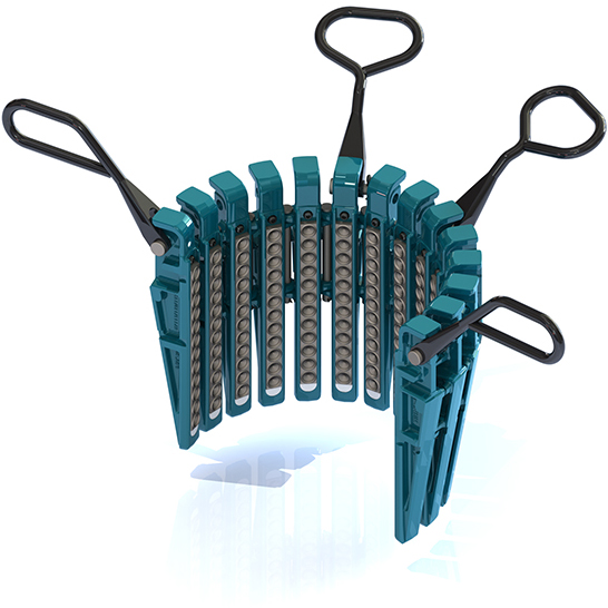
This invention relates generally to elevator systems that are utilized on well drilling rigs for hoisting and lowering various types of pipe such as drill stem, well casing and well tubing. More specifically, the present invention concerns the provision of a drilling rig elevator assembly having replaceable pipe support inserts that enable a single elevator frame assembly to be selectively adapted for hoisting various types and sizes of pipe during well drilling and completion activities.
In the drilling industry, it is the usual practice to hoist various types of pipe such as drill stem, well casing and well production tubing with various elevators of different capacities. The internal diameters and configurations of the elevators are specifically dressed for precise interfitting relation with the tool joints of the pipes to be handled. Under normal well drilling and completion operations, it is therefore necessary to maintain readily available to the working floor of the drilling rig a wide selection of elevators with different capacities and diameters so that the various types and sizes of pipe and casing may be handled as needed during various phases of the well drilling and completion operations.
As drilling rig elevators are designed for carrying substantial loads, the operating personnel of a drilling rig must carefully select specific elevators that are intended for a particular function or purpose. A wide selection of elevators must therefore typically be maintained in the immediate vicinity of the working floor of the drilling rig and must be periodically changed out in order to provide for the handling the different types and sizes of pipe that are to be used. Obviously, the need for changing out elevators each time there is a change in the type of pipe or casing to be handled becomes a significant expense that detracts from the commercial viability of the drilling operations from the standpoint of both equipment cost and lost productivity. For lowering or hoisting pipe of different sizes, elevators must be exchanged i.e., actual drilling time is reduced by this elevator exchange operation. Accordingly, it is desirable to provide a novel drilling rig elevator assembly having the capability for simple and efficient low cost conversion thereof to permit its selective handling of the various types and sizes of pipe, casing and tubing that are to be handled during well drilling and completion operations.
It is therefore a principal feature of the present invention to provide a novel drilling rig elevator system that may be readily adapted without replacement so that it will receive and efficiently handle all of the types and sizes of pipe and casing that are hoisted and lowered during well drilling and completion operations.
It is another feature of this invention to provide a novel elevator system for drilling rigs wherein a single elevator frame may be employed and wherein elevator inserts may be selectively utilized to adapt the elevator frame for hoisting and lowering any particular size or type of pipe that is to be handled.
It is an even further feature of the present invention to provide a novel elevator system for well drilling operations wherein a moveably joined elevator frame assembly is provided which defines frame sections having internal insert receptacles and wherein various types of pipe clamping inserts are selectively disposed in interlocking and yet easily removable assembly with the respective elevator frame sections to permit simple and efficient replacement of elevator inserts without involving significant capital equipment expense, manual labor costs or drilling rig downtime.
FIG. 1 is a plan view of a drilling rig elevator assembly having a pair of frame sections that are shown pivoted to the open condition thereof and further showing a clamping insert being rotatably moved as shown by a motion arrow for rotatably sliding it into interlocking assembly with its frame section.
FIG. 2 is an elevational view of the drilling rig elevator assembly of FIG. 1 showing the elevator assembly in its closed and latched condition and with both clamping inserts fully assembled and locked immovably with respect to individual elevator frame sections.
FIG. 4 is an exploded fragmentary sectional view of the upper portion of the drilling rig elevator and clamping insert assembly of FIG. 3 for illustrating the manner by which the clamping inserts are secured in immovable relation with respective frame sections.
FIG. 5 is a fragmentary sectional view of a lower portion of the drilling rig elevator and replaceable insert assembly of FIG. 3 and showing an example of the interlocking relationship that is established between the elevator frames and clamping inserts.
FIG. 6 is an elevational view of a drilling rig elevator assembly constructed in accordance with the present invention and having a central portion thereof broken away and shown in section for illustration of an alternative embodiment for interlocking connection of clamping inserts therein, the clamping inserts having a particular internal profile and dimension for hoisting and lowering pipe of a particular type and dimension.
FIG. 7 is a fragmentary sectional view of the drilling rig elevator assembly of FIG. 6 showing an interlocking receptacle and interlocking flange being disposed in interengaging relation.
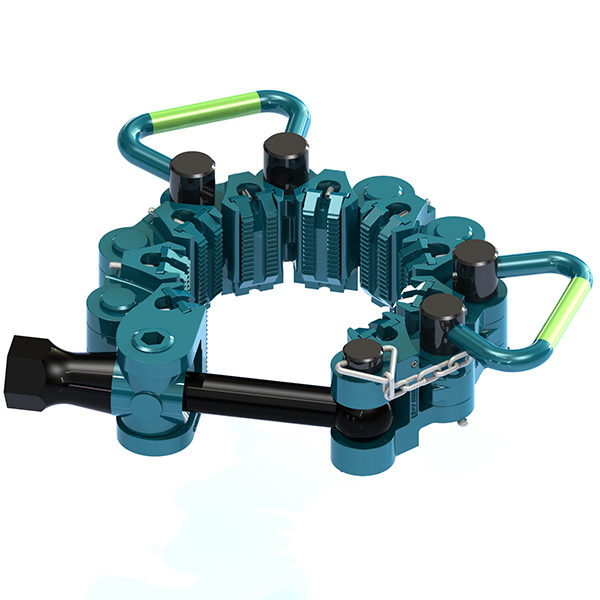
Referring now the drawings and first to FIGS. 1-3, an elevator mechanism for use on drilling rigs for hoisting and lowering various types and sizes of pipe is shown generally at 10 and incorporates a pair of elevator frame sections 12 and 14 that are movably interconnected by means of a pivot assembly 16. As is more evident from FIG. 3, each of the frame sections defines support means that enable the elevator to be supported by the elevator links of a conventional drilling rig hoist mechanism. As shown in FIG. 3, the elevator frame section 12 defines upper and lower vertically spaced arms 18 and 20 that define respective connection flanges 22 and 24. These flanges define apertures 26 and 28 respectively, that receive bolts or other suitable connector elements which secure the upper and lower ends of an elevator retainer element to the frame section in a manner closing the elevator link opening 30 that is defined by the spaced arms 18 and 20. The opposite elevator frame section 14 is also provided with support arms 32 and 34 defining a space 36 therebetween and providing retainer connector flanges 38 and 40 which receive another elevator link retainer, not shown. With the elevator link retainers removed, the lower loops of a pair of elevator links are positioned within the respective openings or receptacles 30 and 36 with portions of the support loops surrounding the respective upper arms 18 and 32 of the elevator frame sections. After this has been done, the elevator link retainers are then assembled to the respective retainer flanges and are secured by bolts or pins or any other suitable connectors to close the outer portions of the openings and secure the elevator links in movably connected and supporting relation with respective elevator frame sections. Although a center latch type elevator mechanism is shown in FIGS. 1-3, it should be understood that this embodiment is only intended to identify the scope of this invention. Other types of elevator mechanisms, such as side door elevators for example, may also be manufactured in accordance with the spirit and scope of the present invention.
In the case of manually operated elevator mechanisms such as shown in FIGS. 1-3, the elevator frames 12 and 14 may be provided with respective actuator arms 42 and 44, each having actuator handles 46 and 48, respectively. The frame sections are also provided with an appropriate latch mechanism so that, when pivoted to the closed position for clamping about pipe to be hoisted or lowered, the elevator mechanism will remain latched until such time as it is controllably unlatched and opened. As shown particularly in FIGS. 1 and 2, elevator frame section 12 is provided with a latch element 50 which is movably connected by a pivot 52 to the actuating arm 42 of the frame section. The latch element 50 is provided with a movable latch and latch release element 54 that is pivotally connected thereto by means of a pivot 56. The opposite frame section 14 is also provided with a latch element 58 which, when the elevator frames are closed about a pipe, will be received in interengaging locked relation with respect to latch 50, to thereby secure the elevator frames in the closed position about the pipe. When it is desired to release the pipe, the latch mechanism may be manually actuated to unlatch, after which the actuator arms 42 and 44 may be pivoted apart thereby moving the frames about the pivot 16 from the closed position shown in FIG. 2 to the open position shown in FIG. 1. The basic elevator frame structure described above is of conventional nature. As is typically the case, each of the elevator frame sections will be dressed to receive pipe of a particular size and geometry. Thus, if pipe of a different size or geometry is to be hoisted and lowered by the elevator mechanism, the elevator links must be disconnected from the elevator assembly and another elevator assembly must be interchanged with it so as to adapt the hoisting system of the drilling rig for suitably hoisting and lowering that particular type of pipe. Thus, if the drilling rig is intended to hoist and lower 2, 3 or 4 different types of pipe, for example, drill pipe, well casing, well tubing, etc., then 2, 3 or 4 different types of elevators must be readily available at all times so that they may be changed out and used as needed. When a pipe change is necessary, the drilling rig will experience downtime of the hoisting apparatus sufficiently to disconnect the elevator links from the elevator mechanism being used and reconnect them to another elevator. Thus, elevator downtime adds significantly to the overall costs of the drilling operation. Further, the need for maintaining several elevator assemblies immediately available to the drilling rig floor results in a considerable capital expense which adversely effects the cost of the drilling operation. Therefore, it is desirable to provide a pipe hoisting elevator mechanism that may be simply and efficiently converted from one type of pipe to another to thereby minimize capital expense of the drilling equipment and to also minimize drilling rig downtime that ordinarily occurs during elevator interchange.
According to the principles of the present invention, the various objects and features identified hereinabove are realized through the provision of an elevator mechanism for drilling rigs that is adapted for receiving various types of elevator inserts that quickly and efficiently adapt an elevator assembly for hoisting and lowering a particular type or size of pipe. As shown in FIGS. 1-3, the elevator frame sections 12 and 14 are each provided with essentially semi-circular or arcuate insert receptacles shown generally at 60 and 62. These receptacles are adapted to receive generally arcuate insert segments 64 and 66 which are each appropriately internally dressed for establishing precise interfitting relation with the geometric configuration of the type and size of pipe to be hoisted and lowered.
Typically, the force that is applied to the inserts by pipe is a downwardly directed force which is resisted by the internal shoulder 120 of the insert receptacle which provides support for the external tapered shoulder 154 of the inserts. In the event an upwardly directed force is applied to the insert segments, the lower peripheral flange or shoulder 142 and 144 of the insert segments will secure the insert segments against upward movement. Obviously, in the case of drilling rig hoist apparatus, the downwardly directed force that must be accommodated by the elevator system will significantly exceed any upwardly directed force that it will experience.
A further alternative embodiment of the present invention is shown generally at 160 which is in the form of a side door type drilling rig elevator having a single frame section 162 defining elevator link support arms 164 and 166 and lower elevator retainer arms 168 and 170 that are disposed in spaced relation with the respective elevator support arms and define elevator link receptacles 172 and 174. These receptacles are closed by appropriate retaining elements that are secured thereto by pins or bolts that extend through the respective apertures thereof in the manner described above. The elevator frame 162 will be provided with a pivotally mounted side door type elevator door segment which provides closure for the elevator about a pipe section when the elevator door segment is closed and latched. The elevator frame 162 further defines an internal insert receptacle 176 which is adapted to receive a pipe support insert 178 in mechanically interengaged and locked relation therein. The upper portion of the frame segment 162 defines an upwardly projecting arcuate retainer rim 180 which is of essentially the same configuration and purpose as is discussed above at 124-126 in FIG. 6, for receiving the upper externally flanged end 182 of the insert segment. The undercut receptacle 184 that receives the retainer rim is of corresponding arcuate configuration so as to permit interlocking engagement of the upper portion of the frame and insert by moving the arcuate insert in rotary fashion as is shown by the movement arrow in FIG. 1 until the insert segment has been received in fully engaged and properly positioned relation with its frame section. Also for interlocking interengagement of the lower portion of the insert within the insert receptacle of the elevator frame, the elevator frame is internally machined to define a semi-dovetail groove 186 of arcuate configuration and having an upper upwardly and outwardly inclined frusto-conical surface 188 which defines a downwardly facing support shoulder. Correspondingly, the lower end of the pipe support insert segment 178 is provided with an external locking flange 190 having an upwardly facing frusto-conical surface 192 which prevents upward movement of the insert segment relative of the internal insert receptacle of the elevator frame section. For supporting the insert segment within its receptacle when significant downward load is applied thereto, the frame section defines an internally projecting bottom flange 194 of significant structural integrity which defines an upwardly facing internal shoulder 196 which is disposed for supporting engagement with the downwardly facing lower end 198 of the insert segment. The large circular surface dimension of the shoulder surface 196 provides for even distribution of load from the pipe support insert to the elevator frame. The bottom flange also defines a cylindrical surface 200 defining the central pipe transit opening of the elevator frame.
This invention relates generally to elevator systems that are utilized on well drilling rigs for hoisting and lowering various types of pipe such as drill stem, well casing and well tubing. More specifically, the present invention concerns the provision of a drilling rig elevator assembly having replaceable pipe support inserts that enable a single elevator frame assembly to be selectively adapted for hoisting various types and sizes of pipe during well drilling and completion activities.
In the drilling industry, it is the usual practice to hoist various types of pipe such as drill stem, well casing and well production tubing with various elevators of different capacities. The internal diameters and configurations of the elevators are specifically dressed for precise interfitting relation with the tool joints of the pipes to be handled. Under normal well drilling and completion operations, it is therefore necessary to maintain readily available to the working floor of the drilling rig a wide selection of elevators with different capacities and diameters so that the various types and sizes of pipe and casing may be handled as needed during various phases of the well drilling and completion operations.
As drilling rig elevators are designed for carrying substantial loads, the operating personnel of a drilling rig must carefully select specific elevators that are intended for a particular function or purpose. A wide selection of elevators must therefore typically be maintained in the immediate vicinity of the working floor of the drilling rig and must be periodically changed out in order to provide for the handling the different types and sizes of pipe that are to be used. Obviously, the need for changing out elevators each time there is a change in the type of pipe or casing to be handled becomes a significant expense that detracts from the commercial viability of the drilling operations from the standpoint of both equipment cost and lost productivity. For lowering or hoisting pipe of different sizes, elevators must be exchanged i.e., actual drilling time is reduced by this elevator exchange operation. Accordingly, it is desirable to provide a novel drilling rig elevator assembly having the capability for simple and efficient low cost conversion thereof to permit its selective handling of the various types and sizes of pipe, casing and tubing that are to be handled during well drilling and completion operations.
It is therefore a principal feature of the present invention to provide a novel drilling rig elevator system that may be readily adapted without replacement so that it will receive and efficiently handle all of the types and sizes of pipe and casing that are hoisted and lowered during well drilling and completion operations.
It is another feature of this invention to provide a novel elevator system for drilling rigs wherein a single elevator frame may be employed and wherein elevator inserts may be selectively utilized to adapt the elevator frame for hoisting and lowering any particular size or type of pipe that is to be handled.
It is an even further feature of the present invention to provide a novel elevator system for well drilling operations wherein a moveably joined elevator frame assembly is provided which defines frame sections having internal insert receptacles and wherein various types of pipe clamping inserts are selectively disposed in interlocking and yet easily removable assembly with the respective elevator frame sections to permit simple and efficient replacement of elevator inserts without involving significant capital equipment expense, manual labor costs or drilling rig downtime.
FIG. 1 is a plan view of a drilling rig elevator assembly having a pair of frame sections that are shown pivoted to the open condition thereof and further showing a clamping insert being rotatably moved as shown by a motion arrow for rotatably sliding it into interlocking assembly with its frame section.
FIG. 2 is an elevational view of the drilling rig elevator assembly of FIG. 1 showing the elevator assembly in its closed and latched condition and with both clamping inserts fully assembled and locked immovably with respect to individual elevator frame sections.
FIG. 4 is an exploded fragmentary sectional view of the upper portion of the drilling rig elevator and clamping insert assembly of FIG. 3 for illustrating the manner by which the clamping inserts are secured in immovable relation with respective frame sections.
FIG. 5 is a fragmentary sectional view of a lower portion of the drilling rig elevator and replaceable insert assembly of FIG. 3 and showing an example of the interlocking relationship that is established between the elevator frames and clamping inserts.
FIG. 6 is an elevational view of a drilling rig elevator assembly constructed in accordance with the present invention and having a central portion thereof broken away and shown in section for illustration of an alternative embodiment for interlocking connection of clamping inserts therein, the clamping inserts having a particular internal profile and dimension for hoisting and lowering pipe of a particular type and dimension.
FIG. 7 is a fragmentary sectional view of the drilling rig elevator assembly of FIG. 6 showing an interlocking receptacle and interlocking flange being disposed in interengaging relation.
Referring now the drawings and first to FIGS. 1-3, an elevator mechanism for use on drilling rigs for hoisting and lowering various types and sizes of pipe is shown generally at 10 and incorporates a pair of elevator frame sections 12 and 14 that are movably interconnected by means of a pivot assembly 16. As is more evident from FIG. 3, each of the frame sections defines support means that enable the elevator to be supported by the elevator links of a conventional drilling rig hoist mechanism. As shown in FIG. 3, the elevator frame section 12 defines upper and lower vertically spaced arms 18 and 20 that define respective connection flanges 22 and 24. These flanges define apertures 26 and 28 respectively, that receive bolts or other suitable connector elements which secure the upper and lower ends of an elevator retainer element to the frame section in a manner closing the elevator link opening 30 that is defined by the spaced arms 18 and 20. The opposite elevator frame section 14 is also provided with support arms 32 and 34 defining a space 36 therebetween and providing retainer connector flanges 38 and 40 which receive another elevator link retainer, not shown. With the elevator link retainers removed, the lower loops of a pair of elevator links are positioned within the respective openings or receptacles 30 and 36 with portions of the support loops surrounding the respective upper arms 18 and 32 of the elevator frame sections. After this has been done, the elevator link retainers are then assembled to the respective retainer flanges and are secured by bolts or pins or any other suitable connectors to close the outer portions of the openings and secure the elevator links in movably connected and supporting relation with respective elevator frame sections. Although a center latch type elevator mechanism is shown in FIGS. 1-3, it should be understood that this embodiment is only intended to identify the scope of this invention. Other types of elevator mechanisms, such as side door elevators for example, may also be manufactured in accordance with the spirit and scope of the present invention.
In the case of manually operated elevator mechanisms such as shown in FIGS. 1-3, the elevator frames 12 and 14 may be provided with respective actuator arms 42 and 44, each having actuator handles 46 and 48, respectively. The frame sections are also provided with an appropriate latch mechanism so that, when pivoted to the closed position for clamping about pipe to be hoisted or lowered, the elevator mechanism will remain latched until such time as it is controllably unlatched and opened. As shown particularly in FIGS. 1 and 2, elevator frame section 12 is provided with a latch element 50 which is movably connected by a pivot 52 to the actuating arm 42 of the frame section. The latch element 50 is provided with a movable latch and latch release element 54 that is pivotally connected thereto by means of a pivot 56. The opposite frame section 14 is also provided with a latch element 58 which, when the elevator frames are closed about a pipe, will be received in interengaging locked relation with respect to latch 50, to thereby secure the elevator frames in the closed position about the pipe. When it is desired to release the pipe, the latch mechanism may be manually actuated to unlatch, after which the actuator arms 42 and 44 may be pivoted apart thereby moving the frames about the pivot 16 from the closed position shown in FIG. 2 to the open position shown in FIG. 1. The basic elevator frame structure described above is of conventional nature. As is typically the case, each of the elevator frame sections will be dressed to receive pipe of a particular size and geometry. Thus, if pipe of a different size or geometry is to be hoisted and lowered by the elevator mechanism, the elevator links must be disconnected from the elevator assembly and another elevator assembly must be interchanged with it so as to adapt the hoisting system of the drilling rig for suitably hoisting and lowering that particular type of pipe. Thus, if the drilling rig is intended to hoist and lower 2, 3 or 4 different types of pipe, for example, drill pipe, well casing, well tubing, etc., then 2, 3 or 4 different types of elevators must be readily available at all times so that they may be changed out and used as needed. When a pipe change is necessary, the drilling rig will experience downtime of the hoisting apparatus sufficiently to disconnect the elevator links from the elevator mechanism being used and reconnect them to another elevator. Thus, elevator downtime adds significantly to the overall costs of the drilling operation. Further, the need for maintaining several elevator assemblies immediately available to the drilling rig floor results in a considerable capital expense which adversely effects the cost of the drilling operation. Therefore, it is desirable to provide a pipe hoisting elevator mechanism that may be simply and efficiently converted from one type of pipe to another to thereby minimize capital expense of the drilling equipment and to also minimize drilling rig downtime that ordinarily occurs during elevator interchange.
According to the principles of the present invention, the various objects and features identified hereinabove are realized through the provision of an elevator mechanism for drilling rigs that is adapted for receiving various types of elevator inserts that quickly and efficiently adapt an elevator assembly for hoisting and lowering a particular type or size of pipe. As shown in FIGS. 1-3, the elevator frame sections 12 and 14 are each provided with essentially semi-circular or arcuate insert receptacles shown generally at 60 and 62. These receptacles are adapted to receive generally arcuate insert segments 64 and 66 which are each appropriately internally dressed for establishing precise interfitting relation with the geometric configuration of the type and size of pipe to be hoisted and lowered.
Typically, the force that is applied to the inserts by pipe is a downwardly directed force which is resisted by the internal shoulder 120 of the insert receptacle which provides support for the external tapered shoulder 154 of the inserts. In the event an upwardly directed force is applied to the insert segments, the lower peripheral flange or shoulder 142 and 144 of the insert segments will secure the insert segments against upward movement. Obviously, in the case of drilling rig hoist apparatus, the downwardly directed force that must be accommodated by the elevator system will significantly exceed any upwardly directed force that it will experience.
A further alternative embodiment of the present invention is shown generally at 160 which is in the form of a side door type drilling rig elevator having a single frame section 162 defining elevator link support arms 164 and 166 and lower elevator retainer arms 168 and 170 that are disposed in spaced relation with the respective elevator support arms and define elevator link receptacles 172 and 174. These receptacles are closed by appropriate retaining elements that are secured thereto by pins or bolts that extend through the respective apertures thereof in the manner described above. The elevator frame 162 will be provided with a pivotally mounted side door type elevator door segment which provides closure for the elevator about a pipe section when the elevator door segment is closed and latched. The elevator frame 162 further defines an internal insert receptacle 176 which is adapted to receive a pipe support insert 178 in mechanically interengaged and locked relation therein. The upper portion of the frame segment 162 defines an upwardly projecting arcuate retainer rim 180 which is of essentially the same configuration and purpose as is discussed above at 124-126 in FIG. 6, for receiving the upper externally flanged end 182 of the insert segment. The undercut receptacle 184 that receives the retainer rim is of corresponding arcuate configuration so as to permit interlocking engagement of the upper portion of the frame and insert by moving the arcuate insert in rotary fashion as is shown by the movement arrow in FIG. 1 until the insert segment has been received in fully engaged and properly positioned relation with its frame section. Also for interlocking interengagement of the lower portion of the insert within the insert receptacle of the elevator frame, the elevator frame is internally machined to define a semi-dovetail groove 186 of arcuate configuration and having an upper upwardly and outwardly inclined frusto-conical surface 188 which defines a downwardly facing support shoulder. Correspondingly, the lower end of the pipe support insert segment 178 is provided with an external locking flange 190 having an upwardly facing frusto-conical surface 192 which prevents upward movement of the insert segment relative of the internal insert receptacle of the elevator frame section. For supporting the insert segment within its receptacle when significant downward load is applied thereto, the frame section defines an internally projecting bottom flange 194 of significant structural integrity which defines an upwardly facing internal shoulder 196 which is disposed for supporting engagement with the downwardly facing lower end 198 of the insert segment. The large circular surface dimension of the shoulder surface 196 provides for even distribution of load from the pipe support insert to the elevator frame. The bottom flange also defines a cylindrical surface 200 defining the central pipe transit opening of the elevator frame.

This website is using a security service to protect itself from online attacks. The action you just performed triggered the security solution. There are several actions that could trigger this block including submitting a certain word or phrase, a SQL command or malformed data.
Though beckets and bails are great to use with elevators, other tools are available for additional support. Dollies, for example, are used to handle drill collars more efficiently without needing to remove links from the elevators. Safety clamps can also be used to prevent drill pipe or collars from falling into the hole while breaking or making the string.
While all these tools can be used together to make your oil rig more efficient, it’s also important to follow safety guidelines. Below are a couple safety tips related to using elevators:
Keystone Energy Tools produces two types of beckets. The standard becket can be used with standard drill pipe elevators, and the extended shank beckets are used for tall, hydraulic elevators. Keystone also produces three types of bails, varying in length (36-42 inches) and weight capacity (100 and 150 tons).
Elevators and related handling equipment are a necessary part of the drilling process, as they are used to move drill pipe into position for lowering into the hole. Beckets and bails help facilitate this process, allowing for adequate working distance. With a variety of becket and bail sizes to chose from, there’s no reason why your elevators should operate without them.

The last four columns have discussed tools needed for a successful cable-tool drilling operation (that is, in addition to a drill rig, casing and, oh yes, a job to go on). As I will describe many more tools in the future, I have decided to number these columns.
An elevator offers a better and safer way to raise casing. The hinged device has a circular portion, which fits the outside diameter of the casing closely, but not nightly, right next to the hinge pin. An elevator is also equipped with a hollow square “flipper,” which keeps it together and has a small portion held in place by the casing’s coupling. After the lowered casing attaches to the casing string, if you lower the elevator (even 1 inch) this “flipper” rotates 180 degrees and the elevator falls free of the casing.
Elevators come in a wide variety of sizes and capacities. One manufacturer makes a light pattern for pipe as small as ½-inch diameter standard pipe. These very small elevators have a capacity of 3,000 pounds. Manufacturers make elevators for pipe sizes up through 12 inches, which can handle 32,000 pounds. All elevators have links that, for light-duty elevators, vary in size from ½- to 1½-inch diameter. They attach the elevator itself to the lifting device.
The manufacturer I mentioned also makes heavy pattern elevators for standard 4-inch pipe all the way up to 20-inch OD pipe. The smallest 4-inch elevators have a capacity of 26,000 pounds. The largest have a capacity of 80,000 pounds. The links on these heavy elevators range from 1.375 to 2.5 inches. Needless to say, elevators for 20-inch OD pipe are heavy — about 700 pounds each. However, if you drill a 20-inch hole, I would assume you have a heavy rig with a multi-part casing line to handle these heavy elevators.
Elevators for plain-end pipe with welded joints share a similar design, but the halves of the elevator fit tightly to the OD of the casing and secure with a bolt.
Drillers, of course, can readily find all types of elevators advertised in today’s industry magazines. You’ll see elevators for PVC casing heavily advertised, since that is a popular casing in 2022. (Needless to say, one does not drive PVC casing with a cable-tool rig.)
One downside of all elevators? When the operator adds the next section to the casing string, somebody has to climb the mast and flip the “flipper” to allow removal from the casing. Elevators are, however, the safest way to handle casing or, for that matter, the smaller pipe used for both test and permanent pumps. For that smaller pipe, which may range from 1 to 2 inches, it’s fairly easy to fabricate a lifting device. For example, you could weld a steel loop to a short section of schedule 80 pipe and thread it into the top coupling. This would attached to the casing line to the pipe to vertical. I have these built in four sizes for from 1- to 2-inch pipe, and even made one each for 3-, 4- and 6-inch pipe. I did this by attaching a steel bushing to smaller-diameter pipe (2½ inches for a 4-inch lifter) and then attaching a clevis through a hole in the smaller pipe. These lifters work fine for lighter duty, but I do not consider them nearly as safe as an elevator.
One huge downside to these lifters happens when the hook on the casing line does not swivel. When tightening the pipe to the next lower section, you could easily unthread the lifting plug or, worse yet, almost unthread it. Then, when you pick up the string of pipe and remove its support, just a little jarring could release it and the whole darn thing would go flying down the casing. This did not have to happen very often to make one aware of whether the lifter rotates as the pipe it holds also does. This can’t happen with a set of elevators — one of the main reasons they are safer than lifting plugs. I did get a lot of use, though, out of the plugs I had made.
2+ years previous oilfield and/or workover rig experience preferred. Work on floors or derricks on the rig as needed. May offer relocation package DOE.
Operating a derrick equipped workover rig: 1 year (Required). Production maintenance (tubing/rod jobs) and plugging work. 10 days on 4 days off schedule.
Manages tools on the workover rig floor and assists in daily maintenance. Must have a minimum of 1 year of experience as a workover rig floorhand to be…
The Crew Worker, under the direction of the Rig Operator, performs activities and operates hand and power tools to perform maintenance and repairs to oil or gas…
Looking for experienced Floorhands for Workover Rigs in North Dakota. Full benefits, competitive pay with desirable schedule of TWO WEEKS ON / TWO WEEKS OFF.
Manages tools on the workover rig floor and assists in daily maintenance. Picks up/lays down pipe and latches tubing in elevators. This is a full-time position.
Crew Member positions include Rig Trainee (no experience required), and Floor hand, Derrick hand, Relief Crew Chief, and Crew Chief, which are experience…
Must be able to operate a workover rig. Must be bilingual with strong leadership skills to coordinate personnel and equipment. Oil & gas: 5 years (Required).
The Service Tech will be responsible for the installation of downhole jet pump equipment on the workover rig. QUALIFICATIONS: 2+ years hydraulic jet pump or…
Minimum 5 years production rig workover experience. Rig workover: 5 years (Preferred). The Gorilla Jack is designed as a supplement to workover rigs and is…
For back-off operations to be successful on the first try, plans must be devised and then carefully followed; this should also keep the risk of injury low for rig floor personnel. Of course, the Contractor Driller/Tool pusher and the Fishing Tool Supervisor need to oversee the process since it’s considered a non-routine operation.
1) Firstly, a safety meeting, coordinated by the Drilling Supervisor, should take place before the procedure itself. With all rig personnel in attendance, the meeting will explain the no-go areas during torque application (and when torque is held on the drill string), the hazards of the operation, and the proper use of equipment in order to prevent injury.
2) To hold right or left-hand torque in the string, sometimes rotary slips and rig tongs will be used. If this is the case, the slip insert dies need to be sharp (while also fitting into the slots themselves). If any dies have signs of wear during an inspection, they should be replaced.
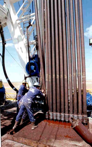
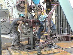
4) Using rotary slips, torque will work into the pipe; at this time, the positioning of the latched elevators is essential. Located just below the tool joint, this will allow rotation for the pipe through the elevators. While the torque is trapped in the string, elevators can be used to adjust and control the pipe. Depending on whether the blocks are secured to a guide rail system, the hook swivel will need to be Locked (if secured) or Unlocked (if not).
5) Normal procedure will see right-hand torque applied and worked downhole (to reach the planned back-off point) before applying any left-hand torque. If you had to free the drilling assembly by working the pipe hard to the right, this step isn’t a necessity.
What’s the perfect amount of right-hand torque when working down the string? There’s no universal answer, and it all depends on the wellbore profile, well depth, and degree of hole drag (torsion and tension). While locating the free point, the correct string tension also needs to be determined so it can be applied at the surface; this ensures torque is worked down to the back-off point.
With this in mind, it’s not necessarily the case that the pipe is worked between the slack-off weight and calculated pick-up weight at the back-off point. When determining the free point, the torque measurements taken provide a guide to correct surface tension not only for applying right-hand torque but left-hand torque too.
When working the torque down the pipe, it should travel from surface to the free point depth. Between the zero surface tension and calculated free pipe pick-up weight (at the back-off point), the pipe should be lowered and raised because tool joints will only torque correctly with minimum axial tension. At the same time, right-hand torque should progressively increase.
1) Generally speaking, 70% of the right-hand make-up torque is the maximum for applying left-hand torque at surface; it should never exceed this amount.
SUMMARY: A Workover Rig Floor Hand is responsible for performing services on oil wells utilizing a double, single, and Pole Rig. The duties of the floor hand include assisting in rigging up/down, pulling/laying rods, tubing, casing and other functions as specified by the rig operator.
Handle tubing, rods, casing and associated equipment such as rod strippers, polish rods, etc. The rig hand will operate rod wrenches, tongs, elevators, and associated equipment.
Must have one - two (1-2) years of experience within oil and gas workover rigs, drilling rigs, production facilities, pipeline labor or equivalent experience.
8. A trust with over $5 million in assets managed by a person capable of understanding the risks of unregistered securities is qualified. The trust’s original intent must not have been to purchase the securities offered.
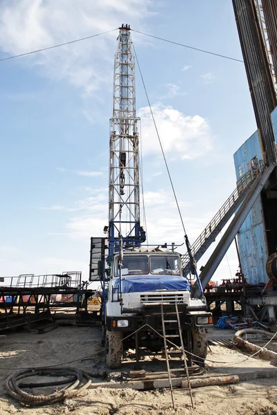
Drill Rig: The machinery that’s used to drill oil and gas wells. There are two types of drill rigs: rotary and cable tools, with rotary drill rigs being more efficient.
An internal-combustion engine frequently used for powering drilling rigs. A diesel engine is a high-compression engine that draws air into its cylinders and compresses the air to very high pressures; ignition then occurs as fuel is injected into the compressed, hot air. Combustion takes place in the cylinder above the piston; the combustion then powers the piston.
The machinery that’s used to drill oil and gas wells. There are two types of drill rigs: rotary and cable tools, with rotary drill rigs being more efficient.
A drilling rig – typically powered by diesel – where the original energy source is converted to electricity via generators. Electricity is then pumped through electrical conductors to electrical motors.
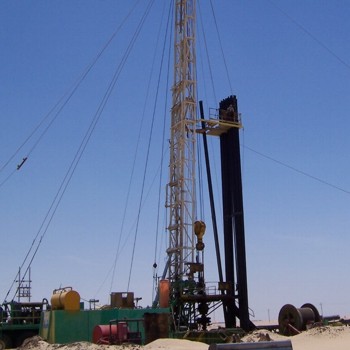
Hinged steel devices with manual operating handles that are attached to rotary and top drive rigs. Crew members latch elevators onto tool joints to operate them.
This oil recovery process that restores formation pressure and improves oil displacement can be used at any point of the productive life of an oil reservoir. There are three major types of enhanced oil recovery: chemical flooding, miscible displacement, and thermal recovery. Each recovery type alters the original properties of oil, but the specific type used is dependent on the temperature, depth, and other traits of the reservoir.
The process of injecting gas into a reservoir to maintain the pressure created by the gas drive. This process also reduces the decline rate of the original reservoir drive. There are two main types of gas injection: non-miscible oil and miscible oil injection.
A drilling technique that consists of vertical drilling down to a particular depth, and then involves turning at a right angle to drill horizontally within a specified reservoir.
The agreement formed by the owner of the property and the interested exploration and development party. The property owner gives the lessee exclusive rights to search for and extract any minerals found on the property.
A contract between the mineral owner and the company interested in drilling that gives the interested company rights to explore and produce oil and gas for a specified term. The lease is usually given for royalty payments in return.


 8613371530291