
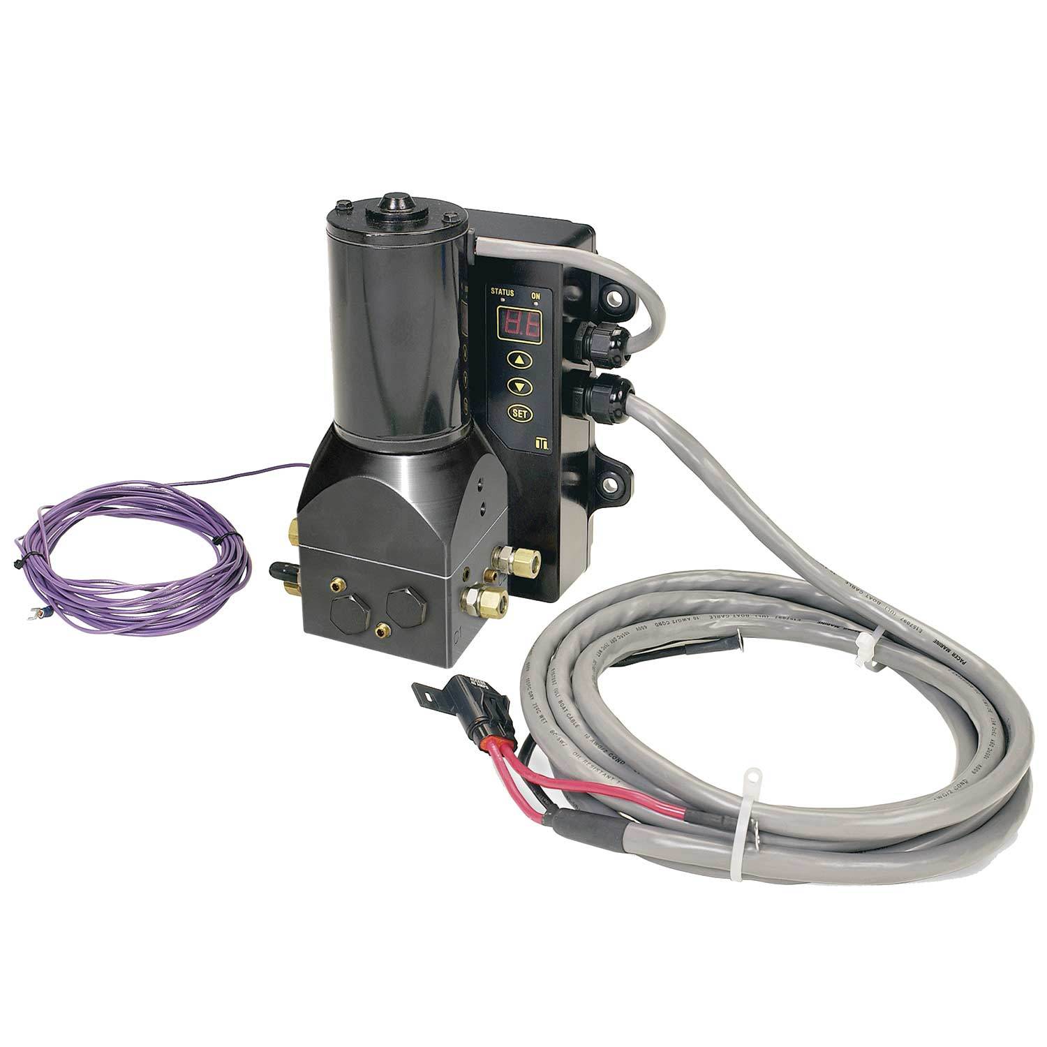
outboard hydraulic pump free sample
As outboard motors or engines are not provided with a power take-off, boats equipped with such motors are at a disadvantage when compared with boats that have inboard engines since the latter commonly have power take-offs. As a consequence, boats powered by outboard motors cannot use hydraulically operated devices such, for example, as trap and seine haulers since such motors have no means to operate a hydraulic pump.
This disadvantage has been recognized and proposals have been made to attach the drive shaft of a hydraulic pump to the fly wheel end of the drive shaft of the outboard by means of a flexible coupling with the pump housing suitably anchored. As far as we are aware, however, such proposals have not been well received because of difficulty in effecting a satisfactory connection between the shafts.
The general objectives of the present invention are to provide outboard motors with hydraulic pumps and to provide means enabling such pumps to be attached to the engines thereof with maximum ease and convenience and ensure efficient pump operation with accommodation of misalignment forces.
In accordance with the invention, these objectives are attained with the fly wheel, or the flywheel and the crankshaft of an outboard motor constituting a support by which a hydraulic pump can be driven. Each pump attachment includes a coupling by which the pump shaft is or may be connected to the support and driven thereby with the weight of the attached pump transmitted to the support. Each attachment also includes resiliently yieldable torque opposing and pump stabilizing means by which a coupled pump may be attached to the motor laterally of its fly wheel.
Another objective of the invention is to provide a coupling in which the torque opposing means accommodate the misalignment forces, an objective attained with the coupling a hub secured to the fly wheel in which the end of the pump shaft is splined and locked thereto and with at least one torque opposing arm secured to the pump and the engine with the connection including a resilient mount.
Another objective of the invention is to provide a coupling that is flexible and capable of accommodating the misalignment forces, an objective attained with the coupling having a drive member fixed on the fly wheel, a driven member locked to the pump shaft and extending through the drive member, a supporting ball joint between the driven member and the upper end of the crankshaft, and a driving connection between the members capable of accommodating misalignment forces.
A further objective of the invention is to ensure pump stability where a flexible coupling is used, an objective attained with the torque opposing means a series of at least three arms connected to or connectable to the motor at three appropriately spaced points, the arms preferably of the type having, at least one end provided with a bolt receiving eye having an elastomerid lining.
FIG. 1 is a perspective view of an outboard engine or motor with a hydraulic device operating system, the pump of which is driven by the outboard engine;
A typical outboard engine or motor having a horse power rating adequate for use by commercial fishermen is generally indicated at 10 in FIG. 1. The casing of such a motor includes an upper portion 11 which, when removed exposes the engine 12, and its fly wheel 13. The nut 14 by which the fly wheel 13 is secured to the upper end of the engine crankshaft is partly within a coaxial cylindrical recess or seat 14 within which are screw holes 16 by which a fly wheel attachment or pulley may be secured.
Hydraulic systems suitable for installation on small boats are, of course, well known. Such systems include a hydraulic pump 17, an oil chamber 18 having a hose 19 placing it in communication with the intake side of the pump 17. A hose 20 connects the discharge of its pump 17 to the four-way valve 21 having an actuator 22 by which the direction of flow through the hose lines 23 and 24 to and from the device controlling its operation in the desired manner. Such a device is indicated schematically at 25 and it may, for examples, be a pot or seine hauler, a gil net reel, a deck winch, or a power boom. The valve is also provided with a return hose 26 connected to the chamber 18 through an oil filter 27. Thus, with the pump 17 in use, oil circulates through the valve 21 or if the valve is set to operate the device 25 in one direction or the other, the circulation is through the hose lines 23 and 24 in the appropriate direction and through the return line 26.
In order to utilize the engine 12 to drive the pump 17, the pump 17 must be mounted with its drive shaft 28 connected to the fly wheel and its casing 29 secured and in accordance with the invention, attachments are provided to enable such an installation to be effected.
The pump casing 29 is detachably secured to a torque arm 36 having a port 37 through which the pump shaft 28 freely extends downwardly into the hub bore 32 which is dimensioned to receive it with a slidable connection between them, either a splined or key and keyway connection, a splined connection being shown in FIG. 3. The pump shaft 28 is locked to the hub 30 by a set screw 38 so that the fly wheel 13 is the support to which the weight of the pump 17 is transmitted with the function of the torque arm 36 that of pump stabilizing and opposing torque. To that end, the arm 36 is of sufficient length to extend beyond the periphery of the fly wheel 13 and over some part of the engine that serves as or can be easily converted into a seat 39 and provided with threaded bores 40 to enable the base of a resilient mount 41, shown as of an elastomeric type, to be secured thereto by screws 42. The mount 41 has threaded sockets 43 to enable the arm 36 to be secured thereto by screws 44 with the arm 36 held above the hub 30, in the described embodiment, the spacing effected by the height of the mount 41. With the pump 17 thus mounted, the casing 11 may be cut to accommodate it and a cap 45 that is provided fits over the pump 17 and is sealed to the casing 11.
In the embodiment of the invention illustrated by FIGS. 4-6, the fly wheel 46 and the upper end of the crankshaft 47 of the engine 48 are both used as the support for the pump 49.
The coupling of the attachment includes a flanged driving member 50 having a bore or chamber 51 extending vertically therethrough. The drive member 50 is clamped to the fly wheel 46 by screws 51. A driven member 52 is keyed to the end of the shaft 53 of the pump 49 and is also locked thereto by a set screw 54 accessible through a port 55 in the driving member 50.
The upper end of the crankshaft 47 has an axial seat 61 for a ball 62 and the lower end of the driven member 52 has a recess 63 for a seat 64 fitting the upper portion of the ball 62 so that the weight of the pump 49 is supported directly by the crankshaft 47.
The pump 49 is bolted to a holder 65 having oppositely disposed, depending flanges 66. Three torque opposing stabilizing arms 67 are provided and each has a bolt-receiving eye 68 threaded on each end. Two of the arms 67 are bolted at one end to one flange 66 adjacent the ends thereof and have their other ends bolted to a bracket 69 fixed on the engine 48 at one side of the fly wheel 46, the eyes 68 at the last named arm ends provided with elastomeric linings 70. The other arm 67 has one end bolted to the other flange 66 and its other end similarly attached to a bracket 71 fixed on the engine 48 on the opposite side of the fly wheel 46 with the eye 68 at the last named arm end also having an elastomeric lining 70.
The casing of the outboard motor of FIG. 1 has its upper portion 72 cut away and provided with a cap 73 dimensioned to accommodate the attached pump 49.

Outboard motors, stern drive units and the like employ a vertically tiltable lower propeller units which are adjustable trimmed relative to the boat and water. Generally, adjustable trimming means is required to compensate for various factors such as speed, loading, water conditions and the like. Proper trimming is desirable in order to obtain maximum speed operation while maintaining safe propulsion conditions. As various factors may vary when underway, this system desirably provides for adjustment of the trim while moving.
Generally, the support and lower units are provided with piston-cylinder units connected to a suitably pressurized fluid supply for trim adjustment. Additionally, hydraulic shock absorbing and energy dissipating piston-cylinder units are employed to permit tilt of the lower unit in response to striking of an underwater obstacle and the like without damage to the boat or motor. Further for trailering and maintenance, the propulsion device is tilted upwardly to a clearance position. Various systems have been suggested employing separate trim position units and shock absorbing units.
Generally, known functioning units suitable shock valve means connected in the system to compensate for timed energy forces under impact. For example, an energy absorbing relief valve means may be provided in the pump unit. Because of the large forces and pressures encountered, however, the size, shape, and structure of the hydraulic lines and connections becomes critical. The hydraulic system normally includes flexible lines or hoses for convenient interconnection of an inboard reservoir and pump means to the hydraulic actuator. Such lines are inherently subject to expansion and contraction under the required high pressures which may adversely affect the system operation. In addition, very large high strength lines are required. A highly desirable system employs a dual acting piston-cylinder unit for trim positioning, trailering positioning, and shock absorbing. The use of a combined shock absorbing and a trim positioning cylinder unit minimizes the number of components thereby minimizing the hardware and undesirable aesthetics associated with the multiple component systems. An extremely satisfactory system is disclosed in the copending application entitled "HYDRAULIC POWERED TRIM AND TILT APPARATUS FOR MARINE PROPULSION DEVICES" of Hale et al, which was filed on Sept. 4, 1975, the same date as this application, bearing Ser. No. 610,318 and assigned to a common assignee herewith. As more fully disclosed in such application, the combined trim, tilt, and shock absorbing means is provided mounted within the bracket assembly for aesthetic purposes and also to protect the components and particularly the hydraulic connections.
In order to permit the various functions under optimum conditions relatively complicated hydraulic systems and multiple cylinder arrangements have been generally employed.
The present invention is particularly directed to a hydraulic system for operating of a combined power trim and shock absorbing piston-cylinder unit for the tilting of the lower unit of a marine propulsion means, such as an outboard motor, a stern drive unit and the like which provides a reliable, long life protection and allowing rapid and accurated positioning of the lower units. The hydraulic supply apparatus of the present invention provides a highly favorable trail-out construction which permits movement of the propeller unit over obstructions at low speeds in a forward direction as well as addditional mechanisms permitting convenient manual tilting. Further, in accordance with a preferred and novel construction the apparatus is constructed and connected to introduce "memory" into the system such that after tilting either because of "trail-out" manual tilt or high speed impact tilting, the propulsion unit, returns to the previously set trim position.
More particularly, in accordance with the present invention, the trim and shock absorbing operator means is powered up and down from a pressurized reversible hydraulic source such as the conventional reversible pump. The source provides a trim-up port at one side and a trim-down port to the opposite side. The trim-up port is connected by a pressure responsive pilot valve means to the trim-up side of the trim and shock absorbing means to expand the unit and thereby effect the trim-up positioning. The opposite side or trim-down powered of the means is connected to return the fluid therefrom through a trim-down line including a reverse lock valve means, which is preferably an electrically operated normally open valve means providing a reverse lock functioning, and a down-pilot valve means to the supply or trim-down port of the source. The down-pilot valve means is preferably a spool type providing full flow under trim-up conditions and responsive to an increasing pressure at the trim-down side of the source to close the trim-up return path and pressurize the trim-down side of operation means through the reverse lock valve means. This provides for a full flow return path in the trim-up path and thereby avoiding the adverse effect of restrictions. With the source means establishing a trim-down output, the pilot valve means in the trim-up side of the source is actuated to positively hold the associated valve means open thereby permitting draining and return of hydraulic fluid from the opposite or trim-up side of the operator means and preventing a hydraulic lock of the operator means.
In accordance with a particular aspect of the present invention, an "up-reverse" pilot valve means having a pressure operator is connected in parallel with the reverse lock valve means. The operator is connected to the trim-up port of the source. In a trim-up mode, the "up-reverse" pilot valve means is therefore positively held open and provides a by-pass path around the reverse lock valve means which closes when in reverse gear. The valve means introduces a restriction in the flow path, thereby reducing the effective pressure applied to raise the trim and shock absorbing operator means to prevent full trim-up. When running in the reverse lock valve means is closed. The pump circuit is also positively held open to positively prevent operation of the pump and thereby preventing trim-up while running in reverse.
The apparatus also provides for automatic trailover at low speed impact movement of the lower unit by the maintaining of the return path essentially unrestricted in forward gear or neutral. However, the trim-up hydraulic side of the operator means is effectively sealed. Although the operator moves such as the expansion of a piston-cylinder unit to allow the movement of lower unit over the low impact load, hydraulic liquid is not drawn into the system on the trim-up side of the piston-cylinder unit. Consequently, after the device rides over the load, the lower unit automatically returns to the initial trim-set position, thus effecting a "memory" response. At high speed impact the flow system essentially is that described for slow impact. However, the return flow will not permit the complete free movement and consequently the cylinder pressure increases and at a selected point opens shock valves within the system and particularly within the piston assembly which absorbs the forces and prevents kicking or rapid movement of the lower unit. After high speed impact, a metered orifice and check valve means allows return to the original trim-set position as a result of the desirable memory feature.
The hydraulic supply system of the present invention as applied to a combined trim and shock absorbing cylinder unit therefore produces a highly accurate and positive control, permitting the lower unit to tilt or move upwardly under relatively safe conditions and automatically returning to the desired trim position while also permitting the high speed impact compensation essential to safe motor boating and the like. The trimming can be readily effected while under forward running conditions and to a limited degree in non-running reverse gear position. Further, the hydraulic supply system does not require any complicated control structures or the like and can be conveniently and economically manufactured while maintaining or while providing reliable operation over a long operating life.
FIG. 2 is a schematic flow diagram of a hydraulic system constructed in accordance with the teaching of the present invention for the outboard motor power trim assembly of FIG. 1;
Referring particularly to FIG. 1, a fragmentary portion of an outboard motor drive apparatus is shown to illustrate and explain a preferred embodiment of the present invention. The outboard motor apparatus generally includes an outboard motor 1 having a swivel bracket 2 pivotally attached to a transom bracket assembly 3 mounted to a transom 4 of a boat, not otherwise shown. Conventionally, swivel bracket 2 is pivotally mounted to a transom bracket on a horizontally located tilt tube or pin 5 and includes a suitable vertical pivot support for the outboard motor 1 permitting steering movement of the outboard motor in accordance with conventional practice. A powerhead 6 is secured to the upper end of drive shaft housing 7 with a lower propeller unit 8 is secured to the lower housing end. A dual function powered trim and shock absorbing piston-cylinder assembly 9 is shown mounted within the swivel and transom bracket assemblies. The illustrated swivel bracket in the power cylinder assembly is similar to that disclosed in Applicatant"s previously identified copending application and, as any suitable system can be employed, the assembly is only generally described to clearly describe the embodiment of the present invention. The assembly 9 includes a pair of piston-cylinder units 10 which are located in side-by-side relation and pivotally interconnected at the upper end to the swivel bracket 2 as at 11 and at the lower end to the transom bracket 3 as at 12.
Piston-cylinder units 10 are connected to a suitable pressurized hydraulic source which is conventionally a constant displacement reversible pump means 13 and reservoir 14 located within the boat, with an interconnecting valve and control means 15 also located within the boat and connecting the output of the pump means 13 to suitable connecting hydraulic hose to the units 10. As more fully disclosed and previously identified in the above application, the hose system preferably provides for connection through the transom bracket mounting bolts 15a to the lower ends of the cylinder units 10, which includes internal passageways to the opposite ends of the cylinder unit 10.
The present invention is particularly directed to an improved hydraulic supply and control system for proper directing of the pressurized fluid to and from the piston-cylinder units and a preferred embodiment of the present invention is schematically shown in the hydraulic and electric diagrams of FIGS. 2 and 3.
Referring particularly to FIG. 2, the pair of piston-cylinder units 10 are diagrammatically illustrated including similar cylinders 16 having a piston end connected in parallel to a trim-up line 17 and the piston rod side of the cylinders similarly connected to a trim-down line 18. Piston units 19 are mounted in each cylinder 16 and move upwardly and downwardly in response to pressure at lines 17 and 18, respectively. The respective lines 17-18 of course function as return or drain paths when not pressurized. The lines 17-18 are particularly connected through a novel valving system to the constant displacement reversible pump 13 as the source of pressurized fluid. The trim-up port 20 of pump 13 is coupled to the reservoir 14 through a relatively high pressure regulating valve 21, shown as a spring loaded check valve, and the trim-down side or port 22 is similarly connected through a relatively low pressure regulating valve 23. The trim-up pressure may, for example, be set to a maximum on the order of 31 psi while the down side may be limited to 1200 psi. In addition, free floating check valves 24 are connected between the opposite sides of the pump 13 and reservoir 14, with a filter 25 shown between the trim-down check valve 24 and the reservoir 14.
The pump trim-up port 20 is connected to the trim-up line 17 of the piston cylinder units 10 by a pilot operator pressure regulating valve unit 26, diagrammatically shown as a piston operated check valve assembly. The valve unit 26 is illustrated as including a valve housing 27 with check valve ball 28 movable into engagement with an upstream valve seat 29. Preferably a soft seat valve is used in place of the illustrated ball check valve. A spring 30 resiliently holds the ball 28 in engagement with the valve seat 29, and is set to open at a relatively low pressure on the order of 50 psi. The valve seat 29 includes an inlet passageway 31 connected to the trim-up line 20 which opens the valve to transmit pressure to the trim-up line 17. The valve unit 26 further includes a pressure responsive operator shown as a piston-cylinder type with a chamber 32 secured to the upstream side of the ball check valve housing 27 and with a piston or plunger 33 slidably mounted therein. A piston rod 34 extends into the valve inlet passageway 31 for selective engagement with the check ball 28. The pump port 20 is coupled to the operator chamber 32 to the piston rod side of the piston 33. Thus, when the pump 13 is operated to pressurize the trim-up port 20, piston 33 is withdrawn and transmits full pressure to and through valve 26. The units 10 are then powered to trim-up the outboard motor lower unit by forcing of the piston 19 outwardly of the piston cylinders 16. The fluid to the piston rod side of such units 10 is returned through trim-down line 18 which is returned to the reservoir 14 as follows.
The pilot valve means 37, which may also be a soft seat valve, is shown as a spring loaded check valve assembly having a pressure responsive operator similar to valve means 26 in the trim-up path to the piston cylinder units 10. Thus, valve means 37 includes a check ball valve 45 having an inlet port connected to line 18 and an outlet port 46 resiliently closed by a ball check 47. The pilot valve means 37 also includes a cylinder operator 48 having a central piston 49 operable to move the ball check 47 to open the valve means 37. The valve opening 46 is connected by a by-pass line 50 to the common connection between the reverse lock valve means and the down pilot pressure valve means 36. This then provides a restricted by-pass. The operator 49 has the piston side connected by a control signal line 51 to the trim-up port 20 of the pump 13 in the illustrated embodiment, in series with the valve means 26. Thus, with the pump 13 operating to pressurize the trim-up port 20, the pilot check valve means 37 is also pressurized and will positively hold the valve open and maintain the restricted flow path through orifice 46, in parallel with the closed reverse lock solenoid means 35.
When running in reverse gear, the thrust of the lower unit is applied in the direction to trim-up. However, the reverse lock solenoid valve means 35 is now positively closed. Trim-up by actuation of the pump 13 can occur with return flow occurring through valve means 37. Tilting up movement of the engine is prevented by the action of the pilot check valve means when the pump 13 is inactivated
Trim-down is affected by reverse running of the pump 13 to pressurize the trim-down port and line 20 with the following operation. The trim-down line 20 is connected to the "down" pilot pressure valve means 36 which is diagrammatically illustrated as a spool-type valve having a cylindrical valve chamber 52. An intermediate common port 53 is connected to the reverse lock valve means 35. The return port 54 for trim-up operation is connected to one end of the spool valve chamber 52 while a trim-down port 55 is connected directly to the opposite end and is also connected to pump line 22. A spool 56 is slidably mounted within the cylinder 52 with a spring 57 acting between the spool 56 and the trim-up port end to continuously bias the spool to close the trim-down port 55 and maintaining the unrestricted trim-up return flow.
When the pump 13 is operated in a reverse direction to pressurize the trim-down port 22 pressure builds within the corresponding end of chamber 52, causing the spool 56 to move against the force of the spring 57 and sequentially closing the common port connection to port 54 and then moving beyond such common port to open the connection to the trim-down port 55. The flow is from port 55 through valve 36 and then through the reverse lock valve means 35 and pilot valve means 37 in parallel to trim-down line 18, biasing the cylinder units 10 trim-down by moving of pistons 19 downwardly. This requires the liquid on the piston side of units 10 to flow out to line 17, which is in the direction to set the ball check 28 to close valve 26. The trim-down port 22 is also connected however via a coupling line 58 to the operator chamber 32 of valve means 26. Pressure in part 22 moves piston 33 and rod 34 to positively hold valve 26 open.
Thus, the trim-down line 18 to the piston-cylinder units 10 is pressurized and the piston-cylinder units 10 are actuated to move the pistons 19 and piston rods downwardly as shown in FIG. 2, to trim-down with the fluid to the opposite side of the pistons 19 returning to the low pressure side of the pump 13 via the trim-up line 17.
Trimming down in reverse gear will occur in the same manner. In the reverse gear, however, the reverse lock solenoid valve means 35 is closed. This valve is preferably a soft seat seal type valve such that as the pressure rises, limited reverse flow is premitted to the trim-down line 18. Thus, on the trim-down while in reverse gear, the output of pump 13 must increase sufficiently to move the "down" pilot pressure valve, the reverse lock valve pressure and the pressure necessary to move the trim cylinder unit against the reverse thrust. The "down" pilot pressure valve 36 is set to require a pressure in excess of 300 psi to insure the opening of the valve unit 26 prior to pressurizing of the trim-down line 18. The spool valve unit 36 when shifted to pressurize line 18 establishes an unrestricted flow and maintains full pump pressure in line 18. Normally, the total pressure must reach 300 to 600 psi in the reverse output and as previously noted, the pump is capable of producing 1200 psi.
As shown in FIG. 3, the reverse lock solenoid 38 of valve 35 is connected in series with a reverse lock switch means 58 which is coupled to the reverse gear unit 58a of the motor, the battery supply is connected to switch means 58 in parallel with the trim motor control. Thus, the pump is shown including a reversible D.C. motor 59 having forward and reverse windings connected to the battery supply in series with corresponding control switches 59a. The illustrated circuit is simplified for purposes of illustration. Thus, the system will normally provide various additional controls such as an up-limit tilt switch and the like.
In the forward gear or neutral position, the illustrated hydraulic system is such that the lower unit 8 may trail over an object or be manually lifted. Thus, with the boat moving forward and in forward gear or neutral, an impact load applied to the lower unit 8 will mechanically cause the pistons 19 and attached piston rods to move in the up-direction. The fluid to the piston rod side of the piston cylinder 16 is free to move through trim-down line 18, the normally open reverse lock valve means 35 and the free flow "down" pilot pressure valve means 36 to the reservoir 14.
However, as the pistons 19 move, fluid does not enter to the opposite side of the hydraulic system and the fluid is trapped within the up-side such that the pistons 19 position remains relatively constant. Thus, valve means 26 is pressure regulated by spring 30 which is selected to prevent the valve from opening as a result of the "trail-out" or shock absorbing movement of the piston units 19. After trailing over, the lower unit 8 drops and automatically causes the pistons 19 to return to the previous trim-set position.
The unit will also similarly function under a high speed impact with respect to normal flow. However, a high speed impact load tends to create a substantial flow, the system restricts such flows and the cylinder pressure increases. The piston units 19 of the combined trim and shock absorber unit 10 are specially formed as a two piece assembly, as more fully described with respect to FIGS. 4 and 5, to define a reservior 60 between a floating trim piston member 61 and a shock piston member 62 secured to the piston rod 63. The energy of the impact as seen by the shock rod 63, as it moves outwardly, is absorbed by the piston member 62 which includes a pair of shock valve units 64 and 65. The valved piston member 62 allows the shock forces to exist on the piston units 19 for a given length of time reacting to the force of the shock rod and resisting the rotation of motor. During the shock, hydraulic fluid is passed into the reservoir 60 via assembly 64. After the shock, the fluid is allowed to return through check valve assembly 65 in the opposite side of the piston. This allows the motor to return to its original trim position.
As shown in FIGS. 4 and 5, piston-cylinder units 10 are connected to receive and return hydraulic fluid to and from opposite sides of the piston unit 62. The lower end of the cylinder 10 is closed by a head 80 which threads thereon, while the upper end formed with an integral end wall 81 within which piston rod 62 is slidably mounted. The cylinder 10 is a double wall assembly including an inner cylinder liner or jacket 82 spaced inwardly of the cylinder 10 to define a transfer passageway 83 between opposite ends of the cylinder unit. The outer wall 10 is formed with a plurality of circumferentially spaced side wall protrusions 84 which are machined to abut the outer wall of liner 82 to accurately locate the liner and define passageways 83 therebetween. The outer end of liner 82 abuts a washer 84 adjacent the inner surface of end wall 81. Washer 84 has peripheral slots 86 defining passageways from transfer passageway 83 to the cylinder chamber and particularly to the rod side thereof. A bleed opening 87 in end wall 81 is closed by a cap screw 88.
The upper end of the cylinder unit 10 with the integral head wall 81 conjointly with the special ported lower head 80 thus minimizes the overall length of the cylinder unit 10 and creates a maximum operating or working stroke of piston unit 62 and rod 63. This is a particularly significant structure where the placement of combined power trim and shock absorbing means are to be placed within the mounted bracket assembly in order to establish a high satisfactory combined trim positioning and shock absorbing stroke of the units. This structure therefore provides a very compact assembly while maintaining reliable high powered positioning of the assembly. Further, the lower head construction permits a very convenient and protective connection of the hydraulic input/output lines. As disclosed in the previously identified application, the lower heads 80 of a pair of side-by-side units may be connected to a manifold unit 97 pivotally mounted on assembly 12 and connected to units 10 for pivoting therewith and having suitable conduits, not shown, connected to fittings 95 and 96.
Supply hoses or lines 17 and 18 each are similarly connected via hoses and bolts 15a to manifold 97 for conducting hydraulic liquid to and from the lower end of the piston cylinder units 12.
The world"s most popular hydraulic boat steering helm (HH52713) offers smooth, efficient no feedback steering for inboard and outboard applications. Super-efficient steering for today’s high performance hulls with single or multiple outboards up to 700 HP combined. It’s the OEM Choice for center consoles, cruisers and more.

Marine hydraulics has become one of the most used power- and torque delivery systems, primarily due to the highly efficient transfer of large both linear and rotary forces and torques.
At Sleipner Motor, we primarily use hydraulic systems for our stabilizing vector fins and our thruster systems, but we also manufacture hydraulic steering systems for a range of high-end yachts and work boats.
If correctly dimensioned, installed and commissioned, a hydraulic system requires little maintenance, and troubleshooting is pretty easy for personnel with a reasonable knowledge of general hydraulics. The two most important factors for trouble-free operation are:
In terms of cleanliness, this cannot be stressed enough on marine hydraulics. The most crucial factor for a problem-free operation is keeping the system clean and the oil-free from impurities.
The most common system is the open hydraulic system. The open system is characterized by having apressureless tank to which the oil is returned more or less directly. Contrary to a closed system in which the oil return is directly on the pump"s suction side. All hydraulic systems built by Sleipner Motor for our Side-Power systems are open hydraulic systems. Semi-closed and closed hydraulic systems will not be discussed further in this series of hydraulic talks.
It is essential for the lifetime and reliability of a hydraulic system that the oil stays clean and within correct temperatures to avoid excessive wear and damage to any of the components in the system. The Side-Power hydraulic system is designed to achieve this by having:
I will review my experience with these various components in a series of blog articles over the next weeks. If you wish to learn more about marine hydraulics, please do not hesitate to subscribe to the Side-Power marine blog.

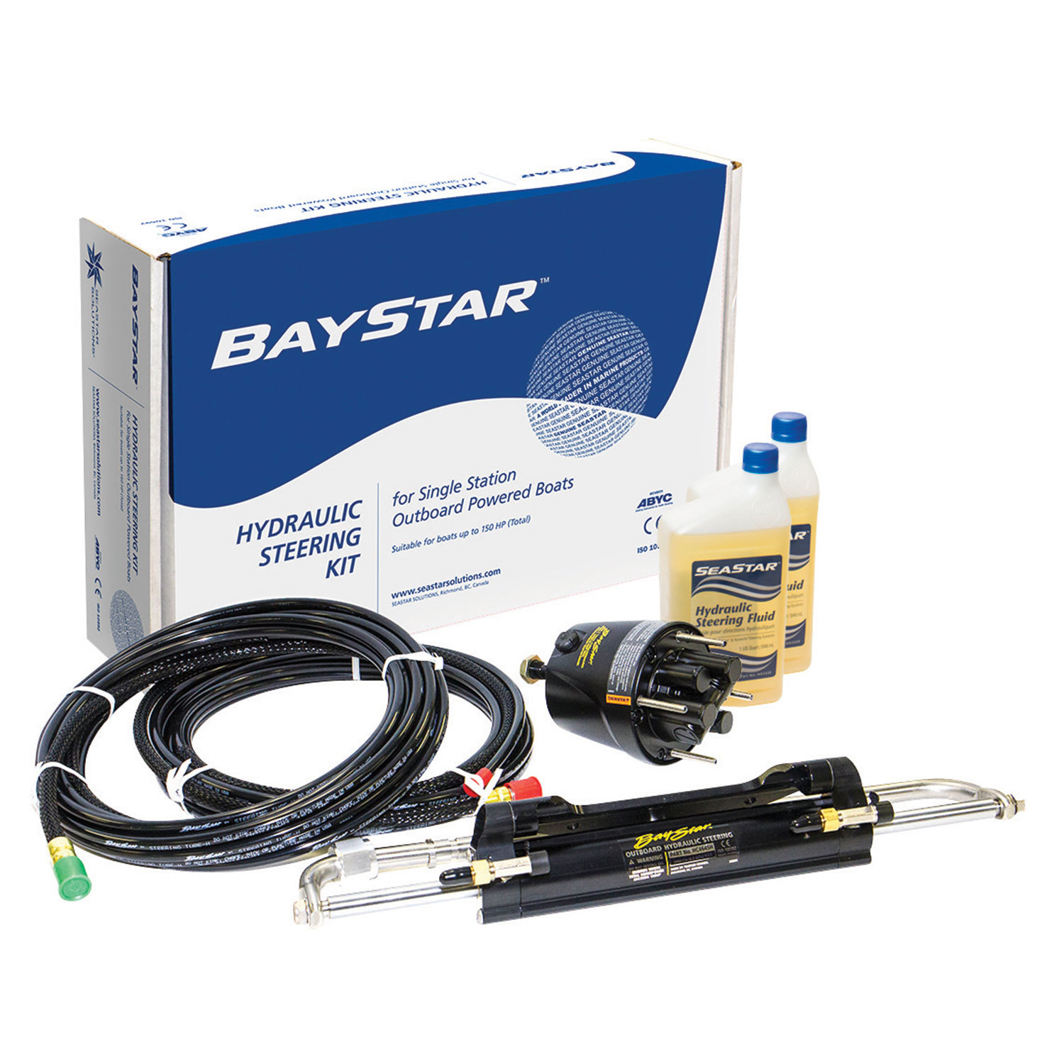
If it"s time to replace your outboard-powered boat"s mechanical steering system, consider an upgrade to hydraulic. The systems are simple, consisting of three components: an integral hydraulic-fluid reservoir with a pump at the helm, a cylinder with steering ram at the outboard, and the hydraulic lines that push the fluid between the two. The simplicity of the system reduces maintenance; the hydraulics all but eliminate steering effort. And if you"re using two hands on the wheel to steer the boat, upgrading to hydraulic steering will make it fun to drive again.
SeaStar Solutions" BayStar kit is a popular option for boaters considering a change from mechanical to hydraulic steering. This DIY project can be accomplished by a handy boater and a friend in an afternoon; or, if you decide to hire a pro to do it, just knowing how it"s done will make you a smarter boat owner. This system is designed for use with outboards up to 135 horsepower. We installed a BayStar system on a 20-foot center-console boat powered by a 115-hp outboard, replacing the boat"s original mechanical steering system that had been used in saltwater, then sat unused for several years. The effort required to turn the wheel and steer the boat was increasing with use, which a change to a hydraulic system would alleviate.
With fewer moving mechanical parts, the hydraulic system requires only periodic checks and the topping off of fluid levels, both of which are performed via an easy-access port at the helm, and annual (or every 200 hours of use) cleaning and regreasing of select cylinder and helm components. An additional benefit of moving to a hydraulic system: It gives you the option for more easily adding an autopilot. Follow these steps to make the switch to hydraulic steering.
9. Familiarize yourself with the cylinder-mounting procedure at the motor, noting where to attach each steering hose to synch the direction of the wheel swing with the proper deflection of the outboard. Have a helper ready for the mounting of the cylinder and for filling the system with hydraulic fluid. Mount the cylinder assembly to the outboard steering bracket using the stainless-steel bolt and locknut provided.
We also checked in with Aldo Mastropieri, project manager of marine steering at SeaStar Solutions, an industry leader of hydraulic steering systems in recreational boats. He reiterated all of the earlier maintenance points covered and the value of a yearly inspection or every 200 hours of operation. He said SeaStar doesn"t have a specific policy for replacing oil at regular intervals, but rather "as necessary" based on analysis of an oil sample from the reservoir. It does not go bad on its own, but if it is black or smells bad, replace the oil.
"Steering is all about how it feels," he says. How much effort does it take to steer a boat? It should not be hard or imprecise. SeaStar"s current focus is on the future of marine steering, the integration of electronics into modern steering solutions. Electrohydraulic steering is a perfected technology and the direction the industry is taking. An electronic helm steers the boat through fly-by-wire signals to turn a pump on and off, and the hydraulics are now considered the "back end" of the steering system. Drastically shorter hydraulic lines are well-protected near the rudders or engines, controlled by signals transmitted by wire from whichever helm is operational. Adding a second steering station is simply another set of wires to be run, nowhere near the complexity of traditional hydraulic steering.
Given the huge opportunity for aftermarket replacement systems, Mastropieri sees recreational boating moving away from fully hydraulic steering systems in favor of the greater control and flexibility of electrohydraulic steering.
Mastropieri commented that the company"s service center no longer recommends replacing parts in any steering system older than 10 years. As rubber ages, seals wear out and system components get hard and brittle. SeaStar advises its clients to consider replacing and/or upgrading their steering system to one of the newer solutions that use electronics. Undertaking such a project is not difficult and is a viable solution for anyone with steering issues on an older boat. It"s also within the realm of a DIY project, particularly attractive to those who own boats built in the "70s and &"80s, which are prime candidates for upgrading from older hydraulic or mechanical steering.

When a hydraulic system fails, finding the source of the problem can be a challenge. Though hydraulic systems primarily consist of a sump, motor, pump, valves, actuators and hydraulic fluid, any of these parts could be the source of failure. That"s not to mention the additional potential for failure through human error and faulty maintenance practices. If your system fails, you need to know why it fails, how to find the failure and how to keep it running smoothly in the future, all while keeping personnel safe.
It"s often easy to tell when a hydraulic system fails — symptoms can include high temperatures, low pressure readings and slow or erratic operation are glaring problems. But what are the most common causes of hydraulic systems failures? We can trace most hydraulic issues back to a few common causes, listed below.
Air and water contamination are the leading causes of hydraulic failure, accounting for 80 to 90% of hydraulic failures. Faulty pumps, system breaches or temperature issues often cause both types of contamination.
Air contamination is the entrance of air into a hydraulic system and consists of two types — aeration and cavitation. Both can cause severe damage to the hydraulic system over time by wearing down the pump and surrounding components, contaminating hydraulic fluids and even overheating the system. Although we are not pump manufacturers, we know it is essential to be aware of these types of contamination and how to identify their symptoms.
Cavitation:Hydraulic oil consists of about 9% dissolved air, which the pump can pull out and implode, causing pump problems and damage to the pump and to other components in a hydraulic system over time. You can identify this problem if your hydraulic pump is making a whining noise.
Aeration:Aeration occurs when air enters the pump cavity from an outside source. Usually, loose connections or leaks in the system cause this issue. Aeration also creates a sound when the pump is running, which sounds like knocking.
Water contamination is also a common problem in hydraulic systems, often caused by system leaks or condensation due to temperature changes. Water can degrade hydraulic components over time through oxidation and freeze damage. A milky appearance in hydraulic fluid can help you identify water contamination.
Fluid oxidization: Extreme heat can cause hydraulic fluid to oxidize and thicken. This fluid thickening can cause buildups in the system that restrict flow, but can also further reduce the ability of the system to dissipate heat.
Fluid thickening:Low temperatures increase the viscosity of hydraulic oil, making it harder for the oil to reach the pump. Putting systems under load before the oil reaches 70 degrees or more can damage the system through cavitation.
Fluid levels and quality can affect hydraulic system performance. Low fluid levels and inappropriate filtration can result in air contamination, while fluid contamination can cause temperature problems. Leaks can further exacerbate both issues.
Using the correct type of fluid is also essential, as certain hydraulic oils are compatible with specific applications. There are even oil options that offer higher resistance to temperature-related problems. Some oils even offer anti-wear and anti-foam additives to help prevent against wear and air contamination, respectively.
Human error is the base cause of many hydraulic system problems. Some of the most common errors that may result in your hydraulic pump not building pressure include the following.
Faulty installations: Improper installation of any component in a hydraulic system can result in severe errors. For example, the pump shaft may be rotating in the wrong direction, negatively affecting pressure buildup, or pipes may be incorrectly fitted, resulting in leaks.
Incompatible parts: An inexperienced installer may put mismatched components together, resulting in functional failures. For example, a pump may have a motor that runs beyond its maximum drive speed.
Improper maintenance or usage:Using systems outside their operational capabilities or failing to perform regular maintenance are some of the most common causes of hydraulic system damage, but are easy to rectify through updated maintenance policies and training.
The sources of system failures can be tricky to identify, but some hydraulic troubleshooting steps can help narrow down the options. So how do you troubleshoot a hydraulic system? Here are some of the fundamentals.
Check the pump: Take the pump assembly apart and assess all parts to ensure that they are functional and installed correctly. The most common problem areas include the pump shaft, coupling and filter.
Check the fluids:Check the level, color and viscosity of the hydraulic oil to ensure it meets specifications and has not become contaminated. Low hydraulic fluid symptoms include pressure or power loss. When in doubt, drain and replace the fluids.
Check the seals: Look for evidence of any fluid leakage around your hydraulic system"s seals, especially the shaft seal. Leakage can indicate worn-out or blown seals that can cause malfunctions with pumps, motors and control valves.
Check the filters: Ensure filters are clear of plugs and blockages. Common clogged hydraulic filter symptoms include sluggish operation and noisy operation.
Hydraulic system issues are inevitable at some point. However, simple steps can help you avoid these issues and increase the longevity of your hydraulic system. On top of effective troubleshooting, you can prevent hydraulic system failure by taking the following steps.
Follow specifications: We can trace the most common hydraulic system issues back to fundamental system problems like incompatible or improperly installed parts. For this reason, it"s essential to always double-check specifications to ensure your purchased parts can work together seamlessly.
On top of these steps, look into hydraulic system products that are specifically designed to help prevent failures. One such product is Bear-Loc® by York Precision. This innovative locking actuator is a safe, reliable feature for hydraulic components, automatically locking when sleeve pressure is relieved, preventing movement if a hydraulic system fails. This way, your can protect your personnel from injuries related to hydraulic failures. Even better, York Precision offers in-house design, engineering expertise and machining and manufacturing capabilities to produce a hydraulic locking device that meets your exact specifications.
Regularly review hydraulic system maintenance, always following manufacturer recommendations and industry best practices. Also, consider the storage condition, external influences, working pressure and usage frequency of your system to tailor your maintenance schedule and procedures.
Daily tasks:Take care of a few simple daily checks to avoid issues. For example, personnel should check the oil levels, hoses and connections and listen to the pump for abnormal sounds.
Be mindful of location:Do not stand at endpoints while working on hydraulic systems. This safety measure can help prevent loss of limb and life, as there is a lot of pressure built up in these areas that can release and result in life-threatening situations.
The best safety measures, however, are to perform excellent maintenance and use high-quality parts. If you"re looking for a quality hydraulic component manufacturer, York Precision Machining & Hydraulics can help.

Dometic Hydraulic Helm Pump HH4514-3 – Bay Star, Sea Star Plus Helm 1.4 hydraulic helm pump allows you to install all the safety, reliability and comfort of hydraulic steering in your boats with a MAXIMUM power of 150 HP. Excellent design, durability and ISO quality control. Made from very durable and high-quality materials that ensure comfort and safety!
Dometic Hydraulic Cylinder HC4645-3 Sea Star, Bay Star this outboard steering is designed to fit most engines and keep it moving. Dometic Baystar outboard hydraulic cylinders are designed for use with outboard motors up to 150 HP. The compact shape and affordable price make it part of the ideal upgrade for powerboats with engines up to 150 hp.


 8613371530291