
positive displacement hydraulic pump free sample
The Santoprene diaphragm resists cracking for a long service life and stands up to water and chemicals such as ammonium hydroxide. These pumps have a rugged aluminum housing for moving large volumes of thick sludges and slurries in demanding environments.

A positive displacement (PD) pump moves a fluid by repeatedly enclosing a fixed volume and moving it mechanically through the system. The pumping action is cyclic and can be driven by pistons, screws, gears, rollers, diaphragms or vanes.
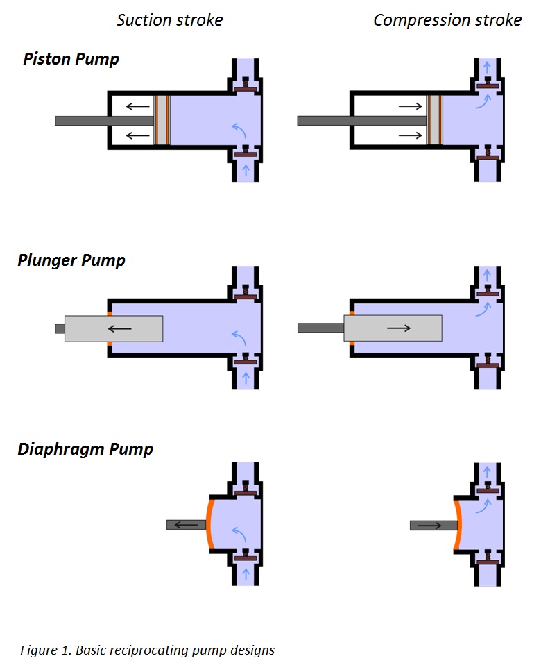
A Reciprocating Positive Displacement pump works by the repeated back-and-forth movement (strokes) of either a piston, plunger or diaphragm (Figure 1). These cycles are called reciprocation.
In a piston pump, the first stroke of the piston creates a vacuum, opens an inlet valve, closes the outlet valve and draws fluid into the piston chamber (the suction phase). As the motion of the piston reverses, the inlet valve, now under pressure, is closed and the outlet valve opens allowing the fluid contained in the piston chamber to be discharged (the compression phase). The bicycle pump is a simple example. Piston pumps can also be double acting with inlet and outlet valves on both sides of the piston. While the piston is in suction on one side, it is in compression on the other. More complex, radial versions are often used in industrial applications.
Plunger pumps operate in a similar way. The volume of fluid moved by a piston pump depends on the cylinder volume; in a plunger pump it depends on the plunger size. The seal around the piston or plunger is important to maintain the pumping action and to avoid leaks. In general, a plunger pump seal is easier to maintain since it is stationary at the top of the pump cylinder whereas the seal around a piston is repeatedly moving up and down inside the pump chamber.
A diaphragm pump uses a flexible membrane instead of a piston or plunger to move fluid. By expanding the diaphragm, the volume of the pumping chamber is increased and fluid is drawn into the pump. Compressing the diaphragm decreases the volume and expels some fluid. Diaphragm pumps have the advantage of being hermetically sealed systems making them ideal for pumping hazardous fluids.
The cyclic action of reciprocating pumps creates pulses in the discharge with the fluid accelerating during the compression phase and slowing during the suction phase. This can cause damaging vibrations in the installation and often some form of damping or smoothing is employed. Pulsing can also be minimized by using two (or more) pistons, plungers or diaphragms with one in its compression phase whilst the other is in suction.
The repeatable and predictable action of reciprocating pumps makes them ideal for applications where accurate metering or dosing is required. By altering the stroke rate or length it is possible to provide measured quantities of the pumped fluid.
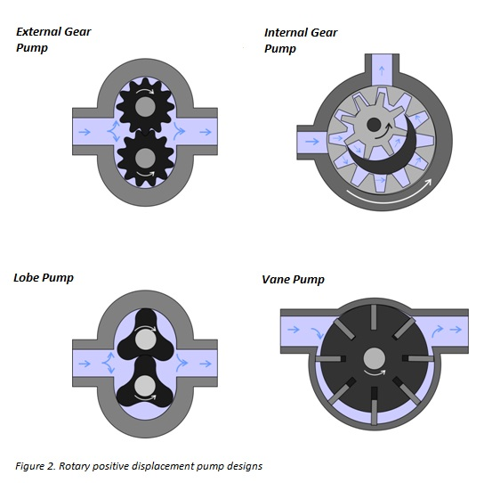
Rotary positive displacement pumps use the actions of rotating cogs or gears to transfer fluids, rather than the backwards and forwards motion of reciprocating pumps. The rotating element develops a liquid seal with the pump casing and creates suction at the pump inlet. Fluid, drawn into the pump, is enclosed within the teeth of its rotating cogs or gears and transferred to the discharge. The simplest example of a rotary positive displacement pump is the gear pump. There are two basic designs of gear pump: external and internal (Figure 2).
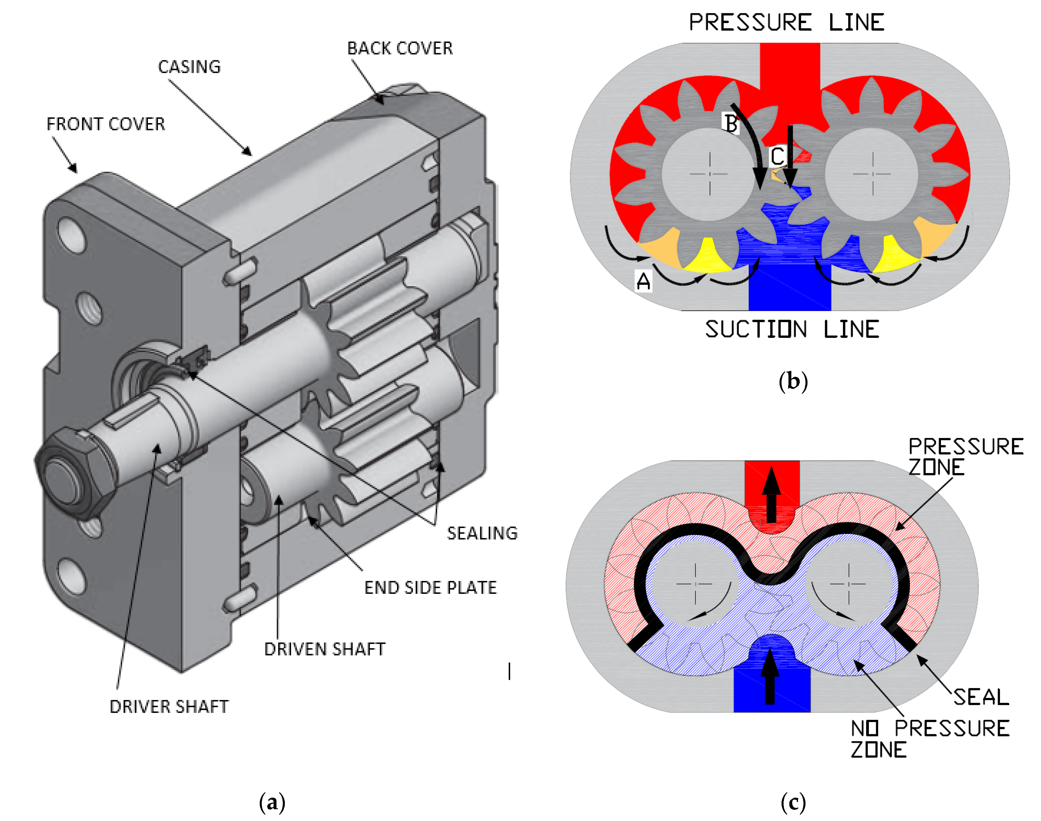
An external gear pump consists of two interlocking gears supported by separate shafts (one or both of these shafts may be driven). Rotation of the gears traps the fluid between the teeth moving it from the inlet, to the discharge, around the casing. No fluid is transferred back through the centre, between the gears, because they are interlocked. Close tolerances between the gears and the casing allow the pump to develop suction at the inlet and prevent fluid from leaking back from the discharge side. Leakage or “slippage” is more likely with low viscosity liquids.
An internal gear pump operates on the same principle but the two interlocking gears are of different sizes with one rotating inside the other. The cavities between the two gears are filled with fluid at the inlet and transported around to the discharge port, where it is expelled by the action of the smaller gear.
Gear pumps need to be lubricated by the pumped fluid and are ideal for pumping oils and other high viscosity liquids. For this reason, a gear pump should not be run dry. The close tolerances between the gears and casing mean that these types of pump are susceptible to wear when used with abrasive fluids or feeds containing entrained solids.
In the case of the lobe pump, the rotating elements are lobes instead of gears. The great advantage of this design is that the lobes do not come into contact with each other during the pumping action, reducing wear, contamination and fluid shear. Vane pumps use a set of moveable vanes (either spring-loaded, under hydraulic pressure, or flexible) mounted in an off-centre rotor. The vanes maintain a close seal against the casing wall and trapped fluid is transported to the discharge port.
A further class of rotary pumps uses one or several, meshed screws to transfer fluid along the screw axis. The basic principle of these pumps is that of the Archimedes screw, a design used for irrigation for thousands of years.
There are two main families of pumps: positive displacement and centrifugal. Centrifugal pumps are capable of higher flows and can work with lower viscosity liquids. In some chemical plants, 90% of the pumps in use will be centrifugal pumps. However, there are a number of applications for which positive displacement pumps are preferred. For example, they can handle higher viscosity fluids and can operate at high pressures and relatively low flows more efficiently. They are also more accurate when metering is an important consideration.
In general, positive displacement pumps are more complex and difficult to maintain than centrifugal pumps. They are also not capable of generating the high flow rates characteristic of centrifugal pumps.
Positive displacement pumps are less able to handle low viscosity fluids than centrifugal pumps. To generate suction and reduce slippage and leaks, a rotary pump relies on the seal between its rotating elements and the pump housing. This is considerably reduced with low viscosity fluids. Similarly, it is more difficult to prevent slippage from the valves in a reciprocating pump with a low viscosity feed because of the high pressures generated during the pumping action.
A pulsing discharge is also a characteristic of positive displacement, and especially reciprocating, pump designs. Pulsation can cause noise and vibration in pipe systems and cavitation problems which can ultimately lead to damage or failure. Pulsing can be reduced by the use of multiple pump cylinders and pulsation dampeners but this requires careful system design. Centrifugal pumps, on the other hand, produce a smooth constant flow.
The back-and-forth motion of a reciprocating pump can also be a source of vibration and noise. It is therefore important to construct very strong foundations for this type of pump. As a consequence of the high pressures generated during the pumping cycle it is also vital that either the pump or discharge line has some form of pressure relief in case of a blockage. Centrifugal pumps do not need over-pressure protection: fluid is simply recirculated in this eventuality.
Feeds containing a high level of abrasive solids can cause excessive wear on the components of all types of pumps and especially valves and seals. Although the components of positive displacement pumps operate at considerably lower speeds than those of centrifugal pumps, they remain prone to these problems. This is particularly the case with piston and plunger style reciprocating pumps and gear rotary pumps. With this type of feed, a lobe, screw or diaphragm pump may be suitable for more demanding applications.
Positive Displacement pumps are commonly used for pumping high viscosity fluids such as oil, paints, resins or foodstuffs. They are preferred in any application where accurate dosing or high pressure output is required. Unlike centrifugal pumps, the output of a positive displacement pump is not affected by pressure so they also tend to be preferred in any situation where the supply is irregular. Most are self priming.
A positive displacement pump moves a fluid by repeatedly enclosing a fixed volume, with the aid of seals or valves, and moving it mechanically through the system. The pumping action is cyclic and can be driven by pistons, screws, gears, lobes, diaphragms or vanes. There are two main types: reciprocating and rotary.
Positive displacement pumps are preferred for applications involving highly viscous fluids such as thick oils and slurries, especially at high pressures, for complex feeds such as emulsions, foodstuffs or biological fluids, and also when accurate dosing is required.

Liquid is allowed to flow into the pump as the cavity on the suction side expands and the liquid is forced out of the discharge as the cavity collapses. This principle applies to all types of Positive Displacement Pumps whether the pump is a rotary lobe, gear within a gear, piston, diaphragm, screw, progressing cavity, etc.
A Positive Displacement Pump cannot be operated against a closed valve on the discharge side of the pump, i.e. it does not have a shut-off head like a Centrifugal Pump does. If a Positive Displacement Pump is allowed to operate against a closed discharge valve it will continue to produce flow which will increase the pressure in the discharge line until either the line bursts or the pump is severely damaged or both.
Börger Rotary Lobe Pumps are self-priming, valveless, positive displacement pumps. Two synchronized rotors rotating against each other build chambers towards the pump casing. At the suction side the open chambers fill with the conveyed product. The product is displaced in the direction of the volume flow into the discharge side. The capacity is speed related and the flow is reversible. At standstill the rotors the pump nearly perfect seal.
For the customer, capital cost, energy consumption, maintenance and downtime as well as replacement part pricing levels compare excellently with all other displacement pumps.
The quench and control liquid filled intermediate chamber, between the pump casing and the timing gear, provides a high degree of safety and is supplied by Börger as standard.
Supplied as standard with strong mechanical seal in different constructions and materials, optional with multiseal or packing. The new DPL size double-acting mechanical seal is especially designed for pumping difficult and hazardous, often viscous media.
In this type of pump, fluid is carried between gear teeth and displaced when they mesh. The surfaces of the rotors cooperate to provide continuous sealing and either rotor is capable of driving the other.
One gear is driven by the shaft coupled to a driver. This gear drives the other gear. The rotation of the gears is such that the liquid comes into the inlet port and flows into and around the outer periphery of the two rotating gears. As the liquid comes around the periphery it is discharged to the outlet port. The flow of the pump is regulated by the size of the cavity (volume) between the teeth and the speed of the gears.
Slippage approaches zero at 5000 SSU. As the viscosity increases, the pump speed is lowered to allow the liquid to fill the space between the rotating teeth.
Most external gear pumps use spur, helical, or herringbone gears. The helical and herringbone gears will deliver more flow and higher pressure. They are quieter than the spur gears but may require more net inlet pressure than a spur gear.
The most common uses for these pumps are to supply fuel oil for burners, gasoline transfer, kerosene, fuel oil, and diesel oil. They are used for hydraulic devices such as elevators and damper controls. They also pump coolants, paints, bleaches, solvents, syrups, glues, lard, greases, asphalt, petroleum, and lube oils and are used in general industrial applications.
External gear pumps can handle small suspended solids in abrasive applications but will gradually wear and lose performance. Materials of construction are dictated by the application and are available in cast iron, ductile iron, bronze, cast steel, and stainless steel. Because of their broad application scope, numerous optional designs are available.
Rated (normal) performance range is 1 to 180 m3/h (5 to 800 gpm), 3.5 to 21 bar (50 to 300 psi), and 0.37 to 75 kW (0.5 to 100 hp). Small external gear pumps frequently operate at four-pole motor speeds (1800 rpm) and have operated at two-pole speeds (3600 rpm). As the pump capacity per revolution increases, speeds are reduced to less than 500 rpm. Operating speeds and flow rates are reduced as the fluid viscosity increases.
The internal gear pump is a rotary flow positive displacement pump design, which is well-suited for a wide range of applications due to its relatively low speed and inlet pressure requirements.
They are often a more efficient alternative than a centrifugal pump, especially as viscosity increases. Internal gear pumps have one gear with internally cut gear teeth that mesh with the other gear that has externally cut gear teeth. Pumps of this type are made with or without a crescent-shaped partition. Either gear is capable of driving the other, and the design can be operated in either direction. Designs are available to provide the same direction of flow regardless of the direction of shaft rotation.
As the gears come out of mesh on the inlet side, liquid is drawn into the pump. The gears have a fairly long time to come out of mesh allowing for favorable filling. The mechanical contacts between the gears form a part of the moving fluid seal between the inlet and outlet ports. The liquid is forced out the discharge port by the meshing of the gears.
Internal gear pumps are commercially available in product families with flows from 1 to 340 m3/h (5 to 1500 gpm) and discharge pressures to 16 bar (230 psi) for applications covering a viscosity range of 2 to 400,000 cSt (40 to 2,000,000 SSU). Internal gear pumps are made to close tolerances and typically contain at least one bushing in the fluid. They can be damaged when pumping large solids. They can handle small suspended solids in abrasive applications but will gradually wear and lose performance. Materials of construction are dictated by the application and include cast iron, ductile iron, bronze, cast steel, and stainless steel.
Small internal gear pumps frequently operate at four-pole motor speeds (1800 rpm) and have operated at two-pole speeds (3600 rpm). As the pump capacity per revolution increases, speeds are reduced. Larger internal gear pumps typically operate below 500 rpm. Operating speeds and flow rates are reduced as the fluid viscosity increases.
Pinion-drive internal gear pumps are a distinctive subclass with unique operating characteristics. They are typically direct-drive arrangements operating at two-, four-, and six-pole speeds for flows below 750 L/min (200 gpm) on clear to very light abrasion, low-viscosity, hydrocarbon-based fluids. They are available in single or multistage module designs capable of pressures to 265 bar (4000 psi).
Internal gear pumps are applied in petrochemical, marine, terminal unloading, asphalt, chemical, and general industrial applications for transfer, lubrication, processing, and low-pressure hydraulics handling a wide range of fuel oils, lube oils, and viscous chemicals (both corrosive and noncorrosive). Because of their broad application scope, numerous optional designs are available, such as close-coupled, abrasion resistant, and API Standard compliance considerations.

A Positive Displacement Pump has an expanding cavity on the suction side and a decreasing cavity on the discharge side. Liquid flows into the pumps as the cavity on the suction side expands and the liquid flows out of the discharge as the cavity collapses. The volume is a constant given each cycle of operation.
A Positive Displacement Pump, unlike a Centrifugal or Roto-dynamic Pump, will produce the same flow at a given speed (RPM) no matter the discharge pressure. A Positive Displacement Pumps is a "constant flow machine"
A Positive Displacement Pump must never operate against closed valves on the discharge side of the pump - it has no shut-off head like Centrifugal Pumps. A Positive Displacement Pump operating against closed discharge valves continues to produce flow until the pressure in the discharge line is increased until the line bursts or the pump is severely damaged - or both.
A relief or safety valve on the discharge side of the Positive Displacement Pump is absolute necessary. The relief valve can be internal or external the pump. An internal valve should in general only be used as a safety precaution. An external relief valve installed in the discharge line with a return line back to the suction line or supply tank is highly recommended.
Plunger pumps consists of a cylinder with a reciprocating plunger in it. In the head of the cylinder the suction and discharge valves are mounted. In the suction stroke the plunger retracts and the suction valves opens causing suction of fluid into the cylinder. In the forward stroke the plunger push the liquid out the discharge valve.
In a diaphragm pump the plunger pressurizes hydraulic oil which is used to flex a diaphragm in the pumping cylinder. Diaphragm pumps are used to pump hazardous and toxic fluids.
The viscosity of fuel oil nr. 2 at 20 oC is about 150 SSU. The viscoity of fuel oil type 5 at 100 oC is about 4000 SSU. According the table above the speed of the reciprocating pump should be reduced with approximately 30%.
In a gear pump the liquid is trapped by the opening between the gear teeth of two identical gears and the chasing of the pump on the suction side. On the pressure side the fluid is squeezed out when the teeth of the two gears are rotated against each other.
A progressive cavity pump consist of a metal rotor rotating within an elastomer-lined or elastic stator. When the rotor turns progressive chambers from suction end to discharge end are formed between the rotor and stator, moving the fluid.
A Positive Displacement pump (PD pump) is a mechanical device which displaces a known quantity of liquid for every revolution or cycle that the pump completes. The flow rate through a positive displacement pump is directly proportional to its speed and number of cycles over a given time.
A positive displacement pump works by using a screw, a blade, a vane, a lobe, a gear or diaphragm. It creates a chamber or cavity between the pumping elements and the cavity in which the fluid is temporarily stored is moved by the reciprocating or rotary motion along the pipe to its destination.
Progressive Cavity Pump has a rotor rotating within a housing called a stator. The rotor is always metallic and the stator is made up of a rubber type of material. It looks somewhat like a screw thread – the fluid is between the cavities and the rotary motion of the rotor forces the fluid through from one end to the other. It has a low to moderate capacity, low to high pressure, good solids handling capability, one seal, low shear, constant flow and a low pulsation.
Rotary Lobe Pumphas moderate to high capacity, low to moderate pressure, good solids handling capability, two/four seals, a constant flow and moderate pulsation.
Screw Pump –the screw pump has multi versions known as multi screw pumps featuring moderate to high capacity, high pressures, only lubricative liquids, no solids handling capability, one seal and a constant flow.
Diaphragm Pump – Air Operated Diaphragm Pump has low to moderate capacity, low to moderate pressure, very low efficiencies, no seal and high pulsation.
Positive Displacement pumps are generally used for fluids with a relatively high viscosity. They can be used where high accuracy is required e.g metering or dosing. They can also be used where high pressures are required i.e high pressure washing. Waste Water Treatment is another application e.g Netzsch Tornado Rotary Lobe Pump
The main advantages of a Positive Displacement Pump is that it can handle highly viscous fluids whereas a Centrifugal Pump would be inefficient and require high driver powers. PD pumps also have a good volumetric efficiency & driver power is kept to a minimum. The flow rate is easily adjustable via a speed control because the flow rate is directly proportional to its speed. Driver sizing is not as critical as with a Centrifugal pump because the pump will deliver the known quantity of fluids regardless of system back pressure (losses). A Positive Displacement Pump can produce a very low shear action in the case of sensitive fluids.
The main disadvantages of a Positive Displacement Pump vs a Centrifugal pump is that dry running can be catastrophic due to either close clearances of parts or in the case of progressive cavity pumps the interference fit between the rotor and stator. All PD pumps require the installation of a pressure relief valve to prevent failure of the pump or piping in case of accident or closure of the delivery valve or blockage in the piping. Main pd pumps will produce pulsations which can lead to undesirable effects i.e vibration, product damage & water hammer. PD pumps have a limited flow range ~1000m³/hr vs 180,000m³/hr Centrifugal Pumps. The material of construction of PD pumps are more limited in range of available materials than that of Centrifugal Pumps and finally PD pumps have limited solids handling ability in terms of size and/or content.
A Positive Displacement Pump will usually self-prime due to the very small clearances which exist within the pump. This will help it pull a vacuum and thus expel the air through the pump until the liquid reaches the pump. Care should be taken on the suction line i.e installation of a “goose neck” which will ensure there is some liquid in the pump during the priming cycle which will prevent dry running & consequently failure.
An Air Operated Diaphragm pump (AODD pump) is able to self-prime without any liquid being present but this capability to lift is limited if the line is empty of fluid.
Certain Positive Displacement Pumps can run dry i.e Air Operated Diaphragm pumps have no parts requiring lubrication or no close clearances between parts. Peristaltic pumps can run dry as the hose is lubricated in a bath of its own fluid. Other types of PD pumps should not be run dry.
Every pump has a NPSH (Net pressure suction head) required to ensure reliable and trouble-free operation without damage caused by cavitation therefore therefore the system should be designed to ensure there is a sufficient margin between NPSHA (Net pressure suction head available) and NPSHR (Net pressure suction head required).
Unlike a centrifugal pump which produces pressure, a positive displacement pump does not produce pressure – it is the system itself that develops pressure from the pressure drop which then creates a back pressure which largely depends on the flow rate through the system i.e higher flow rates will result in higher losses and as a result a higher back pressure. The back pressure is also dependent on the pressure in the vessel at the point of discharge i.e a hydrogen blanket present or steam. The pressure is controlled largely by the pumping rate, therefore, pressure is controlled by varying the speed of the pump. In cases where the variable speed drive is not deployed the system pressure will be controlled to a degree by the setting of the pressure relief valve.
Positive Displacement Metering pumps are usually used where a high degree of accuracy is required e.g in dosing applications where pH control is required e.g Waste Water Treatment Plants or where filling lines require accuracy of volumes of fluid dispersed into containers.
Flexachem are the leading distributors for Netzsch Positive Displacements Pumps in Ireland – Progressive Cavity Pump, Rotary Lobe Pump (Industrial applications) & Screw Pump. We also supply Inoxpa Sanitary Rotary Lobe Pump and Flotronic Air Operated Diaphragm Pumps for the Food & Beverage & Pharma sectors.
We provide localised technical support & on-site service engineering to support the operational needs of our clients. We also hold a heavily stocked inventory to help take the pressure off you in the event of unexpected emergencies. Why not contact one of our Pump Specialists if you have a particular application in mind.

A Liberty Process progressive cavity pump ideal for liquids with higher viscosities or thickness. A progressive cavity pump will have about the same flow for any liquid viscosity. The mechanical efficiency and volumetric efficiency goes up when the viscosity increases, with lower power and more flow. If you have a pumping application where you need a constant flow, but the liquid viscosity is variable and will change, then the PC pump is an ideal choice.
A progressive cavity pump is good when the application requires a varied flow. A progressive cavity pump has a precise flow per revolution of the pump. It is therefore quite easy to regulate the pump flow by just simply regulating the pump speed. Modern pump speed controllers like variable frequency drives (VFD’s) are well suited to be used with progressive cavity pumps for varying pump speed and flow control.
Another good application for a progressive cavity pump is when the suction conditions of the pumping applications are not ideal. A progressive cavity pump requires much lower Net Positive Suction Head (NPSH) as compared to a centrifugal pump because the internal pump velocity is lower. A progressive cavity pump can pump when the suction pressure is as low as 28″ of mercury (Hg), a centrifugal pump cannot do this. A progressive cavity pump will easily fill and pump in difficult applications when a centrifugal pump will not.
Progressive cavity pumps are ideal for applications where the liquid is sheer sensitive again because of lower internal velocity. A good example would be pumping oil and water mixtures to separation devices. The separation device works much better when the oil droplets are larger. A progressive cavity pump will not change the oil droplets where a centrifugal pump will emulsify the oil and make the oil droplets very small and reduce the separation performance of the separator.
A progressive cavity pump is good to use when the liquid contains abrasive solids. Most other types of positive displacement pumps can’t pump solids very well or for very long due to their close tolerances and all metal designs. A gear pump or vane pump will simply wear out when solids are present in the liquid and the same would also happen to most centrifugal pumps and they could clog. A progressive cavity pump is designed to last longer than all other pumps on abrasive applications. The pump design with the rotor and stator is the heart of the pump design for abrasion resistance. The internal velocity of the liquid as it travels through the pump is much lower than other types of positive displacement pumps and centrifugal pumps and the rubber stator.

If you need to move liquid material from one place to another, you’re going to need a pump. Industrial pumps come in two different types: centrifugal pumps and positive displacement pumps. Each type has unique properties concerning efficiency,flow rate, viscosity, and pressure. Here’s what you need to know about centrifugal and positive displacement pumps so you can choose the right application for your needs.
Centrifugal pumps are some of the most widely-used pumps in industrial settings. And they have many benefits that make them popular options. These include the following.
Various shapes and sizes —Centrifugal pumps come in avariety of sizes, meaning they are suitable for different applications and can work when you have small space constraints.
Apositive displacement pumptransports fluids by trapping a portion of the fluid and forcing it into a discharge pipe. Two or three spindles moving in opposite directions create the function of pumping, trapping, and displacing the liquid. There are several types of positive displacement pumps, including the following.
Rotary positive displacement pumpsuse a rotating mechanism to create a vacuum that draws in and captures fluid. Common examples include gear, screw, vane, peristaltic, rotary lobe, and progressive cavity pumps. Progressive cavity pumps are used in challenging applications to transfer highly viscous fluids or those containing solids, such as dirt, grit, or sludge.
Reciprocating positive displacement pumpsuse one or more oscillating pistons, plungers, or diaphragms. Valves restrict the fluid’s motion to the correct direction. Reciprocating positive displacement pumps are typically used for applications that need to maintain low flow rates against high resistance. Some may be used to pump highly viscous and heavy fluids, like sludge and slurry. Diaphragm valves are often used when pumping toxic and hazardous fluids.
Bothcentrifugal and positive displacementpumpsmove fluidsfrom one point to another. But there are quite a few differences between the two. These include:
The primary difference betweencentrifugal and positive displacementpumps is in their mechanics or how they operate. As previously described, centrifugal pumps transmit velocity to the liquid, creating pressure at the outlet.
PD pumpstrap a certain amount of liquid within thepump and transferit to the discharge port. To sum it up, centrifugal pumps create pressure, which results in flow. And positive displacement pumps create a flow that results in pressure.
Because the flow results from pressure with centrifugal pumps, you can change theflow rateby varying the pressure. Since positive displacementpumps workthe opposite of this, you’ll get consistent flow from them even with varying pressure.
You can regulate the flow in both types of pumps by changing the speed. Theflow rateis proportional to the pump’s speed with positive displacement pumps. With centrifugal pumps, you can control thepump’s operationwithout pump throttling or liquid treatment.
Centrifugal pumps become less efficient as the material being pumped’sviscosity increases. This is caused by frictional losses inside the pump. Because of this, these pumps are generally not appropriate forhighly viscous fluids(over 850 cSt). However, positive displacement pumps become more efficient with increases.
Liquids must be inside a centrifugal pump to produce a pressure differential. This is also needed because the pump can’t self-prime and can’t deliver a Gas Volume Fraction (GVF) higher than 15%. But negative pressure is created on the inlet port of positive displacement pumps. The pump needs to be filled with liquid one time, but it is self-priming and can handle large quantities of gas.
Thehigh-speedmotor used in centrifugal pumps can cause shearing of liquids, which may not be desirable for some applications. Because positive displacement pumps produce low internal velocity, little shear is created, making them more suitable for shear-sensitive materials.
Standard centrifugal pumps cannot producesuction lift. But self-priming designs are available where this is possible. With positive displacement pumps, a vacuum is created on the inlet side, so asuction liftis possible.
Centrifugal pumps achieve efficiency peaks at a particular pressure, and any variations will drastically impactpump efficiency. Operation when off the middle of the efficiency curve can cause pump cavitation and damage. The efficiency of positive displacement pumps is less affected by pressure. These pumps can be run at any point on their curve without efficiency loss or damage.
Centrifugal pumps are excellent for pumping thin liquids with low viscosity levels. This includes thin fuels and oils, many chemicals, and water. They are commonly used inhigh-volumepump applications that requirehigh flow ratesat low pressures. Some frequent uses for these pumps include the following.
Positive displacement pumps are excellent for pumping viscous fluids, such as oil, paint, and resin, athigh pressureand lowflow rates. You’ll often find positive displacement pumps in the following environments.
Each type of positive displacement pump has unique characteristics that make them ideal for particular applications. For example, lobe pumps have low shear and are easy to clean and sterilize, which makes them ideal for pharmaceutical and food processing. On the other hand, diaphragm pumps are self-priming and designed for low flows and high pressures, which makes them great for metering or dispensing oil and corrosive liquids.
Complex facilities such as manufacturing and food processing plants often benefit from using a mix of bothpump types. For example, a food processing plant may need a centrifugal pump to add water to its systems and a positive displacement pump to move thicker materials.
Whether your business needs a centrifugal pump or a positive displacement pump, find out how C&B Equipment can help. We provide qualityindustrial pumps and servicesto clients throughout Kansas, Oklahoma, Missouri, Arkansas, and the Texas Panhandle.
C&B Equipment sells a wide variety of industrial pumps to meet your operation’s specific needs and goals. We also keep you running stronger and longer with our diagnostic, maintenance, and repair services. Contact us today to learn more about our products and services.

A hydraulic pump converts mechanical energy into fluid power. It"s used in hydraulic systems to perform work, such as lifting heavy loads in excavators or jacks to being used in hydraulic splitters. This article focuses on how hydraulic pumps operate, different types of hydraulic pumps, and their applications.
A hydraulic pump operates on positive displacement, where a confined fluid is subjected to pressure using a reciprocating or rotary action. The pump"s driving force is supplied by a prime mover, such as an electric motor, internal combustion engine, human labor (Figure 1), or compressed air (Figure 2), which drives the impeller, gear (Figure 3), or vane to create a flow of fluid within the pump"s housing.
A hydraulic pump’s mechanical action creates a vacuum at the pump’s inlet, which allows atmospheric pressure to force fluid into the pump. The drawn in fluid creates a vacuum at the inlet chamber, which allows the fluid to then be forced towards the outlet at a high pressure.
Vane pump:Vanes are pushed outwards by centrifugal force and pushed back into the rotor as they move past the pump inlet and outlet, generating fluid flow and pressure.
Piston pump:A piston is moved back and forth within a cylinder, creating chambers of varying size that draw in and compress fluid, generating fluid flow and pressure.
A hydraulic pump"s performance is determined by the size and shape of the pump"s internal chambers, the speed at which the pump operates, and the power supplied to the pump. Hydraulic pumps use an incompressible fluid, usually petroleum oil or a food-safe alternative, as the working fluid. The fluid must have lubrication properties and be able to operate at high temperatures. The type of fluid used may depend on safety requirements, such as fire resistance or food preparation.
Air hydraulic pump:These pumps have a compact design and do not require an external power source. However, a reliable source of compressed air is necessary and is limited by the supply pressure of compressed air.
Electric hydraulic pump:They have a reliable and efficient power source and can be easily integrated into existing systems. However, these pumps require a constant power source, may be affected by power outages, and require additional electrical safety measures. Also, they have a higher upfront cost than other pump types.
Gas-powered hydraulic pump:Gas-powered pumps are portable hydraulic pumps which are easy to use in outdoor and remote environments. However, they are limited by fuel supply, have higher emissions compared to other hydraulic pumps, and the fuel systems require regular maintenance.
Manual hydraulic pump:They are easy to transport and do not require a power source. However, they are limited by the operator’s physical ability, have a lower flow rate than other hydraulic pump types, and may require extra time to complete tasks.
Hydraulic hand pump:Hydraulic hand pumps are suitable for small-scale, and low-pressure applications and typically cost less than hydraulic foot pumps.
Hydraulic foot pump:Hydraulic foot pumps are suitable for heavy-duty and high-pressure applications and require less effort than hydraulic hand pumps.
Hydraulic pumps can be single-acting or double-acting. Single-acting pumps have a single port that hydraulic fluid enters to extend the pump’s cylinder. Double-acting pumps have two ports, one for extending the cylinder and one for retracting the cylinder.
Single-acting:With single-acting hydraulic pumps, the cylinder extends when hydraulic fluid enters it. The cylinder will retract with a spring, with gravity, or from the load.
Double-acting:With double-acting hydraulic pumps, the cylinder retracts when hydraulic fluid enters the top port. The cylinder goes back to its starting position.
Single-acting:Single-acting hydraulic pumps are suitable for simple applications that only need linear movement in one direction. For example, such as lifting an object or pressing a load.
Double-acting:Double-acting hydraulic pumps are for applications that need precise linear movement in two directions, such as elevators and forklifts.
Pressure:Hydraulic gear pumps and hydraulic vane pumps are suitable for low-pressure applications, and hydraulic piston pumps are suitable for high-pressure applications.
Cost:Gear pumps are the least expensive to purchase and maintain, whereas piston pumps are the most expensive. Vane pumps land somewhere between the other two in cost.
Efficiency:Gear pumps are the least efficient. They typically have 80% efficiency, meaning 10 mechanical horsepower turns into 8 hydraulic horsepower. Vane pumps are more efficient than gear pumps, and piston pumps are the most efficient with up to 95% efficiency.
Automotive industry:In the automotive industry, hydraulic pumps are combined with jacks and engine hoists for lifting vehicles, platforms, heavy loads, and pulling engines.
Process and manufacturing:Heavy-duty hydraulic pumps are used for driving and tapping applications, turning heavy valves, tightening, and expanding applications.
Despite the different pump mechanism types in hydraulic pumps, they are categorized based on size (pressure output) and driving force (manual, air, electric, and fuel-powered). There are several parameters to consider while selecting the right hydraulic pump for an application. The most important parameters are described below:
Speed of operation: If it is a manual hydraulic pump, should it be a single-speed or double-speed? How much volume of fluid per handle stroke? When using a powered hydraulic pump, how much volume per minute? Air, gas, and electric-powered hydraulic pumps are useful for high-volume flows.
Portability: Manual hand hydraulic pumps are usually portable but with lower output, while fuel power has high-output pressure but stationary for remote operations in places without electricity. Electric hydraulic pumps can be both mobile and stationary, as well as air hydraulic pumps. Air hydraulic pumps require compressed air at the operation site.
Operating temperature: The application operating temperature can affect the size of the oil reservoir needed, the type of fluid, and the materials used for the pump components. The oil is the operating fluid but also serves as a cooling liquid in heavy-duty hydraulic pumps.
Operating noise: Consider if the environment has a noise requirement. A hydraulic pump with a fuel engine will generate a higher noise than an electric hydraulic pump of the same size.
Spark-free: Should the hydraulic pump be spark-free due to a possible explosive environment? Remember, most operating fluids are derivatives of petroleum oil, but there are spark-free options.
A hydraulic pump transforms mechanical energy into fluid energy. A relatively low amount of input power can turn into a large amount of output power for lifting heavy loads.
A hydraulic pump works by using mechanical energy to pressurize fluid in a closed system. This pressurized fluid is then used to drive machinery such as excavators, presses, and lifts.
A hydraulic ram pump leverages the energy of falling water to move water to a higher height without the usage of external power. It is made up of a valve, a pressure chamber, and inlet and exit pipes.
A water pump moves water from one area to another, whereas a hydraulic pump"s purpose is to overcome a pressure that is dependent on a load, like a heavy car.

Positive Displacement pumps are generally used for specialist applications such as for pumping viscous liquids or liquids that contain suspended or fragile solids. These pumps are typically not capable of such a high flow rate as say, a centifrugal pump, but they are capable of producing much higher pressures.
A positive displacement pump makes a fluid move by trapping a fixed amount of the fluid and forcing (displacing) that trapped volume into a discharge pipe or discharge system.
Some positive displacement pumps use an expanding cavity on the suction side and a decreasing cavity on the discharge side. Liquid flows into the pump as the cavity on the suction side expands and the liquid flows out of the discharge as the cavity collapses. The volume remains constant through each cycle of pump operation.
Positive Displacement pumps do not use impellers, but rely on rotating or reciprocating parts to directly push the liquid in an enclosed cavity, until enough pressure is built up to move the liquid into the discharge system. The pump does not rely on raising the velocity of the fluid as the centrifugal pump does by moving the liquid through the impeller. Consequently, the fluid velocity inside a positive displacement pump is much lower than that of a centrifugal pump. This is often a desirable feature for certain applications, such as when needing to pump a media containing fragile solids.
Positive displacement pumps, unlike centifrugal or roto-dynamic pumps can theoretically produce the same flow at a given speed (RPM) no matter what the discharge pressure. Therefore, positive displacement pumps can be regarded as constant flow devices. However, a slight increase in internal leakage as the pressure increases can prevent a truly constant flow rate.
In application, a positive displacement pump must not be allowed to operate against a closed valve on the discharge side of the pump, because it has no shutoff head like a centrifugal pump. With the pump operating against a closed discharge valve, it will continue to produce flow and the pressure in the discharge line will increase until the pipeline can either fracture or the pump can become severely damaged, or both.
To prevent this, a relief or safety valve on the discharge side of the positive displacement pump is therefore often necessary. This relief valve can be positioned either internally or externally to the pump. The pump manufacturer normally has the option to supply internal relief or safety valves. An internal valve is usually only used as a safety precaution, but an external relief valve in the discharge line, with a return line back to the suction line or supply tank will provide increased safety.
There are various types of positive displacement on the market and they are often classified according to the mechanism used to move the fluid. For example;
These include gear, screw, vane, peristaltic, lobe, and progressive cavity and they all use rotating parts to move the liquid into and out of the pump chamber. Some rotary pumps, such as gear pumps, must have very tight clearance between the rotating elements and the walls of the chamber, and between the rotating parts, which means they generally can’t be used to pump large solids or abrasive fluids that may wear the parts. Other types such as lobe pumps and progressive cavity pumps are designed to move liquids containing solids.
Including plunger, diaphragm, piston, hydraulic, and many others - use a repetitive reciprocating mechanism to expand and contract the chamber at regular intervals. Reciprocating pumps incorporate one or more sets of check valves at the inlet and outlet of the pump to help guild the liquid through the pump and to prevent reverse flow.
The chain pump is type of a water pump in which several circular discs are positioned on an endless chain. One part of the chain dips into the water, and the chain runs through a tube, slightly bigger than the diameter of the discs. As the chain is drawn up the tube, water becomes trapped between the discs and is lifted to and discharged at the top.
A diaphragm pump is a particular type of positive displacement pump that uses the reciprocating action of a flexing diaphragm to move fluid into and out of the pumping chamber.
The flexing diaphragm creates a vacuum at the inlet of the chamber that draws the fluid into the chamber. When the diaphragm moves in the opposite direction, it causes the volume of the pumping chamber to decrease, forcing the fluid out the discharge port of the pump.
Diaphragm pumps use check valves at the inlet and outlet of the pumping chamber to ensure that the fluid flows in one direction and out the other without leaking backwards.
Positive displacement pumps are also extremely useful for applications requiring a combination of low flow and high pressure. For example, to move fluids containing suspended or fragile solids.
When you need to choose a hydraulic pump solution for a hydraulic system, it is important to decide what type of pump you will require. You must also understand the basics of how pumps work and hydraulics.
All hydraulic systems rely on pressurized fluid to create force in order to perform work that is accomplished by transforming mechanical energy into hydraulic energy inside hydraulic pumps and creating a positive displacement downstream. For example, a forklift needs to raise and lower pallets—which would be the desired work.
You must also choose between a ‘closed-loop’ or ‘open-loop’ system. In a ‘closed-loop’ system, the fluid passes from the pump directly to the motor before returning to the pump. In an ‘open-loop’ system, the pump draws the fluid from a reservoir or tank, and then pumps it to a control valve from where it is directed to the services being operated before returning to the tank.
Fixed-displacement pumps are well suited to a wide range of functions where the amount of pressure required to perform work is the same each and every time. For instance, if the pump is rated as a 30 cc pump, it will pump 30 ml of hydraulic fluid through the system for every single rotation.
The pressure and flow rate will not change, no matter how the pump is operated or what occurs elsewhere in the system. If you need a lower flow rate, then you will have to divert the excess flow or use a variable displacement pump.
Two common types of fixed-displacement pumps you can use are the bent axis piston pump and the gear pump. The bent axis piston pump provides the added benefit of normally having a higher pressure capability than a gear pump.
Aside from flow rates being directly proportional to pump drive speeds, fixed-displacement hydraulic pumps have several key benefits over variable displacement pumps, including:
Unlike fixed-displacement pumps, variable displacement pumps are able to increase or decrease the fluid flow rates electronically, manually, or hydraulically. The method used will depend on the flow required and the type of pump being used, such as a vane pump, axial piston pump, etc.
Furthermore, the method of displacement changes based on the pump’s internal structure. For example, a variable displacement piston pump is determined by the bore area of the pistons and the stroke length. The stroke length can vary to help regulate the flow rates as shaft rotation turns and moves the pistons inside the pump.
The control piston inside the pump also helps regular pressure and, essentially, functions as a relief valve. When pressure increases above the desired pressure compensator setting, the control piston moves outwards and slows the travel distance of the other pistons.
As can be seen, fixed-displacement pumps and variable displacement pumps have their own benefits, depending on your specific needs. For further assistance in choosing the right pump or for other hydraulic system solutions, please feel free to contact White House Products, Ltd. at +44 (0) 1475 742500 today!

A hydraulic pump is a mechanical device that converts mechanical power into hydraulic energy. It generates flow with enough power to overcome pressure induced by the load.
A hydraulic pump performs two functions when it operates. Firstly, its mechanical action creates a vacuum at the pump inlet, subsequently allowing atmospheric pressure to force liquid from the reservoir and then pumping it through to the inlet line of the pump. Secondly, its mechanical action delivers this liquid to the pump outlet and forces it into the hydraulic system.
The three most common hydraulic pump designs are: vane pump, gear pump and radial piston pump. All are well suited to common hydraulic uses, however the piston design is recommended for higher pressures.
Most pumps used in hydraulic systems are positive-displacement pumps. This means that they displace (deliver) the same amount of liquid for each rotating cycle of the pumping element. The delivery per cycle remains almost constant, regardless of changes in pressure.
Positive-displacement pumps are grouped into fixed or variable displacement. A fixed displacement pump’s output remains constant during each pumping cycle and at a given pump speed. Altering the geometry of the displacement chamber changes the variable displacement pump’s output.
Fixed displacement pumps (or screw pumps) make little noise, so they are perfect for use in for example theatres and opera houses. Variable displacement pumps, on the other hand, are particularly well suited in circuits using hydraulic motors and where variable speeds or the ability to reverse is needed.
Applications commonly using a piston pump include: marine auxiliary power, machine tools, mobile and construction equipment, metal forming and oil field equipment.
As the name suggests, a piston pump operates through pistons that move back and forth in the cylinders connected to the hydraulic pump. A piston pump also has excellent sealing capabilities.
A hydraulic piston pump can operate at large volumetric levels thanks to low oil leakage. Some plungers require valves at the suction and pressure ports, whilst others require them with the input and output channels. Valves (and their sealing properties) at the end of the piston pumps will further enhance the performance at higher pressures.
The axial piston pump is possibly the most widely used variable displacement pump. It’s used in everything from heavy industrial to mobile applications. Different compensation techniques will continuously alter the pump’s fluid discharge per revolution. And moreover, also alter the system pressure based on load requirements, maximum pressure cut-off settings and ratio control. This implies significant power savings.
Two principles characterise the axial piston pump. Firstly the swash plate or bent axis design and secondly the system parameters. System parameters include the decision on whether or not the pump is used in an open or closed circuit.
The return line in a closed loop circuit is under constant pressure. This must be considered when designing an axial piston pump that is used in a closed loop circuit. It is also very important that a variable displacement volume pump is installed and operates alongside the axial piston pump in the systems. Axial piston pumps can interchange between a pump and a motor in some fixed displacement configurations.
The swivel angle determines the displacement volume of the bent axis pump. The pistons in the cylinder bore moves when the shaft rotates. The swash plate, in the swash plate design, sustain the turning pistons. Moreover, the angle of the swash plate decides the piston stroke.
The bent axis principle, fixed or adjustable displacement, exist in two different designs. The first design is the Thoma-principle with maximum 25 degrees angle, designed by the German engineer Hans Thoma and patented in 1935. The second design goes under the name Wahlmark-principle, named after Gunnar Axel Wahlmark (patent 1960). The latter features spherical-shaped pistons in one piece with the piston rod and piston rings. And moreover a maximum 40 degrees between the driveshaft centre-line and pistons.
In general, the largest displacements are approximately one litre per revolution. However if necessary, a two-litre swept volume pump can be built. Often variable-displacement pumps are used, so that the oil flow can be adjusted carefully. These pumps generally operate with a working pressure of up to 350–420 bars in continuous work
Radial piston pumps are used especially for high pressure and relatively small flows. Pressures of up to 650 bar are normal. The plungers are connected to a floating ring. A control lever moves the floating ring horizontally by a control lever and thus causes an eccentricity in the centre of rotation of the plungers. The amount of eccentricity is controlled to vary the discharge. Moreover, shifting the eccentricity to the opposite side seamlessly reverses the suction and discharge.
Radial piston pumps are the only pumps that work continuously under high pressure for long periods of time. Examples of applications include: presses, machines for processing plastic and machine tools.
A vane pump uses the back and forth movement of rectangle-shaped vanes inside slots to move fluids. They are sometimes also referred to as sliding vane pumps.
The simplest vane pump consists of a circular rotor, rotating inside of a larger circular cavity. The centres of the two circles are offset, causing eccentricity. Vanes slide into and out of the rotor and seal on all edges. This creates vane chambers that do the pumping work.
A vacuum is generated when the vanes travel further than the suction port of the pump. This is how the oil is drawn into the pumping chamber. The oil travels through the ports and is then forced out of the discharge port of the pump. Direction of the oil flow may alter, dependent on the rotation of the pump. This is the case for many rotary pumps.
Vane pumps operate most efficiently with low viscosity oils, such as water and petrol. Higher viscosity fluids on the other hand, may cause issues for the vane’s rotation, preventing them from moving easily in the slots.
Gear pumps are one of the most common types of pumps for hydraulic fluid power applications. Here at Hydraulics Online, we offer a wide range of high-powered hydraulic gear pumps suitable for industrial, commercial and domestic use. We provide a reliable pump model, whatever the specifications of your hydraulic system. And we furthermore ensure that it operates as efficiently as possible.
Johannes Kepler invented the gear pump around year 1600. Fluid carried between the teeth of two meshing gears produces the flow. The pump housing and side plates, also called wear or pressure plates, enclose the chambers, which are formed between adjacent gear teeth. The pump suction creates a partial vacuum. Thereafter fluid flows in to fill the space and is carried around the discharge of the gears. Next the fluid is forced out as the teeth mesh (at the discharge end).
Some gear pumps are quite noisy. However, modern designs incorporating split gears, helical gear teeth and higher precision/quality tooth profiles are much quieter. On top of this, they can mesh and un-mesh more smoothly. Subsequently this reduces pressure ripples and related detrimental problems.
Catastrophic breakdowns are easier to prevent with hydraulic gear pumps. This is because the gears gradually wear down the housing and/or main bushings. Therefore reducing the volumetric efficiency of the pump gradually until it is all but useless. This often happens long before wear causes the unit to seize or break down.
Can hydraulic gear pumps be reversed? Yes, most pumps can be reversed by taking the pump apart and flipping the center section. This is why most gear pumps are symmetrical.
External gear pumps use two external spur gears. Internal gear pumps use an external and an internal spur gear. Moreover, the spur gear teeth face inwards for internal gear pumps. Gear pumps are positive displacement (or fixed displacement). In other words, they pump a constant amount of fluid for each revolution. Some gear pumps are interchangeable and function both as a motor and a pump.
The petrochemical industry uses gear pumps to move: diesel oil, pitch, lube oil, crude oil and other fluids. The chemical industry also uses them for materials such as: plastics, acids, sodium silicate, mixed chemicals and other media. Finally, these pumps are also used to transport: ink, paint, resins and adhesives and in the food industry.
Mathematical calculations are key to any type of hydraulic motor or pump design, but are especially interesting in the gerotor design. The inner rotor has N teeth, where N > 2. The outer rotor must have N + 1 teeth (= one more tooth than the inner rotor) in order for the design to work.

Hydraulic pumps are used in hydraulic drive systems and can be hydrostatic or hydrodynamic. A hydraulic pump is a mechanical source of power that converts mechanical power into hydraulic energy (hydrostatic energy i.e. flow, pressure). It generates flow with enough power to overcome pressure induced by the load at the pump outlet. When a hydraulic pump operates, it creates a vacuum at the pump inlet, which forces liquid from the reservoir into the inlet line to the pump and by mechanical action delivers this liquid to the pump outlet and forces it into the hydraulic system.
Hydrostatic pumps are positive displacement pumps while hydrodynamic pumps can be fixed displacement pumps, in which the displacement (flow through the pump per rotation of the pump) cannot be adjusted, or variable displacement pumps, which have a more complicated construction that allows the displacement to be adjusted. Hydrodynamic pumps are more frequent in day-to-day life. Hydrostatic pumps of various types all work on the principle of Pascal"s law.
Gear pumps (with external teeth) (fixed displacement) are simple and economical pumps. The swept volume or displacement of gear pumps for hydraulics will be between about 1 to 200 milliliters. They have the lowest volumetric efficiency (η
A rotary vane pump is a positive-displacement pump that consists of vanes mounted to a rotor that rotates inside a cavity. In some cases these vanes can have variable length and/or be tensioned to maintain contact with the walls as the pump rotates. A critical element in vane pump design is how the vanes are pushed into contact with the pump housing, and how the vane tips are machined at this very point. Several type of "lip" designs are used, and the main objective is to provide a tight seal between the inside of the housing and the vane, and at the same time to minimize wear and metal-to-metal contact. Forcing the vane out of the rotating centre and towards the pump housing is accomplished using spring-loaded vanes, or more traditionally, vanes loaded hydrodynamically (via the pressurized system fluid).
Screw pumps (fixed displacement) consist of two Archimedes" screws that intermesh and are enclosed within the same chamber. These pumps are used for high flows at relatively low pressure (max 100 bars (10,000 kPa)).ball valves
The major problem of screw pumps is that the hydraulic reaction force is transmitted in a direction that"s axially opposed to the direction of the flow.
Bent axis pumps, axial piston pumps and motors using the bent axis principle, fixed or adjustable displacement, exists in two different basic designs. The Thoma-principle (engineer Hans Thoma, Germany, patent 1935) with max 25 degrees angle and the Wahlmark-principle (Gunnar Axel Wahlmark, patent 1960) with spherical-shaped pistons in one piece with the piston rod, piston rings, and maximum 40 degrees between the driveshaft centerline and pistons (Volvo Hydraulics Co.). These have the best efficiency of all pumps. Although in general, the largest displacements are approximately one litre per revolution, if necessary a two-liter swept volume pump can be built. Often variable-displacement pumps are used so that the oil flow can be adjusted carefully. These pumps can in general work with a working pressure of up to 350–420 bars in continuous work.
By using different compensation techniques, the variable displacement type of these pumps can continuously alter fluid discharge per revolution and system pressure based on load requirements, maximum pressure cut-off settings, horsepower/ratio control, and even fully electro proportional systems, requiring no other input than electrical signals. This makes them potentially hugely power saving compared to other cons


 8613371530291