
pressure compensated hydraulic pump how it works in stock

Hydraulic pumps are an incredibly important component within hydraulic systems. IFP Automation offers a variety of pump and hydraulic system products that deliver exceptional functionality and durability. Our partner Parker’s extensive line of hydraulic pumps deliver ideal performance in even the most demanding industrial and mobile applications. In this post, we are going to spend time discussing pressure compensated and load sensing hydraulic pumps.
Do to the surface area of the servo piston and the pressure exerted on that area, a force is generated that pushes the swash plate of the pump to a lower degree of stroke angle.
The pump tries to maintain compensator setting pressure, and will provide whatever flow (up to it’s maximum flow rate) that is necessary to reach that pressure setting.
For more information on how you can make use of hydraulic pump technology in your applications, please contact us here to receive a personalized contact by an IFP Application Engineer:
IFP Automation supplies innovative technology and design solutions to the automation and mobile marketplaces. Our firm is a technology supplier specializing in the design and supply of automation and motion control products to OEM, integrator, and end user customers. Companies partner with IFP because they like the depth of our product and application knowledge and our commitment to outstanding customer service.

A pressure compensator is a device built into some pumps for the purpose of automatically reducing (or stopping) pump flow if system pressure sensed on the pump outlet port, should rise above a pre-set desired maximum pressure (sometimes called the "firing" pressure). The compensator prevents the pump from being overloaded if an overload is placed on the hydraulic system.
A compensator is built into the pump at the factory and usually cannot be added in the field. Any pump built with variable displacement can be controlled with a compensator. These include several types of axial piston pumps and unbalanced (single lobe) vane pumps. Radial piston pumps can sometimes be built with variable displacement but do not lend themselves readily to this action. Most other positive displacement pumps including internal and external gear, balanced (double lobe) vane, gerotor, and screw types cannot be built with variable displacement.
Figure 1 is a schematic of a check valve axial piston pump, variable displacement, controlled with a pressure compensator. The pistons, usually 5, 7, or 9 in number, are stroking inside a piston block which is keyed to and is rotating with the shaft. The left ends of the pistons are attached through swivel joints, to piston shoes which bear against and slide around on the swash plate as the piston block rotates. The swash plate itself does not rotate; it is mounted on a pair of trunnions so it can swivel from neutral (vertical) position to a maximum tilt angle. The angle which the swash plate makes to the vertical causes the pistons to stroke, the length of stroke being proportional to the angle. Normally, at low system pressures, the swash plate remains at its maximum angle, held there by spring force, hydraulic pressure, or by the dynamics of pump construction, and pump flow remains at maximum. The compensator acts by hydraulic pressure obtained internally from the pump outlet port. When pump pressure rises high enough to over-come the adjustable spring behind the compensator piston, the "firing" pressure has been reached, and the compensator piston starts to pull the swash plate back toward neutral, reducing pump displacement and output flow. The spring in the compensator can be adjusted for the desired maximum or "firing" pressure.
Under working conditions, on a moderate system overload, the compensator piston reduces the swash plate angle just enough to prevent the system pressure from exceeding the "firing" pressure adjusted on the compensator. On severe overloads the compensator may swing the swash plate back to neutral (vertical) to reduce pump flow to zero.
Maximum Displacement Stops. Some pumps are available with internal stops to limit the tilt angle of the swash plate. These stops limit the maximum flow and limit the HP consumption of the pump. They may be fixed stops, factory installed and inaccessible from the outside, or they may be externally adjustable with a wrench.
Manual Control Lever. Some pressure compensated pumps, especially hydrostatic transmission pumps, are provided with an external control lever to enable the operator to vary the swash plate angle (and flow) from zero to maximum. On these pumps the pressure compensator is arranged to override the manual lever and to automatically reduce the swash plate angle if a system overload should occur even though the operator control lever is still shifted to maximum displacement position.
Basically the pressure compensator is designed to unload the pump when system pressure reaches the maximum design pressure. When the pump is unloaded in this way, there is little HP consumed and little heat generated even though pressure remains at the maximum level, because there is no flow from the pump.
Variable displacement pumps are usually more expensive than fixed displacement types, but are especially useful in systems where several branch circuits are to be supplied from one pump, and where full pressure may be required simultaneously in more than one branch, and where the pump must be unloaded when none of the branches is ill operation. If individual 4-way valves are used in each branch, each valve must have a closed center spool. The inlet ports on all 4-way valves must be connected in parallel across the pump line. However, if all branch circuits are operated from a bank valve of the parallel type, a pressure compensated variable displacement pump may not be necessary; a fixed displacement pump, gear, vane, or piston, may serve equally well because the bank valve will unload the pump when all valve handles are placed in neutral, but when two or more handles are simultaneously shifted, their branch circuits will automatically be placed in a parallel connection.
As in all hydraulic systems, more pump oil will flow to the branch with the lightest load. Bank valve handles can be modulated to equalize the flow to each branch. When individual 4-way valves are used in each branch, flow control valves may be installed in the branch circuits and adjusted to give the flow desired in each branch.
Figure 2 shows a multiple branch circuit in which a variable displacement pump is used to advantage. Individual 4-way valves, solenoid operated, are used for each branch, and they have closed center porting. Please refer to Design Data Sheet 54 for possible drift problems on a pressure manifold system. A pressure relief valve is usually required even with a pressure compensated pump due to the time interval required for the swash plate to reduce its tilt angle when a sudden overload occurs. The relief valve will help absorb part of the pressure spike generated during this brief interval. It should be adjusted to crack at about 500 PSI higher than the pressure adjustment of the compensator piston spring to prevent oil discharge across it during normal operation.
All hydrostatic transmission systems use a variable displacement pump with pressure compensator, and often combine the compensator with other controls such as the horsepower input limiter, load sensing, flow sensing, or constant flow control.
© 1990 by Womack Machine Supply Co. This company assumes no liability for errors in data nor in safe and/or satisfactory operation of equipment designed from this information.

Pressure compensated pumps, pressure compensated flow controls or even just straight-up pressure compensators – these terms are thrown around constantly. But unless you’re a hydraulic specialist, you may not know what these are, let alone what they do. Of course, you’ve probably heard of systems analysts and cartographers too, but even thoseguys don’t know what they do.
The word pressureis self-explanatory, but just considering the meaning of compensategoes far to explain its use here. The dictionary says: reduce or counteract (something unwelcome or unpleasant) by exerting an opposite force or effect. Take that pressure!Your shenanigans are not welcome here! Okay, so we do want pressure and lots of it. But sometimes we don’t, and that’s where a compensator comes in.
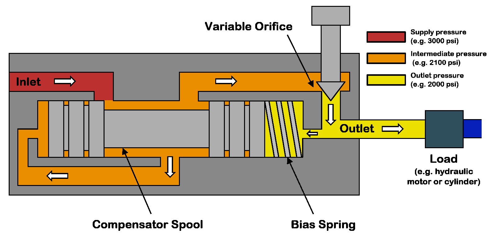
A pressure compensator works by comparing two pressure signals, one of which is a target and the other a pilot reading of downstream pressure. I’ve created a diagram showing a cutaway of a pressure compensated flow control and a symbol for the same (note, these valves are not identical). The primary difference between the two examples is the location of the compensator. The cutaway places the compensation before the variable orifice, while the symbol example places the compensator afterthe orifice. However, both will work so long as the compensator measures the pressure drop across the orifice.
Because flow rate is a function of pressure drop, and because pressure differential changes with flow rate, these understandings allow us to make sense of pressure compensator operation. Starting with the pressure compensated flow control symbol on the right, the flow path starts at port 1 and continues past port 3 out to the subcircuit being regulated.
The compensator has a spring value of 90 psi, and just like this example, most often, the spring value comes fixed. The compensator spool uses two pilot passages to measure pressure drop across the needle valve. In this case, port b measures pressure upstream of the needle valve at port 1, while port a measures downstream pressure at port 2.
The compensator spool will open or close itself to maintain 90 psi of differential pressure across the needle valve. Should load-induced pressure increase at port 2, the yellow pilot path to port a will push the spool backwards to open the combined flow path from port 1 to port 3. Should downstream pressure again decrease or supply pressure upstream of port 1 increase, any differential pressure than 90 psi will push the valve closed to restrict flow.
The cutaway example works much the same way. The red inlet flow must first pass a metering notch before entering the orange chamber, where the flow accesses its input. Next, metered flow crosses from orange to yellow before exiting the valve at the top. The yellowpassage comprises the differential pressure to the tune of the spring (assume 90 psi once again) trapped by the magenta spool. The difference in pressure between the orange and yellow defines the pressure drop through the needle valve.
Should downstream load-induced pressure at yellow start to decrease pressure drop from orange to yellow, the magenta spool moves backwards to open the flow path from red to orange, thereby increasing flow to sustain 90 psi pressure drop. Conversely, should pump-side pressure increase upstream of red, the increased pressure in the orange chamber will close the magenta spool against the spring. With less flow entering the orange chamber, pressure drop from orange to yellow remains stable at 90 psi.
In many ways, a pressure compensator is both a pressure and flow valve, but really quite simple in operation. For more information on pressure compensators, watch the Lunchbox Session videos on the subject. Expertly narrated by Carl Dyke, the first in the series can be found here.

Pressure compensation is the control of flow by compensating for the changes in load pressure. Most hydraulic systems today use pre-compensation as a means of maintaining consistent flow from an orifice or spool. However, there are applications when post-compensation has advantages over pre-compensation.
The fundamental difference is that with pre-compensation, the pressure drop across the orifice or spools is determined by the compensator. With post-compensation, the pressure drop is determined by the load sense (LS) spring inside the pump.
In post-compensated systems with multiple functions, the pump flow is divided at a fixed ratio. If flow settings exceed the pump output capability, the flow is reduced to each function at a fixed ratio. This is why post-compensation is sometimes referred to as “flow sharing”.
In post-compensated circuits, the pressure drop across each valve is determined by the load sense spring in the pump and all valves or orifices will have the same pressure drop. The load sense differential, sometimes referred to as standby, decreases when the pump cannot satisfy the total demand. All pressure compensators reference the highest load of the various functions.
The benefits include high efficiency under partial load and/or partial speed conditions and all functions slow down together at a fixed ratio when the pump cannot fully satisfy demand.
In the example below, the pump differential, or standby, is 200 PSI. The load sense pump will develop enough pressure to overcome the load and maintain a 200 PSI differential. The pressure drop across the valve or orifice remains fixed and is calculated by: system pressure minus the highest load pressure minus the compensator spring value.
The circuit below is an example of the flow sharing aspect. When another function is operated and the pump cannot fully satisfy the flow demand, the differential decreases. The pressure drop across each valve or orifice is reduced at the same fixed ratio, so the flow is divided, or shared, equally. In this example, each valve is fully open so total pump flow is shared equally between the functions.
So what happens when the functions require different flows and the pump cannot fully satisfy the total flow demand? The pump flow will be divided into the ratio of each function to total flow available. In the example below, the theoretical total flow demand is 42 GPM. The ratio of the function flow demand to total theoretical flow demand multiplied by the maximum pump flow is the resulting actual flow from each valve.
Post-compensation will increase stability and control in systems where demand can exceed the pump’s flow output. Because of its increased efficiency under partial load conditions, the compensator saves horsepower and reduces heat. It will also make the initial movement of actuators more predictable and provide better operator control.

On a recent project, there was a 25 horsepower motor running a torque limited piston pump. When we were doing performance testing, everything worked out fine. As soon as I left, the customer was complaining about excessive heat generation leading to downtime waiting for the oil to cool.
At first, I thought that a relief valve may be set below the compensator pressure, but a quick check showed they were operating correctly. So I did some research.
The problem wasn’t clear until I talked with the pump manufacturer. In order to keep a pressure compensated pump cool, the oil needs to be circulated internally. Depending on the manufacturer, 1/4 of the flow may be dumped back to tank to keep the pump cool.
Pressure compensated hydraulic systems tend to overheat because oil is continually circulated to keep the pump cool. The higher the standby pressure, the more heat created. Adding heat exchangers, shutting the pump down and lowering or having adjustable stand by pressure can reduce the heat generated.
So you have spent the extra money to get a piston pump, but do you know that there is a hidden danger in built in to these pumps? Let’s explore the danger
It turns out that pressure compensated systems are always moving oil, even when in standby. I found out that roughly 3 to 4 gpm were being dumped back to tank through the pump’s case drain at the compensator pressure. This was nearly 7 horsepower that was wasted.
This situation was not detected in testing, because we ran back to back tests with no idle time in between. Once the idle time was added in, we discovered that the oil temperature rose around 1-2 degrees per minute. An impressive feat on 100 gallons of hydraulic oil.
Adding a heat exchanger is a very obvious solution. These are usually forced air radiators made for hydraulics that are installed on the return line or the case drain line.
But as an engineer you should be asking yourself, “Why am I generating all this power just to heat the shop? That extra heat is going to make working in the summer excruciating.” All that an it is wasteful as well.
If we assume that we have 7 hp of wasted power from our pump during idle time, that is 5.2 kWh of energy. At 12 cents per kWh, that is $0.63 / hr of idle time.
If the only reason you are adding a heat exchanger is to reject idle time heat generation, there are many other options which we will explore below. Don’t let the simplicity of the a heat exchanger solution be where you stop. Keep reading.
As an engineer, the first step should always be fully diagnosing the root cause and not just masking the symptom. If you notice excessive idle time, make inquiries as to why the machine idles so much. Is an operator waiting on another process? Is it breaktime? They are many reasons for high idle time.
If the idle time can be modified by a process change or other external change, do that. However, don’t let that be your only change. People and processes aren’t perfect so expect those types of changes to occasionally fail.
This one is pretty self explanatory. If the system doesn’t need to be on, shut it down. If the system isn’t running, it can’t create heat. In fact, it has the opportunity to reject heat out of the system. Win-win!
Luckily, pressure compensated systems will start in a loaded condition. There should be no (or little) pressure on the outlet and compensator. This means that when starting the motor, it won’t be anywhere near fully loaded. Since there is no pressure, it will take 1-3 seconds for the pump to produce enough pressure to load up the compensator. This will usually be long enough to minimize startup loads on the motor.
If the machine is PLC controlled, adding a timer is easy to do when the machine is idle. This will be a good back up to the case where an operator accidentally leaves the system on when it is break time.
In the machine discussed above, we added a 2 minute timer for periods when there were no outputs given to any function. This was a great protection from heat generation, plus it was a signal to the operator that he or she was taking too long. Yes, it also had the side effect of increased production.
If excessive motor startup is a real concern, you may want to add a restart delay. This is common in HVAC systems where it is common to see a 5 minute ‘compressor delay’. This delay probably adds many hours of life to your HVAC system.
In some hydraulic systems, you just don’t need the system pressure you designed for. As a good designer, you have calculated your pressures and flows for less than what is available. As a result, you can reduce the standby pressure, but only minimally.
I say minimally, because there isn’t a drastic reduction in power with this one. However, you know your machine better than I do, so maybe there is more energy savings here.
This option is the most expensive and most efficient. By using an electro-proportional relief valve (DO3 P to T relief valve for industrial applications), you can set the compensator pressure for exactly what you need for the current function. As the functions change, the compensator pressure changes.
This is the most expensive option because your PLC system is going to have to output an analog signal (usually 0 – 10VDC) to control the electro-proportional relief valve (also expensive). As a good designer, you will also want a pressure sensor to provide feedback on the system.
However, this system is fully customizable and can act similiar to a load sensing mobile system. Through careful programming, you can tailor your pressure setting to what that function needs at any particular time.
Be cautious, the programming can get very complicated. It may not seem to be a big deal now, but will cause headaches in years to come when you or others will need to service the machine.
This is a much simpler version of the adjustable compensator option above. In this scenario, we would have one or more compensator relief valves switched on or off by non-proportional solenoid valves.
In this system, there would be one relief valve (main relief below) tied directly to the compensator and other relief valves are separated from the pressure line by 2 position, 2 way, normally closed solenoid operated valve. The main valve must be set at the maximum desired pressure so that if all else fails, the system will have a direct path of pressure control. The other valves can be activated, one at a time, to control the pressure for certain pressures.
This system cost is also reduced from the adjustable relief valve option because it eliminates the needed analog control system and extra programming for the PLC.
Additionally, the system can be made to look quite neat as well. Having a multisection DO3 manifold with the pressure port connected to the compensator will provide the foundation. Often, you can get the main relief valve already incorporated into the manifold which is a big bonus. You can then add solenoid valves on as the first row. On top of those valves you can add the individual relief valves.
If none of the sections are energized, the pump will create the maximum pressure which is set in the manifold relief valve. If one or more sections are activated, the pump will create pressure to the lowest set active pressure. In the schematic above, you can adjust the compensator pressure to 600 psi, 1200 psi, 2200 psi or 2750 psi depending on which sections are activated.
This can be a subset of several other options. If your system idles for long periods of time, you can just have a 2 position, 2 way, normally closed solenoid valve dump the pressure to tank. This will destroke the pump and not create any heat.
Another option on this is to couple it with a timer so that if there is no demand for the system hydraulics, the solenoid will activate and the pressure will be reduced. When demand for higher pressures is needed, the PLC will deactivate this solenoid.
I actually chose two of these solutions. First, I put a two minute timer on when the system is in normal standby. There is also a 25 minute timer when the system is in the cutting mode. At the 25 minute cycle, only 500 psi is needed to operate a hydraulic motor and control the travel of a saw.
In cutting mode, I also reduced the standby pressure from 2750 psi to 500 psi reducing the needed power by 82%. Sweet! I accomplished this by adding a second compensator relief valve that is activated by a 2 position 3 way valve.
Pressure compensated systems are generally more efficient and with a torque limiter they will give you the best performance of any other hydraulic system. Unfortunately, they do have the drawback of heat generation when in standby mode. If the solutions above are applied, you can often eliminate the need for a heat exchanger.

Why would we want to add this extra complication to our hydraulic systems?Having a hydraulic pump which reduces its output to near zero when the system pressure reaches maximum saves the system from pointlessly forcing oil over a relief valve.
Whenever a system is at maximum pressure, and the pump is a fixed displacement model, like a gear pump, then the system is at maximum displacement as well.
The combination of these two maximums also means that the power requirement from the prime mover (diesel engine or electric motor) is at maximum as well.A prime mover at maximum power is consuming maximum energy (fuel or electricity). Much of this energy is being used for nothing other than a conversion to heat.
You could compare this to operating a truck at maximum throttle while it is parked against a solid wall of rock. You"ll burn a lot of fuel but you won"t be doing any useful work!

www.powermotiontech.com is using a security service for protection against online attacks. An action has triggered the service and blocked your request.
Please try again in a few minutes. If the issue persist, please contact the site owner for further assistance. Reference ID IP Address Date and Time 8bf2006c85a66667641f5dd58dcb3d35 63.210.148.230 03/12/2023 08:49 AM UTC

Variable Plunger Pump How To Work#Hydraulic System (6.11 MB) ~ Free Download Variable Plunger Pump How To Work#Hydraulic System (04:27 Min) mp3 and mp4 ~ Download lagu mp3 & mp4 Variable Plunger Pump How To Work#Hydraulic System for free, fast and easy on MP3 Music Download.

When servicing and troubleshooting hydraulic equipment, we all make mistakes. After all, we are human. These mistakes can cost us in many ways and almost always result from a lack of competent training. Working around hydraulic machines can be a complex exercise, as it involves a great deal of science. To avoid these common mistakes, a logical approach based on knowledge (including knowing the function of each hydraulic component) and sound troubleshooting principles is required.
Hydraulic systems operate at high pressures and flow rates. As a result, they have the inherent ability to burn, maim or kill. In addition, leakage of hydraulic oil can lead to slips and falls. However, knowing these facts as well as the function of each hydraulic component are only the “tip of the iceberg” when preventing accidents.
When working around hydraulic systems, the proper PPE (Personal Protection Equipment) must be worn. At a minimum, safety glasses or “full face” protection must be worn. Long sleeves and gloves should be worn to protect from burns and cuts. In addition, steel- or composite-toed safety shoes should be worn especially when replacing heavy components such as pumps and cylinders.
Since a great deal of energy is contained in a hydraulic system, most facilities will have LOTO (Lock Out / Tag Out) procedures to be followed prior to servicing the equipment. The goal of these LOTO procedures is to put the system in a “zero-energy state” to prevent the sudden release of energy. However, I know of many cases where these procedures were followed to the letter and personnel were still injured or killed while servicing a machine.
This is because of a lack of knowledge on the part of many people who write the LOTO procedures. They believe that their procedures are putting the machine in a zero-energy state, when there may in fact still be energy stored in the system. This is especially true wherever accumulators are used. Most systems will contain an automatic and/or manual dump valve (usually located in a block at the base of the accumulator) which will allow the pressurized oil in the accumulator to bleed to the reservoir when the system is turned off. If the automatic dump valve fails closed or the manual dump valve is not opened, pressurized oil will be maintained in the accumulator. If a line or component is removed, then someone may suffer an injection injury. Initially, an injection injury may seem minor. However, this is very serious as most hydraulic fluids are extremely toxic and any delay in proper medical treatment can lead to amputations or death.
One common mistake is to assume that if a pressure gauge reads zero pressure, then it is safe to remove lines and components. However, most systems will have a check valve for pump isolation, and the gauge is installed on the pump side of this check valve instead of the accumulator side. When the pump is turned off, the oil will bleed to the reservoir through the internal clearances in the pump. The technician will then think that the pressure is zero and will have no way of knowing if the pressurized oil in the accumulator has been released. On any system using this type of check valve, a gauge should be installed at or near the accumulator and a manual accumulator dump valve should be installed. Opening the dump valve should then become part of the LOTO procedures. This is the only way to be sure that all the energy has been released.
As I spend time with plant personnel, I find that many people do not understand the difference between pressure and flow. Some even believe that pressure and flow are the same thing! This is why it is a common misconception that pressure must be increased to increase actuator speed. While it is true that pressure will increase actuator speed when standard (non-pressure compensating) flow controls are used, it is important to understand why this occurs.
One of the factors affecting the flow through a flow control is the difference between the inlet and outlet pressures. The pressure downstream of a flow control will be determined by the pressure required to move the load. This pressure will remain fairly constant, so long as the weight of the load does not change. The pressure at the flow control inlet will be at or near the pump compensator setting (when using a pressure compensating pump), so long as the pump can deliver sufficient volume. The difference between these two pressures is known as the pressure drop. Assuming the oil temperature and viscosity remain constant, an increase in pressure drop will result in increased flow through the flow control. This will in turn cause an increase in the actuator speed. The problem with this method is that the pressure has been increased well above the pressure required to do the work required. This only leads to shock and decreased component and hose life. It is also impossible to change the speed in one actuator without affecting the speed of the other actuators when using this method. When the speed of an actuator needs to be changed, it should only be done by adjusting the flow controls in the specific circuit. Just remember that the rate of oil flow controls speed, not pressure!
Another misconception pertains to the function of a hydraulic pump. I have found that about 60 to 70% of people believe that a pump makes pressure. This is understandable, as some so-called “hydraulic instructors” are teaching this to their students. In addition, a pressure compensated pump has an adjustment (compensator) that will change the pressure at the outlet of the pump, which adds to the confusion. However, this is simply NOT the case! The function of a hydraulic pump is to produce flow. As this flow produced by the pump encounters resistance, pressure will build. If you were to direct the pump volume directly to the reservoir, no appreciable pressure would be generated (as long as there is no resistance to the flow). It is important to remember that we must have two things to build pressure in a hydraulic system: flow (which the pump produces) and resistance (which is produced by the load). In the case of a pressure compensated pump, the pump will de-stroke to near zero volume when no flow is required.
When a machine failure occurs, many technicians will simply start changing parts until the machine starts working again. I discovered this in my 25+ years in repairing hydraulic components. I found that approximately 80% of the components I received for repair had absolutely nothing wrong with them! In our hydraulic troubleshooting workshops, we stress five elements necessary for troubleshooting and maintaining hydraulic systems:
This is the first tool that should be used when troubleshooting a hydraulic issue. It is nearly impossible to determine the cause of an issue if one does not fully understand how all the components are interconnected.
With a few exceptions, a hydraulic component can be tested without removing it from the system. This is facilitated by an understanding of the function and internal operation of various components.
It is very important to understand how to properly adjust the various components on the system. Having an improperly adjusted component is equivalent to having the wrong component installed.
Knowing the proper reliability checks to make can significantly reduce machine failures. These include temperature, pressure and speed checks. Of course, these checks should be made when the machine is operating normally to establish a baseline reference for future troubleshooting.
When a machine is not operating properly, there is usually only one component that has failed. Once that component is isolated, a replacement is sometimes selected simply because it looks the same and fits on the machine. However, pumps and valves can have many internal differences which can affect their operational characteristics. The model codes should be carefully compared, as each number or letter indicates a particular feature of the component. If there are any differences, then the manufacturer’s documentation should be consulted to determine what that difference is. On several occasions, I have traveled several hours to troubleshoot an issue only to find that the maintenance personnel had installed the wrong component.
When replacing a hydraulically piloted directional valve, careful consideration should be made as to the piloting configuration. These valves will have two additional ports in addition to the familiar “P”, “T”, “A” and “B” ports. One port will be marked “X” (pilot pressure) and the other will be marked “Y” (pilot drain). In an externally piloted and drained valve, the oil to and from the pilot valve is directed through these ports. If the valve is configured in this way and there is no pilot pressure at port “X”, the main spool of the valve will not shift and the actuator will not move. Many valve manufacturers use plugs inside the main body to change the piloting configuration. The manufacturer’s documentation will usually provide instructions for changing the configuration to the specific machine requirements.
Most maintenance personnel do an excellent job at changing pressure and return filters at specified intervals. However, the reservoir is usually not given any attention. Reservoirs are normally sized according to the total pump volume, but the reservoir size is also factored in to determine how much heat is removed from the system during operation. The outside of the reservoir should be cleaned regularly to ensure that a portion of the heat in the oil is transferred to the atmosphere through thermal transfer.
One filter that is often overlooked during maintenance is the breather filter. Many see the breather filter as no more than a “cap” that can be removed for adding oil to the system. However, it is a filter and should be serviced as such. As the system operates and cylinders extend and retract, the oil level in the reservoir will rise and drop. As the oil level rises, air is ported from the reservoir to the atmosphere through the breather filter. Likewise, atmospheric air is drawn into the reservoir as the oil level drops. The breather filter prevents airborne contaminants in the air from entering the reservoir when this occurs. I recently did a reliability assessment on a loading system at a paper mill. I noticed that the breather filter was severely deteriorated and looked as if it had not been changed in quite a while. None of the maintenance personnel could tell me if or when the breather filter had been changed. Considering its condition, it is likely that the breather filter had been in place since the system was installed 34 years prior!
Many systems use suction strainers to prevent large particles from entering the pumps. These strainers are often located inside the reservoir, so they tend to go without service. However, if these strainers become contaminated, the vacuum at the pump suction will increase and cause cavitation of the pumps. This cavitation will lead to pump damage. Some time ago, I received a call from a customer in Ontario, Canada regarding a pump that had been replaced several times. Each pump was very noisy, and they were perplexed as to why the noise remained even after they changed the pump. Of course, I immediately suspected cavitation, so I asked them to drain the tank and inspect the suction strainer. They found the suction strainer (pictured at right) had become contaminated and was causing cavitation of the pump. The strainer was cleaned and their problem was solved. Of course, inspection and servicing of the suction strainers is now a part of their regular preventative maintenance procedures!
Approximately 95% of hydraulic component failures are a result of contamination. One of the ways contamination can enter a hydraulic system is through adding unfiltered new oil. When hydraulic oil is first refined, it is relatively clean. However, once the oil is transferred to containers and transported, it can and will become contaminated. Several years ago, I received a call from a customer concerning a servo valve which I had repaired 8 years prior. He informed me that the valve had been in service all this time but had recently become very “sluggish” and eventually stopped working altogether. He advised that he was sending the valve in for repair, but that it was “no hurry” since he had a new valve that he had just installed and the system was again operational. Two days later, I received the failed valve for repair. I proceeded with an evaluation of the valve and found that the internal pilot filter was totally plugged with contaminants. I initially thought nothing of this since the valve had been in service for 8 years. However, I received yet another call from the customer advising that the new valve had failed after only three days! I asked if he had recently performed any maintenance on the system. He advised that they had recently serviced and cleaned the inside of the reservoir and had refilled the reservoir with new oil. When I asked him if the new oil had been filtered, he told me that it was new oil so it did not need to be filtered. This is a very common misconception and he was surprised to learn that he had inadvertently contaminated his system by refilling the reservoir with unfiltered new oil. In effect, he was effectively straining the contaminants in the oil through his servo valves.
Many systems incorporate a fill port for refilling the reservoir so that the new oil is ported through a filter. Standalone filter carts are also available for refilling the reservoir. Either way, any new oil added to the reservoir should be filtered. This is especially important on systems utilizing pressure compensated pumps and servo / proportional valves.
Although hydraulic machines have many advantages over other means of performing work, they are not immune to failures and downtime. The key to keeping them running is knowledge. In addition, most accidents can be prevented by a proper understanding of the fundamentals and science involved in hydraulic system operation.
Piston pumps are durable and relatively simple devices. A basic piston pump is made up of a piston, a chamber, and two valves. The pump operates by driving the piston down into the chamber, thereby compressing the media inside. In a hand pump, this is usually air. Once the pressure of the air exceeds that of the outlet valve spring, the compressed media goes through the open outlet valve. When the piston is drawn back up, it opens the inlet valve and closes the outlet valve, thereby utilizing suction to draw in new media for compression.
Although somewhat expensive, piston pumps are among the most efficient types of pumps. They have an excellent pressure rating (as high as 10,000 psi), but their design makes them susceptible to contaminants. They provide an excellent solution for many high-pressure hydraulic oil pumping applications.
Axial piston pumps are positive displacement pumps that use multiple cylinders grouped around a central axis. The group of cylinders, usually containing an odd number, is called a cylinder block. The pistons within each cylinder are attached to a swashplate. The swashplate is also known as a cam or wobble plate and attaches to a rotating shaft. As the shaft turns, the angle of the swashplate changes, which drives the pistons in and out of their respective cylinders.
Since the swashplate is at an angle to the axis of rotation, the pistons must reciprocate axially as they orbit around the cylinder block axis. The axial motion of the pistons is sinusoidal. As a piston rises, it moves toward the valve plate. At this point in the rotation, the fluid trapped between the buried end of the piston and the valve plate is expelled to the pump"s discharge port through one of the valve plate"s semi-circular ports. As the piston moves back toward the valve plate, the fluid is pushed through the discharge port of the valve plate.
Axial piston pumps can be designed as variable displacement piston pumps, making them very useful for controlling the speeds of hydraulic motors and cylinders. In this design, a swashplate is used to vary the depth to which each piston extends into its cylinder as the pump rotates, affecting the volume of discharge. A pressure compensator piston is used in some designs to maintain a constant discharge pressure under varying loads. Cheaper pressure washers sometimes use fixed-rate designs.
In a typical pressure-compensated pump, the swashplate angle adjusts through the action of a valve using pressure feedback to make sure that the pump output flow is precisely enough to maintain a designated pressure. If the load flow increases, the pressure momentarily decreases, but the pressure-compensation valve senses the decrease and then increases the swashplate angle to increase the pump’s output flow, restoring the desired pressure.
Axial piston pumps can contain most of the necessary circuit controls intrinsically by controlling the swash-plate angle, to regulate flow and pressure. They are very reliable and can allow the rest of the hydraulic system to which they’re attached to be very simple and inexpensive.
They are used to power the hydraulic systems of jet aircrafts, being gear-driven off of the turbine engine"s main shaft, and are often used for automotive air conditioning compressors for cabin cooling. The design of these pumps meets the limited weight and space requirement in the vehicle"s engine bay and reduces vibrations.
Pressure washers also use these pumps, and axial reciprocating motors are used to power many machines. They operate on the same principles as axial piston pumps, except that the circulating fluid is provided under substantial pressure and the piston housing rotates and provides shaft power to another machine. A typical use of an axial reciprocating motor is powering small earthmoving machines such as skid loader machines.
This guide provides a basic understanding of axial piston pumps. To find out more about other types of pumps, read our guide here. For more information on related products, consult our other product guides or visit the Thomas Supplier Discovery Platform to locate potential sources or view details on specific products.

The known benefit is that a pressure compensated variable displacement pump operates at a low standby pressure when no functions are active. When a function operates that requires less than full flow and pressure, the pump produces only the required flow at a pressure slightly higher than the actual load pressure. Typical hydraulic courses have graphs showing the power savings when compared to a fixed displacement pump or a variable displacement pressure compensated pump operating at compensator pressure when the theoretical output load pressure and flow requirement is less than the pump capacity. These examples only show the potential energy savings when one pump controls one actuator. When one pump supplies multiple actuators operating at different pressure and flow requirements, any potential energy savings rarely matches the optimum value provided by the classroom example. Interconnecting multiple pumps to work together can also be challenging.
Load sense has become so widely accepted that many manufacturers have valves designed specifically for load sense applications. The valves have a series of internal shuttle valves to send the highest load pressure requirement to the load sense output port. The typical valve also has ports to “daisy chain” load sense signals from other valves, so the highest load pressure requirement supplies the load sense port on the pump. The valve at the end of the daisy chain bleeds off the load sense pressure when no valve is actuated.
There are several drawbacks to load sense control that make applying it challenging in some applications. The main issues relate to the load sense feedback line itself. You typically use a 1/4-inch (6-mm) or 3/8-inch (10-mm) diameter hose. In cold environments, the oil in the line can be highly viscous and fail to produce an adequate signal to pump. Also, on large machines with multiple valve locations over long distances, the time delay for the pressure signal to reach the pump load sense port results in sluggish reaction. If the load pressure changes increase and decrease too quickly, the pump overcompensates and causes instability. A common solution is to add a bleed orifice at the pump for a small continuous flow that keeps the fluid warm and less viscous. The orifice also helps dampen pressure spikes, allowing the pump to respond in a more stable manner. This bleed orifice can require an increase to the load sense line to accommodate the associated pressure drop. Occasionally flow controls with a bypass check are added to the load sense circuit to stabilize the system. In extreme cases, accumulators are also utilized.
As electrohydraulic proportional directional control valves with related digital controllers become more popular, the possibility of using electronic load sensing also becomes more practical and offers other advantages. While you can use electronic load sensing with manually operated valves, it may not offer some of the additional benefits.
Electronic load sense control is accomplished by replacing the load sense feedback line with pressure transducers at each valve. Instead of daisy chaining multiple valves together, each valve can have its own dedicated transducer. Each transducer sends a signal to an electronic control module. The pump control changes from a load sense control, which requires a pressure signal to the load sense port, to a remote pressure control that sends a pressure signal to a remote relief valve. The remote relief valve then adjusts the compensator pressure to match the load pressure up to the main pump compensator setting. The proportional pilot relief is controlled by the same electronic controller that is receiving the signal from the multiple pressure transducers. Simple systems with minimal outputs or manually operated valves may only require one controller for the entire machine. For complex systems requiring multiple transducer inputs, multiple proportional directional valves, and more than one pump control output, it may be more practical to use a dedicated controller for the load sense functions. The program evaluates the pressure transducer inputs, then outputs the highest pressure command to the pump pilot pressure control. Many remote proportional controls on the pump still have some form of a differential spring; or you can add a differential pressure to the control signal.
The first benefit of electronic load sense is the almost instant response of a pressure signal. Cold viscous oil, excessive line lengths, or the capacitance of the pilot line do not affect the signal.
Electronic load sensing can provide variable differential settings. The common load sense control on the pump has a fixed differential or standby pressure setting. It can be tuned during commissioning, but it is typically not adjusted after that. The nominal pressure can vary from 15 to 35 bar (220 to 500 psi) depending on the pump and valve requirements. When a bleed orifice is installed, the flow-pressure drop also affects the differential setting and pump response. The electronic load sense control responds not only to the pressure signal, it also provides a differential pressure that responds to the valves being commanded. In one application, a feed cylinder had to be limited in the retract force. In this case the cylinder was the only function active for that part of the cycle. Limiting the pilot pressure when that specific function was actuated to retract the cylinder limits the retract force. An added benefit was that the load sense pressure was also mapped to the retract command. A slight command increases the pump pressure setting slightly; the higher the operator command, the more the proportional directional valve opened and the pump pilot pressure increased. This resulted in a unique feathering ability to retract the cylinder.
Another benefit is the ability to ramp or delay the load sense pressure command at the pump. One application has a high standby pressure, nominally 35 bar (500 psi). When a function actuates, the differential pressure gradually lowers to 15 bar (200 psi) over the load pressure. The result is fast response when the valve shifts, followed by reduced pressure drop across the valve when the function is operating and the flow is higher.
Fan applications using load sense pressure compensated pumps often result in oscillation that requires considerable tuning. The challenge is that the oscillation is related to the pressure spiking when accelerating the fan, then dropping because the pump compensates at the same time the fan motor begins turning, and the fan inertia keeps the motor spinning. This oscillation can be alleviated by ramping the control pressure up relative to the commanded fan speed instead of the pressure. Since fans have a characteristic speed-torque curve, it can be programmed into the control without too much difficulty.
Because electronic load sensing uses a remote pressure control on the pump, a sophisticated control that calculates the flow requirements based on the summing proportional valve command values and the load pressures also provides a form of power limiting.
If an application requires a failure mode to ensure the functions can still operate, an inverse proportional relief can be used for the pilot control. The inverse proportional relief operates at full pressure with no command and reduces pressure as the command increases. The default condition causes the pump to operate as a simple pressure compensated pump if the load sense control program experiences a failure, such as a broken wire or other damage.
Electronic load sensing offers control options that in the past were either impractical or impossible. By combining the faster processing speeds of modern controllers with added I/O capacity, electronic load sense control optimizes the differential pressure of a conventional load sense system. Electronic controllers can now integrate system pressure with flow requirements to provide power-limiting features for a specific application.•

When you need to choose a hydraulic pump solution for a hydraulic system, it is important to decide what type of pump you will require. You must also understand the basics of how pumps work and hydraulics.
All hydraulic systems rely on pressurized fluid to create force in order to perform work that is accomplished by transforming mechanical energy into hydraulic energy inside hydraulic pumps and creating a positive displacement downstream. For example, a forklift needs to raise and lower pallets—which would be the desired work.
You must also choose between a ‘closed-loop’ or ‘open-loop’ system. In a ‘closed-loop’ system, the fluid passes from the pump directly to the motor before returning to the pump. In an ‘open-loop’ system, the pump draws the fluid from a reservoir or tank, and then pumps it to a control valve from where it is directed to the services being operated before returning to the tank.
Fixed-displacement pumps are well suited to a wide range of functions where the amount of pressure required to perform work is the same each and every time. For instance, if the pump is rated as a 30 cc pump, it will pump 30 ml of hydraulic fluid through the system for every single rotation.
The pressure and flow rate will not change, no matter how the pump is operated or what occurs elsewhere in the system. If you need a lower flow rate, then you will have to divert the excess flow or use a variable displacement pump.
Two common types of fixed-displacement pumps you can use are the bent axis piston pump and the gear pump. The bent axis piston pump provides the added benefit of normally having a higher pressure capability than a gear pump.
Aside from flow rates being directly proportional to pump drive speeds, fixed-displacement hydraulic pumps have several key benefits over variable displacement pumps, including:
Unlike fixed-displacement pumps, variable displacement pumps are able to increase or decrease the fluid flow rates electronically, manually, or hydraulically. The method used will depend on the flow required and the type of pump being used, such as a vane pump, axial piston pump, etc.
Furthermore, the method of displacement changes based on the pump’s internal structure. For example, a variable displacement piston pump is determined by the bore area of the pistons and the stroke length. The stroke length can vary to help regulate the flow rates as shaft rotation turns and moves the pistons inside the pump.
The control piston inside the pump also helps regular pressure and, essentially, functions as a relief valve. When pressure increases above the desired pressure compensator setting, the control piston moves outwards and slows the travel distance of the other pistons.
As can be seen, fixed-displacement pumps and variable displacement pumps have their own benefits, depending on your specific needs. For further assistance in choosing the right pump or for other hydraulic system solutions, please feel free to contact White House Products, Ltd. at +44 (0) 1475 742500 today!

Pressure compensation systems operate a little like feedback-based electronic systems. That’s not exactly a surprise, not when hydraulics circuits can become every bit as complex as any electronically based wiring. At any rate, the similarities are there for everyone to observe. When an output change occurs, a fraction of that change is sent back to govern the control unit, be it a preamplifier or a hydraulic actuator.
Sticking with fluid-based systems, as a load pressure varies, a fractional amount of that energy is dispatched back to the flow controlling mechanism to perform its pressure compensation duties. That’s how post-compensation hydraulics systems work. Of course, to realize this design, a load sensing pump or actuator must accept a feedback sensing line. For example, sticking with pump architectures for a moment, a piston pump would receive the feedback pressure. From here, the line would connect directly to the pump swash plate. As the equipment load varied, that signal would make the swash pate perform its pressure compensating assignment. Again, this is how post-compensation systems operate. Having become outmoded over time, pre-compensation technology has long since taken over.
Known also as “flow sharing,” post-compensation configurations have limitations. Basically, there are some disadvantages to having a fixed ratio pressure drop. Equipment responsiveness is also sometimes limited when controlled by load sensing lines and springs. Instead of the LS spring, pre-compensation devices adopt the following principle. With a different architecture, this pressure compensation circuit measures a load-generated pressure differential over individual valve spools or orifices. Sure, there’s less chance of a flow sharing issue when individual valve orifices are monitored in this way, but now each of those monitored valves is “blind” to the functions of its neighbours. No matter, when or if a system pump becomes load saturated, the pressure compensation mechanism will responsively access more pump power, perhaps by adjusting the pump swash plate, or perhaps by adjusting a pilot signal on some other hydraulic pump type.
There are two principal forms of pressure compensation. If a heavy load threatens to swamp the system pump, load sensing feedback lines and springs adjust pump performance. That’s how a post-compensation circuit operates. For pre-compensation systems, the compensator monitors pressure differentials across each valve orifice. Fortunately, new waves of advanced mobile hydraulics devices are now adding pressure compensation options, which include porting controls for pre or post-compensation controls. That leaves the designer free to weigh the pros and cons of both solutions. For one thing, does a designer really want to introduce flow sharing? If not, turn instead to pre-compensation configured load controls.


 8613371530291