
pressure compensated hydraulic pump how it works free sample

www.powermotiontech.com is using a security service for protection against online attacks. An action has triggered the service and blocked your request.
Please try again in a few minutes. If the issue persist, please contact the site owner for further assistance. Reference ID IP Address Date and Time 8bf2006c85a66667641f5dd58dcb3d35 63.210.148.230 03/12/2023 08:48 AM UTC

A pressure compensator is a device built into some pumps for the purpose of automatically reducing (or stopping) pump flow if system pressure sensed on the pump outlet port, should rise above a pre-set desired maximum pressure (sometimes called the "firing" pressure). The compensator prevents the pump from being overloaded if an overload is placed on the hydraulic system.
A compensator is built into the pump at the factory and usually cannot be added in the field. Any pump built with variable displacement can be controlled with a compensator. These include several types of axial piston pumps and unbalanced (single lobe) vane pumps. Radial piston pumps can sometimes be built with variable displacement but do not lend themselves readily to this action. Most other positive displacement pumps including internal and external gear, balanced (double lobe) vane, gerotor, and screw types cannot be built with variable displacement.
Figure 1 is a schematic of a check valve axial piston pump, variable displacement, controlled with a pressure compensator. The pistons, usually 5, 7, or 9 in number, are stroking inside a piston block which is keyed to and is rotating with the shaft. The left ends of the pistons are attached through swivel joints, to piston shoes which bear against and slide around on the swash plate as the piston block rotates. The swash plate itself does not rotate; it is mounted on a pair of trunnions so it can swivel from neutral (vertical) position to a maximum tilt angle. The angle which the swash plate makes to the vertical causes the pistons to stroke, the length of stroke being proportional to the angle. Normally, at low system pressures, the swash plate remains at its maximum angle, held there by spring force, hydraulic pressure, or by the dynamics of pump construction, and pump flow remains at maximum. The compensator acts by hydraulic pressure obtained internally from the pump outlet port. When pump pressure rises high enough to over-come the adjustable spring behind the compensator piston, the "firing" pressure has been reached, and the compensator piston starts to pull the swash plate back toward neutral, reducing pump displacement and output flow. The spring in the compensator can be adjusted for the desired maximum or "firing" pressure.
Under working conditions, on a moderate system overload, the compensator piston reduces the swash plate angle just enough to prevent the system pressure from exceeding the "firing" pressure adjusted on the compensator. On severe overloads the compensator may swing the swash plate back to neutral (vertical) to reduce pump flow to zero.
Maximum Displacement Stops. Some pumps are available with internal stops to limit the tilt angle of the swash plate. These stops limit the maximum flow and limit the HP consumption of the pump. They may be fixed stops, factory installed and inaccessible from the outside, or they may be externally adjustable with a wrench.
Manual Control Lever. Some pressure compensated pumps, especially hydrostatic transmission pumps, are provided with an external control lever to enable the operator to vary the swash plate angle (and flow) from zero to maximum. On these pumps the pressure compensator is arranged to override the manual lever and to automatically reduce the swash plate angle if a system overload should occur even though the operator control lever is still shifted to maximum displacement position.
Basically the pressure compensator is designed to unload the pump when system pressure reaches the maximum design pressure. When the pump is unloaded in this way, there is little HP consumed and little heat generated even though pressure remains at the maximum level, because there is no flow from the pump.
Variable displacement pumps are usually more expensive than fixed displacement types, but are especially useful in systems where several branch circuits are to be supplied from one pump, and where full pressure may be required simultaneously in more than one branch, and where the pump must be unloaded when none of the branches is ill operation. If individual 4-way valves are used in each branch, each valve must have a closed center spool. The inlet ports on all 4-way valves must be connected in parallel across the pump line. However, if all branch circuits are operated from a bank valve of the parallel type, a pressure compensated variable displacement pump may not be necessary; a fixed displacement pump, gear, vane, or piston, may serve equally well because the bank valve will unload the pump when all valve handles are placed in neutral, but when two or more handles are simultaneously shifted, their branch circuits will automatically be placed in a parallel connection.
As in all hydraulic systems, more pump oil will flow to the branch with the lightest load. Bank valve handles can be modulated to equalize the flow to each branch. When individual 4-way valves are used in each branch, flow control valves may be installed in the branch circuits and adjusted to give the flow desired in each branch.
Figure 2 shows a multiple branch circuit in which a variable displacement pump is used to advantage. Individual 4-way valves, solenoid operated, are used for each branch, and they have closed center porting. Please refer to Design Data Sheet 54 for possible drift problems on a pressure manifold system. A pressure relief valve is usually required even with a pressure compensated pump due to the time interval required for the swash plate to reduce its tilt angle when a sudden overload occurs. The relief valve will help absorb part of the pressure spike generated during this brief interval. It should be adjusted to crack at about 500 PSI higher than the pressure adjustment of the compensator piston spring to prevent oil discharge across it during normal operation.
All hydrostatic transmission systems use a variable displacement pump with pressure compensator, and often combine the compensator with other controls such as the horsepower input limiter, load sensing, flow sensing, or constant flow control.
© 1990 by Womack Machine Supply Co. This company assumes no liability for errors in data nor in safe and/or satisfactory operation of equipment designed from this information.
A hydraulic pump is a mechanical device that converts mechanical power into hydraulic energy. It generates flow with enough power to overcome pressure induced by the load.
A hydraulic pump performs two functions when it operates. Firstly, its mechanical action creates a vacuum at the pump inlet, subsequently allowing atmospheric pressure to force liquid from the reservoir and then pumping it through to the inlet line of the pump. Secondly, its mechanical action delivers this liquid to the pump outlet and forces it into the hydraulic system.
The three most common hydraulic pump designs are: vane pump, gear pump and radial piston pump. All are well suited to common hydraulic uses, however the piston design is recommended for higher pressures.
Most pumps used in hydraulic systems are positive-displacement pumps. This means that they displace (deliver) the same amount of liquid for each rotating cycle of the pumping element. The delivery per cycle remains almost constant, regardless of changes in pressure.
Positive-displacement pumps are grouped into fixed or variable displacement. A fixed displacement pump’s output remains constant during each pumping cycle and at a given pump speed. Altering the geometry of the displacement chamber changes the variable displacement pump’s output.
Fixed displacement pumps (or screw pumps) make little noise, so they are perfect for use in for example theatres and opera houses. Variable displacement pumps, on the other hand, are particularly well suited in circuits using hydraulic motors and where variable speeds or the ability to reverse is needed.
Applications commonly using a piston pump include: marine auxiliary power, machine tools, mobile and construction equipment, metal forming and oil field equipment.
As the name suggests, a piston pump operates through pistons that move back and forth in the cylinders connected to the hydraulic pump. A piston pump also has excellent sealing capabilities.
A hydraulic piston pump can operate at large volumetric levels thanks to low oil leakage. Some plungers require valves at the suction and pressure ports, whilst others require them with the input and output channels. Valves (and their sealing properties) at the end of the piston pumps will further enhance the performance at higher pressures.
The axial piston pump is possibly the most widely used variable displacement pump. It’s used in everything from heavy industrial to mobile applications. Different compensation techniques will continuously alter the pump’s fluid discharge per revolution. And moreover, also alter the system pressure based on load requirements, maximum pressure cut-off settings and ratio control. This implies significant power savings.
Two principles characterise the axial piston pump. Firstly the swash plate or bent axis design and secondly the system parameters. System parameters include the decision on whether or not the pump is used in an open or closed circuit.
The return line in a closed loop circuit is under constant pressure. This must be considered when designing an axial piston pump that is used in a closed loop circuit. It is also very important that a variable displacement volume pump is installed and operates alongside the axial piston pump in the systems. Axial piston pumps can interchange between a pump and a motor in some fixed displacement configurations.
The swivel angle determines the displacement volume of the bent axis pump. The pistons in the cylinder bore moves when the shaft rotates. The swash plate, in the swash plate design, sustain the turning pistons. Moreover, the angle of the swash plate decides the piston stroke.
The bent axis principle, fixed or adjustable displacement, exist in two different designs. The first design is the Thoma-principle with maximum 25 degrees angle, designed by the German engineer Hans Thoma and patented in 1935. The second design goes under the name Wahlmark-principle, named after Gunnar Axel Wahlmark (patent 1960). The latter features spherical-shaped pistons in one piece with the piston rod and piston rings. And moreover a maximum 40 degrees between the driveshaft centre-line and pistons.
In general, the largest displacements are approximately one litre per revolution. However if necessary, a two-litre swept volume pump can be built. Often variable-displacement pumps are used, so that the oil flow can be adjusted carefully. These pumps generally operate with a working pressure of up to 350–420 bars in continuous work
Radial piston pumps are used especially for high pressure and relatively small flows. Pressures of up to 650 bar are normal. The plungers are connected to a floating ring. A control lever moves the floating ring horizontally by a control lever and thus causes an eccentricity in the centre of rotation of the plungers. The amount of eccentricity is controlled to vary the discharge. Moreover, shifting the eccentricity to the opposite side seamlessly reverses the suction and discharge.
Radial piston pumps are the only pumps that work continuously under high pressure for long periods of time. Examples of applications include: presses, machines for processing plastic and machine tools.
A vane pump uses the back and forth movement of rectangle-shaped vanes inside slots to move fluids. They are sometimes also referred to as sliding vane pumps.
The simplest vane pump consists of a circular rotor, rotating inside of a larger circular cavity. The centres of the two circles are offset, causing eccentricity. Vanes slide into and out of the rotor and seal on all edges. This creates vane chambers that do the pumping work.
A vacuum is generated when the vanes travel further than the suction port of the pump. This is how the oil is drawn into the pumping chamber. The oil travels through the ports and is then forced out of the discharge port of the pump. Direction of the oil flow may alter, dependent on the rotation of the pump. This is the case for many rotary pumps.
Vane pumps operate most efficiently with low viscosity oils, such as water and petrol. Higher viscosity fluids on the other hand, may cause issues for the vane’s rotation, preventing them from moving easily in the slots.
Gear pumps are one of the most common types of pumps for hydraulic fluid power applications. Here at Hydraulics Online, we offer a wide range of high-powered hydraulic gear pumps suitable for industrial, commercial and domestic use. We provide a reliable pump model, whatever the specifications of your hydraulic system. And we furthermore ensure that it operates as efficiently as possible.
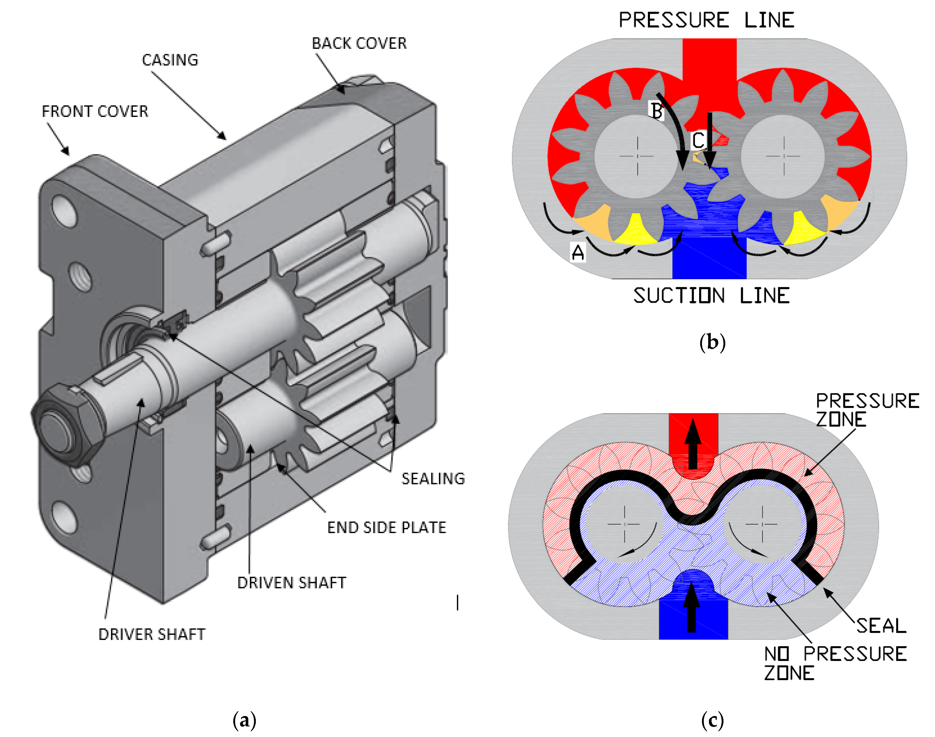
Johannes Kepler invented the gear pump around year 1600. Fluid carried between the teeth of two meshing gears produces the flow. The pump housing and side plates, also called wear or pressure plates, enclose the chambers, which are formed between adjacent gear teeth. The pump suction creates a partial vacuum. Thereafter fluid flows in to fill the space and is carried around the discharge of the gears. Next the fluid is forced out as the teeth mesh (at the discharge end).
Some gear pumps are quite noisy. However, modern designs incorporating split gears, helical gear teeth and higher precision/quality tooth profiles are much quieter. On top of this, they can mesh and un-mesh more smoothly. Subsequently this reduces pressure ripples and related detrimental problems.
Catastrophic breakdowns are easier to prevent with hydraulic gear pumps. This is because the gears gradually wear down the housing and/or main bushings. Therefore reducing the volumetric efficiency of the pump gradually until it is all but useless. This often happens long before wear causes the unit to seize or break down.
Can hydraulic gear pumps be reversed? Yes, most pumps can be reversed by taking the pump apart and flipping the center section. This is why most gear pumps are symmetrical.
External gear pumps use two external spur gears. Internal gear pumps use an external and an internal spur gear. Moreover, the spur gear teeth face inwards for internal gear pumps. Gear pumps are positive displacement (or fixed displacement). In other words, they pump a constant amount of fluid for each revolution. Some gear pumps are interchangeable and function both as a motor and a pump.
The petrochemical industry uses gear pumps to move: diesel oil, pitch, lube oil, crude oil and other fluids. The chemical industry also uses them for materials such as: plastics, acids, sodium silicate, mixed chemicals and other media. Finally, these pumps are also used to transport: ink, paint, resins and adhesives and in the food industry.
Mathematical calculations are key to any type of hydraulic motor or pump design, but are especially interesting in the gerotor design. The inner rotor has N teeth, where N > 2. The outer rotor must have N + 1 teeth (= one more tooth than the inner rotor) in order for the design to work.

If you’d like to access more information about an introduction to hydraulic pumps, we highly recommend that you visit LunchBox Sessions’ website and make use of the fabulous resources available there.
Some of the sessions are free; you don’t need to sign up. However, if you are serious about expanding your knowledge of hydraulic systems, we recommend you consider signing up for a subscription to the entire LunchBox Session service. This way, you get full access to all the interactive training materials, tests and simulations for just $29 per month. Students are entitled to a 60% discount off this price when they share their college or university ID.

Pressure compensation is the control of flow by compensating for the changes in load pressure. Most hydraulic systems today use pre-compensation as a means of maintaining consistent flow from an orifice or spool. However, there are applications when post-compensation has advantages over pre-compensation.
The fundamental difference is that with pre-compensation, the pressure drop across the orifice or spools is determined by the compensator. With post-compensation, the pressure drop is determined by the load sense (LS) spring inside the pump.
In post-compensated systems with multiple functions, the pump flow is divided at a fixed ratio. If flow settings exceed the pump output capability, the flow is reduced to each function at a fixed ratio. This is why post-compensation is sometimes referred to as “flow sharing”.
In post-compensated circuits, the pressure drop across each valve is determined by the load sense spring in the pump and all valves or orifices will have the same pressure drop. The load sense differential, sometimes referred to as standby, decreases when the pump cannot satisfy the total demand. All pressure compensators reference the highest load of the various functions.
The benefits include high efficiency under partial load and/or partial speed conditions and all functions slow down together at a fixed ratio when the pump cannot fully satisfy demand.
In the example below, the pump differential, or standby, is 200 PSI. The load sense pump will develop enough pressure to overcome the load and maintain a 200 PSI differential. The pressure drop across the valve or orifice remains fixed and is calculated by: system pressure minus the highest load pressure minus the compensator spring value.
The circuit below is an example of the flow sharing aspect. When another function is operated and the pump cannot fully satisfy the flow demand, the differential decreases. The pressure drop across each valve or orifice is reduced at the same fixed ratio, so the flow is divided, or shared, equally. In this example, each valve is fully open so total pump flow is shared equally between the functions.
So what happens when the functions require different flows and the pump cannot fully satisfy the total flow demand? The pump flow will be divided into the ratio of each function to total flow available. In the example below, the theoretical total flow demand is 42 GPM. The ratio of the function flow demand to total theoretical flow demand multiplied by the maximum pump flow is the resulting actual flow from each valve.
Post-compensation will increase stability and control in systems where demand can exceed the pump’s flow output. Because of its increased efficiency under partial load conditions, the compensator saves horsepower and reduces heat. It will also make the initial movement of actuators more predictable and provide better operator control.

To understand how the load-sensing pump and directional control valve function together in operation, consider a winch being driven through a manually actuated valve. The operator summons the winch by moving the spool in the directional valve 20% of its stroke. The winch drum turns at five rpm. For clarity, imagine that the directional valve is now a fixed orifice. Flow across an orifice decreases as the pressure drop across it decreases. As load on the winch increases, the load-induced pressure downstream of the orifice (directional valve) increases. This decreases the pressure drop across the orifice, which means flow across the orifice decreases and the winch slows down.
In a load sensing circuit the load-induced pressure downstream of the orifice (directional valve) is fed back to the pump via the load-signal gallery in the directional control valve. The load-sensing controller responds to the increase in load pressure by increasing pump displacement (flow) slightly so that pressure upstream of the orifice increases by a corresponding amount. This keeps the pressure drop across the orifice (directional valve) constant, which keeps flow constant and in this case, winch speed constant.
The value of the pressure drop or delta P maintained across the orifice (directional valve) is typically 10 to 30 Bar (145 to 435 PSI). When all spools are in the center position the load-signal port is vented to tank and the pump maintains "standby" pressure equal to or slightly higher than the load sensing controller"s delta P setting.
Because the pump always receives the load signal from the function operating at the highest pressure, high-end load sensing directional control valves feature a pressure compensator (not shown) at the pressure inlet to each section. The section pressure compensator works with the spool-selected orifice opening to maintain a constant flow, independent of the pressure variations caused by the operation of multiple functions at the same time. This is sometimes referred to as "sensitive load sensing".
A load sensing pump only produces the flow demanded by the actuators - this makes it energy efficient (fewer losses to heat) and as demonstrated in the above example, provides more precise control. Load-sensing control also provides constant flow independent of pump shaft speed variations. If pump drive speed decreases, the load-sensing controller will increase displacement (flow) to maintain the set delta P across the directional control valve (orifice), until maximum displacement is reached.
Load sensing pump controls usually incorporate a pressure limiting control, also referred to as a pressure cut-off or pressure compensator. The pressure compensator limits maximum operating pressure by reducing pump displacement to zero when the set pressure is reached.
?I get e-mails like this all the time. I never find time to read them. I decided to read Issue #30 and I couldn"t put it down. I"ll make time from now on.?
?I just love this newsletter. As a Hydraulics Instructor for Eaton, I make copies and distribute them to my students as I address various topics. Please keep "em coming.?

Pressure compensated pumps, pressure compensated flow controls or even just straight-up pressure compensators – these terms are thrown around constantly. But unless you’re a hydraulic specialist, you may not know what these are, let alone what they do. Of course, you’ve probably heard of systems analysts and cartographers too, but even thoseguys don’t know what they do.
The word pressureis self-explanatory, but just considering the meaning of compensategoes far to explain its use here. The dictionary says: reduce or counteract (something unwelcome or unpleasant) by exerting an opposite force or effect. Take that pressure!Your shenanigans are not welcome here! Okay, so we do want pressure and lots of it. But sometimes we don’t, and that’s where a compensator comes in.
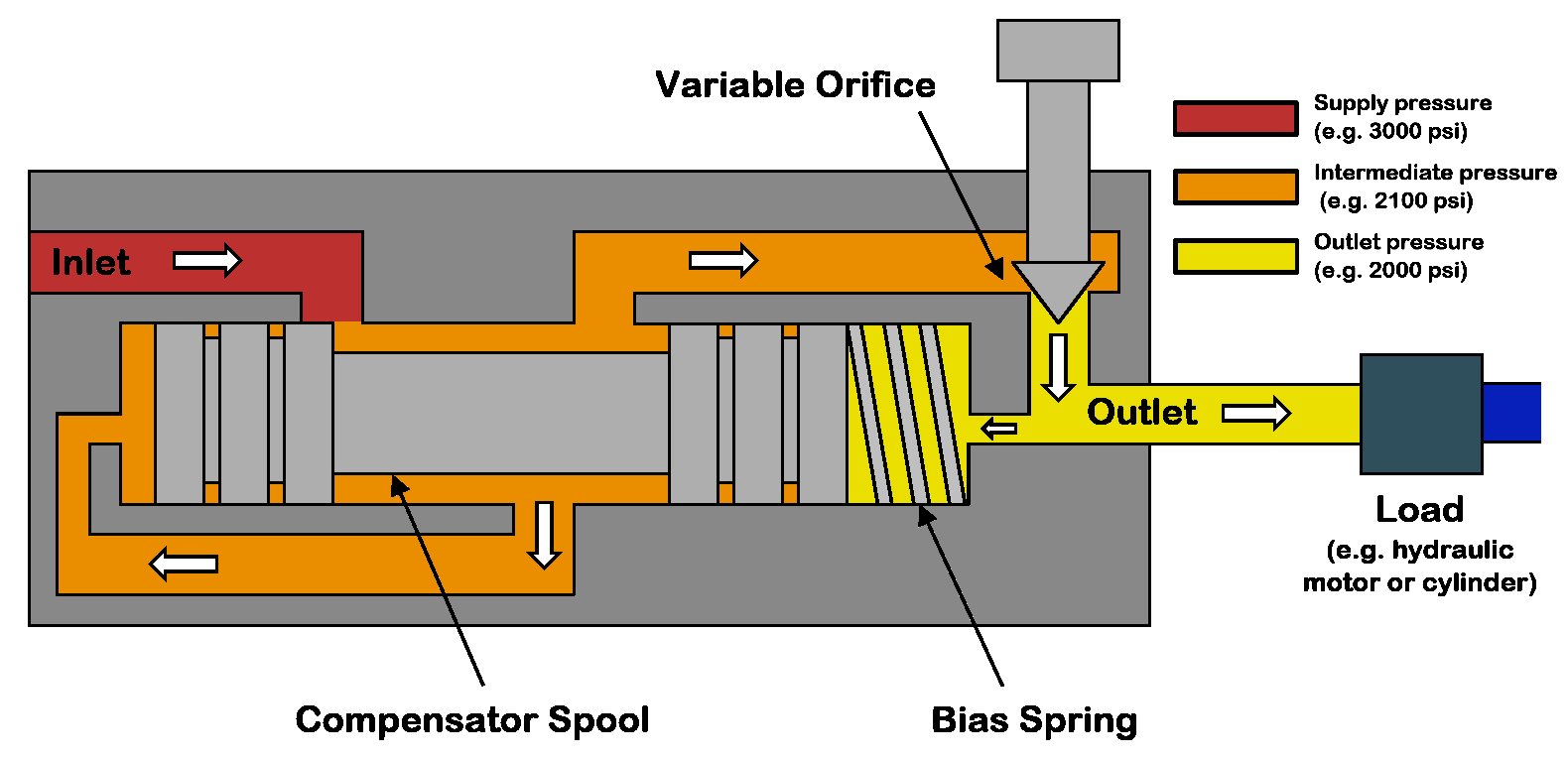
A pressure compensator works by comparing two pressure signals, one of which is a target and the other a pilot reading of downstream pressure. I’ve created a diagram showing a cutaway of a pressure compensated flow control and a symbol for the same (note, these valves are not identical). The primary difference between the two examples is the location of the compensator. The cutaway places the compensation before the variable orifice, while the symbol example places the compensator afterthe orifice. However, both will work so long as the compensator measures the pressure drop across the orifice.
Because flow rate is a function of pressure drop, and because pressure differential changes with flow rate, these understandings allow us to make sense of pressure compensator operation. Starting with the pressure compensated flow control symbol on the right, the flow path starts at port 1 and continues past port 3 out to the subcircuit being regulated.
The compensator has a spring value of 90 psi, and just like this example, most often, the spring value comes fixed. The compensator spool uses two pilot passages to measure pressure drop across the needle valve. In this case, port b measures pressure upstream of the needle valve at port 1, while port a measures downstream pressure at port 2.
The compensator spool will open or close itself to maintain 90 psi of differential pressure across the needle valve. Should load-induced pressure increase at port 2, the yellow pilot path to port a will push the spool backwards to open the combined flow path from port 1 to port 3. Should downstream pressure again decrease or supply pressure upstream of port 1 increase, any differential pressure than 90 psi will push the valve closed to restrict flow.
The cutaway example works much the same way. The red inlet flow must first pass a metering notch before entering the orange chamber, where the flow accesses its input. Next, metered flow crosses from orange to yellow before exiting the valve at the top. The yellowpassage comprises the differential pressure to the tune of the spring (assume 90 psi once again) trapped by the magenta spool. The difference in pressure between the orange and yellow defines the pressure drop through the needle valve.
Should downstream load-induced pressure at yellow start to decrease pressure drop from orange to yellow, the magenta spool moves backwards to open the flow path from red to orange, thereby increasing flow to sustain 90 psi pressure drop. Conversely, should pump-side pressure increase upstream of red, the increased pressure in the orange chamber will close the magenta spool against the spring. With less flow entering the orange chamber, pressure drop from orange to yellow remains stable at 90 psi.
In many ways, a pressure compensator is both a pressure and flow valve, but really quite simple in operation. For more information on pressure compensators, watch the Lunchbox Session videos on the subject. Expertly narrated by Carl Dyke, the first in the series can be found here.

When you need to choose a hydraulic pump solution for a hydraulic system, it is important to decide what type of pump you will require. You must also understand the basics of how pumps work and hydraulics.
All hydraulic systems rely on pressurized fluid to create force in order to perform work that is accomplished by transforming mechanical energy into hydraulic energy inside hydraulic pumps and creating a positive displacement downstream. For example, a forklift needs to raise and lower pallets—which would be the desired work.
You must also choose between a ‘closed-loop’ or ‘open-loop’ system. In a ‘closed-loop’ system, the fluid passes from the pump directly to the motor before returning to the pump. In an ‘open-loop’ system, the pump draws the fluid from a reservoir or tank, and then pumps it to a control valve from where it is directed to the services being operated before returning to the tank.
Fixed-displacement pumps are well suited to a wide range of functions where the amount of pressure required to perform work is the same each and every time. For instance, if the pump is rated as a 30 cc pump, it will pump 30 ml of hydraulic fluid through the system for every single rotation.
The pressure and flow rate will not change, no matter how the pump is operated or what occurs elsewhere in the system. If you need a lower flow rate, then you will have to divert the excess flow or use a variable displacement pump.
Two common types of fixed-displacement pumps you can use are the bent axis piston pump and the gear pump. The bent axis piston pump provides the added benefit of normally having a higher pressure capability than a gear pump.
Aside from flow rates being directly proportional to pump drive speeds, fixed-displacement hydraulic pumps have several key benefits over variable displacement pumps, including:
Unlike fixed-displacement pumps, variable displacement pumps are able to increase or decrease the fluid flow rates electronically, manually, or hydraulically. The method used will depend on the flow required and the type of pump being used, such as a vane pump, axial piston pump, etc.
Furthermore, the method of displacement changes based on the pump’s internal structure. For example, a variable displacement piston pump is determined by the bore area of the pistons and the stroke length. The stroke length can vary to help regulate the flow rates as shaft rotation turns and moves the pistons inside the pump.
The control piston inside the pump also helps regular pressure and, essentially, functions as a relief valve. When pressure increases above the desired pressure compensator setting, the control piston moves outwards and slows the travel distance of the other pistons.
As can be seen, fixed-displacement pumps and variable displacement pumps have their own benefits, depending on your specific needs. For further assistance in choosing the right pump or for other hydraulic system solutions, please feel free to contact White House Products, Ltd. at +44 (0) 1475 742500 today!

An axial piston pump is a positive displacement pump that has a number of pistons in a circular array within a hydraulic motor or an automotive air conditioning compressor.
An axial piston pump has a number of pistons (usually an odd number) arranged in a circular array within a housing which is commonly referred to as a cylinder block, barrel. This cylinder block is driven to rotate about its axis of symmetry by an integral shaft that is, more or less, aligned with the pumping pistons (usually parallel but not necessarily).
Mating surfaces. One end of the cylinder block is convex and wears against a mating surface on a stationary valve plate. The inlet and outlet fluid of the pump pass through different parts of the sliding interface between the cylinder block and valve plate. The valve plate has two semi-circular ports that allow inlet of the operating fluid and exhaust of the outlet fluid respectively.
Protruding pistons. The pumping pistons protrude from the opposite end of the cylinder block. There are numerous configurations used for the exposed ends of the pistons but in all cases they bear against a cam. In variable displacement units, the cam is movable and commonly referred to as a yoke or hanger. For conceptual purposes, the cam can be represented by a plane, the orientation of which, in combination with shaft rotation, provides the cam action that leads to piston reciprocation and thus pumping. The angle between a vector normal to the cam plane and the cylinder block axis of rotation, called the cam angle, is one variable that determines the displacement of the pump or the amount of fluid pumped per shaft revolution. Variable displacement units have the ability to vary the cam angle during operation whereas fixed displacement units do not.
Reciprocating pistons. As the cylinder block rotates, the exposed ends of the pistons are constrained to follow the surface of the cam plane. Since the cam plane is at an angle to the axis of rotation, the pistons must reciprocate axially as they precess about the cylinder block axis. The axial motion of the pistons is sinusoidal. During the rising portion of the piston"s reciprocation cycle, the piston moves toward the valve plate. Also, during this time, the fluid trapped between the buried end of the piston and the valve plate is vented to the pump"s discharge port through one of the valve plate"s semi-circular ports - the discharge port. As the piston moves toward the valve plate, fluid is pushed or displaced through the discharge port of the valve plate.
Effect of precession. When the piston is at the top of the reciprocation cycle (commonly referred to as top-dead-center or just TDC), the connection between the trapped fluid chamber and the pump"s discharge port is closed. Shortly thereafter, that same chamber becomes open to the pump"s inlet port. As the piston continues to precess about the cylinder block axis, it moves away from the valve plate thereby increasing the volume of the trapped chamber. As this occurs, fluid enters the chamber from the pump"s inlet to fill the void. This process continues until the piston reaches the bottom of the reciprocation cylinder - commonly referred to as bottom-dead-center or BDC. At BDC, the connection between the pumping chamber and inlet port is closed. Shortly thereafter, the chamber becomes open to the discharge port again and the pumping cycle starts over.
Variable displacement. In a variable displacement pump, if the vector normal to the cam plane (swash plate) is set parallel to the axis of rotation, there is no movement of the pistons in their cylinders. Thus there is no output. Movement of the swash plate controls pump output from zero to maximum. There are two kinds of variable-displacement axial piston pumps:
direct displacement control pump, a kind of axial piston pump with a direct displacement control. A direct displacement control uses a mechanical lever attached to the swashplate of the axial piston pump. Higher system pressures require more force to move that lever, making direct displacement control only suitable for light or medium duty pumps. Heavy duty pumps require servo control.linkages and springs and in some cases magnets rather than a shaft to a motor located outside of the pump (thereby reducing the number of moving parts), keeping parts protected and lubricated and reducing the resistance against the flow of liquid.
Pressure. In a typical pressure-compensated pump, the swash plate angle is adjusted through the action of a valve which uses pressure feedback so that the instantaneous pump output flow is exactly enough to maintain a designated pressure. If the load flow increases, pressure will momentarily decrease but the pressure-compensation valve will sense the decrease and then increase the swash plate angle to increase pump output flow so that the desired pressure is restored. In reality most systems use pressure as a control for this type of pump. The operating pressure reaches, say, 200 bar (20 MPa or 2900 psi) and the swash plate is driven towards zero angle (piston stroke nearly zero) and with the inherent leaks in the system allows the pump to stabilise at the delivery volume that maintains the set pressure. As demand increases the swash plate is moved to a greater angle, piston stroke increases and the volume of fluid increases; if the demand slackens the pressure will rise, and the pumped volume diminishes as the pressure rises. At maximum system pressure the output is once again almost zero. If the fluid demand increases beyond the capacity of the pump to deliver, the system pressure will drop to near zero. The swash plate angle will remain at the maximum allowed, and the pistons will operate at full stroke. This continues until system flow-demand eases and the pump"s capacity is greater than demand. As the pressure rises the swash-plate angle modulates to try to not exceed the maximum pressure while meeting the flow demand.
Designers have a number of problems to overcome in designing axial piston pumps. One is managing to be able to manufacture a pump with the fine tolerances necessary for efficient operation. The mating faces between the rotary piston-cylinder assembly and the stationary pump body have to be almost a perfect seal while the rotary part turns at perhaps 3000 rpm. The pistons are usually less than half an inch (13 mm) in diameter with similar stroke lengths. Keeping the wall to piston seal tight means that very small clearances are involved and that materials have to be closely matched for similar coefficient of expansion.
The pistons have to be drawn outwards in their cylinder by some means. On small pumps this can be done by means of a spring inside the cylinder that forces the piston up the cylinder. Inlet fluid pressure can also be arranged so that the fluid pushes the pistons up the cylinder. Often a vane pump is located on the same drive shaft to provide this pressure and it also allows the pump assembly to draw fluid against some suction head from the reservoir, which is not an attribute of the unaided axial piston pump.
Another method of drawing pistons up the cylinder is to attach the cylinder heads to the surface of the swash plate. In that way the piston stroke is totally mechanical. However, the designer"s problem of lubricating the swash plate face (a sliding contact) is made even more difficult.
Internal lubrication of the pump is achieved by use of the operating fluid—normally called operating temperature, limited by the fluid, of about 120 °C (250 °F) so that using that fluid as a lubricant brings its own problems. In this type of pump the leakage from the face between the cylinder housing and the body block is used to cool and lubricate the exterior of the rotating parts. The leakage is then carried off to the reservoir or to the inlet side of the pump again. Hydraulic fluid that has been used is always cooled and passed through micrometre-sized filters before recirculating through the pump.
Despite the problems indicated above this type of pump can contain most of the necessary circuit controls integrally (the swash-plate angle control) to regulate flow and pressure, be very reliable and allow the rest of the hydraulic system to be very simple and inexpensive.
Axial piston pumps are used to power the hydraulic systems of jet aircraft, being gear-driven off of the turbine engine"s main shaft, The system used on the F-14 used a 9-piston pump that produced a standard system operating pressure of 3000 psi and a maximum flow of 84 gallons per minute.
Automotive air conditioning compressors for cabin cooling are nowadays mostly based around the axial piston pump design (others are based on the scroll compressor or rotary vane pump ones instead) in order to contain their weight and space requirement in the vehicle"s engine bay and reduce vibrations. They"re available in fixed displacement and dynamically adjusted variable displacement variants, and, depending upon the compressor"s design, the actual rotating swashplate either directly drives a set of pistons mated to its edges through a set of hemispherical metal shoes, or a nutating plate on which a set of pistons are mounted by means of rods.
Axial reciprocating motors are also used to power many machines. They operate on the same principle as described above, except that the circulating fluid is provided under considerable pressure and the piston housing is made to rotate and provide shaft power to another machine. A common use of an axial reciprocating motor is to power small earthmoving plant such as skid loader machines. Another use is to drive the screws of torpedoes.
The following is an unedited transcript from a recent Fluid Power World Webinar:Load Sense Hydraulics Simplified. FPW Associate Editor Mike Santora moderates with the presenter, Carl Dyke.
Mike Santora: Hello and thank you, everyone, for attending today’s webinar, Load Sense Hydraulics Simplifiedbrought to you by Fluid Power World magazine, Ametek, and Higginson. We would like to thank our presenter, Carl Dyke, for being here today. I’m Mike Santora Associate Editor for Fluid Power World Magazine and I’ll be your moderator.
Ametek Factory Automation has been supplying linear displacement transducers to the hydraulics industry for more than 30 years, under the brand name Gemco. The technology they use to help solve cylinder positioning needs is called magnetostriction. Magnetostriction transducers are the preferred feedback in hydraulic cylinders. They are absolute and can survive conditions associated with hydraulic cylinders. Whether it is high temperature, pressure or high cycle rate, there’s simply nothing to wear out. Ametek transducers are known for their flawless operation in the most demanding and hostile environments.
Just a couple of house-keeping details before we get started, you will see several boxes on your desktop, all of which can be moved around to suit your preferences. Initially, the Q&A box is at the lower left; this is where you will enter your questions for the Q&A session. Another box to note is the additional resources, initially at the lower right-hand corner of your desktop. These resources are for your information needs. We also have a tweet box right on the desktop, so feel free to tweet any interesting points right from there. There’s a list of hashtags for you to use as well.
Carl Dyke is the founder and chief educational officer of CD Industrial Group, a company focused on fluid power education for technicians. Carl’s company created the eLearning site LunchBoxSessions.com. Carl is an industrial mechanic whose career began as a boy in the lumber and logging industry. He spends much of his time each year in the classroom and on the shop and factory floor helping technicians with their hands-on skills development. And so, without further ado, here’s Carl Dyke.
Carl Dyke:Thank you, Mike. It was good to meet you and the entire Fluid Power World team at the recent Fluid Power Technology Conference there in Milwaukee. That was a great time. Thanks for hosting and moderating this morning, Mike.
Load sense hydraulic is a deep topic to try and cover inside of a one-hour session. There are so many design and engineering perimeters for manufacturers of machinery that integrate a load sense type of system. In this particular webinar, we’re going to try and stick to the basics and illustrate them as best we can for practical purposes.
A load sense system, if you think about the typical pressure compensated pump, the type of pump that might only have three hoses, the type of pump that has a high-pressure cutoff only, that’s the type of pump that can match the flow demand that occurs as you open a throttling valve, a proportional directional valve. But as we’re going to find out, a load sense system adds a fourth hose, a control hose to that pump. It allows the pump also to match the pressure needs and the pressure demands. We’re going to find out more about that as we go.
We’re going to start with a video. We’ve prepared a video to help simplify the understanding of some of the most important features and components in a load sense system. The video’s about 15 minutes long. It’s narrated. In the very last three minutes, the climax, if you will, that’s where we’re going to get into some of the most key features of what happens in a load sense system as it’s multi-functioning.
CD:All right, well I hope that your opportunity to fly through a load sense system in 3D helps a little bit with what is the sometimes slightly dryer, more obscure terminology that goes with load sense systems. Why is a load sense system so attractive? Primarily because of the opportunity to save input energy, which also translates in so many circumstances into a reduction of heat, but how is that done? Well, for a moment, let’s go backward to a time of simpler hydraulic systems, systems that are still in place for some simpler machinery, consider the gear pump and the relief valve.
A gear pump is always pumping at its maximum flow. If we’re using a proportional valve to meter the flow rate to an actuator, then we’re always operating this hydraulic system at maximum energy consumption. What you see here on a cut-away model with the gear pump and a relief valve, you will also see that the proportional valve is only set to half open in order to control speed as desired to the cylinder. Well, if that’s the case, our gear pump is pumping at full volume, of course, but also we are pumping over the relief valve, the unused fluid that is not desired at the cylinder. Therefore, we’re also pumping at maximum pressure.
The energy consumption is what you see by the horsepower line, which is the dark blue diagonal, all the way across the red zone. That’s a picture of our input energy. Well right now, we’re running with an enormous amount of input energy where, at the business end of the hydraulic system over there on the right past the hydraulic cylinder, we can see the energy requirement for flow and pressure at the cylinder is actually quite low. The horsepower line in green shows energy, or the horsepower output that we actually need to move the load; so a very inefficient system. I think you get the picture there.
Then, enter the pressure compensated pump, the type of pump that has only one setting, a high-pressure cutoff point. Well, in this type of system, this pump still operates at its maximum pressure. It’s matching the flow output to the demand at the proportional valve, but we’re still operating at maximum pressure. This is still a lot better than the gear pump. Gear pumps in some systems aren’t more than 10% energy efficient, where the pressure compensated pump arrangement can possibly make it possible to get to 25% energy efficiency.
Here we see an energy picture for the pressure compensated pump. What we can see that’s changed is while the flow rates of the pump now matches the demand through the proportional valve, we see that we’re still pumping at maximum pressure, but at least that diagonal dark blue line is now shorter by at least a percentage, and those energy savings are welcomed; both from in terms of cost of input energy, and potential for building up undesirable heat in the system.
As we bring in the load sense pump, which has an additional compensator, some manufacturers refer to that second adjustment as the flow compensator. But I think really what you saw in the video, and what you’ll see as we continue here, is that, that flow compensator, that load sense adjustment is just another pressure compensator with a softer spring setting. We also bring in pressure feedback on a special signal line, as we’ll see in the next screen, that ties in from the load at the cylinder. What we’re really doing is we’re setting pressure compensation on the fly. There’s a big energy savings potential associated with that.
In this image here, that thinner, narrower, yellow horizontal line you see it going from the proportional valve back to the pump’s compensator controller, that’s our load sense signal line. That’s our opportunity to instruct the pump about what’s happening at the load in the cylinder. We could have that load sense signal line coming right from the cylinder, but it’s generally more convenient to have it pick up either the A or the B work port lines from the cylinder just inside the directional valve, as shown here.
Here’s our energy savings curve when we look at where the big potential is for energy savings and heat reduction in a load sense system. What we’re seeing now is that this system not only matches the flow rate requirement, the pressure compensated pump did that. But the load sense system is also matching the pressure issues, the pressure requirements in the hydraulic cylinder, and producing a pump outlet pressure that’s only slightly higher than what’s needed at any one time. Look how short that diagonal dark blue line is now. There is the big savings. The opportunity here to go from pressure compensated pump systems, which might reach 25% energy efficiency, right up to potentially 60% energy efficiency for a load sense system. My source on that statistic came from a parker, a pump division manual that I was looking at to verify yesterday; and just refresh on that.
Looking at a slightly simpler model for a moment, getting away from a fancy proportional valve. What we’re really talking about for controlling the speed of an actuator is some kind of metering device. Here we’ve just installed a very simple needle valve, just to simplify matters for a moment. While these are stills from the simulations in our lunchbox sessions, stills are all we can work with on these screens.
If you imagine for a moment that I click on the green plus button, which very gently just adds one brick to the stack on top of the cylinder; which then might perhaps increase our load pressure from 900 PSI, that’s the gauge on the right, up to 1200 PSI as we add that one brick. That pressure value is transmitted along the load sense signal line up the yellow vertical and across horizontally to the left to the pump’s controller; where that 1200 PSI would be added to the 300 PSI perhaps spring setting in the load sense compensator, to then change the left gauge reading before the flow … before the metering valve. Increasing that one to 1500 PSI, and thereby always maintaining a 300 PSI pressure drop as seen on the bottom gauge, our delta P gauge. The type of gauge that has two pressure inputs to it.
What we find out is that no matter what happens to our load at the cylinder, adding or removing bricks as a way of seeing pressure changes, our pump is constantly changing its maximum output pressure and holding a value that allows us to have steady flow through the flow controlling device without needing to work at very high pressures. Lots of energy savings there.
You might be thinking for a minute, what happens during shock load? Well yeah, that’s where things start to get a little bit more interesting. What happens if that third brick drops from the sky, let’s say, instead of being added gently? It hits down hard on the cylinder as its lifting up. Well, that might induce a pressure like what we’re showing on the right-hand gauge at the moment, 1500 PSI.
Well, if our left side gauge was still at 1200 PSI, the momentary pressure compensation value from the pump. Well, now we have a reverse delta B of negative 300 PSI. As you could imagine, for a very brief moment in time, this cylinder might grind to a halt as the new load sense pressure is transmitted to the pump, which can happen a little slowly. In some cases with shock pressure, there may be a shudder or a brief interruption in the cylinder’s motion, and enter in discussions about exactly where should the margin pressure be set on a load sense pump. Well, we’ll come back to that one in a moment.
Let’s go to the next level, one that we looked at in the video where things get most interesting. That is when we have a multifunction load sense system, where we’ve got more than one parallel application. In this case, enter in a very small little element inside the load sense system, often just a very small ball bearing, the shuttle valve; sometimes called ball resolvers. One in each section of a multi-section valve bank, and also pressure compensators in each valve section. Why are they needed?
Here is a schematic depiction of a simplified two section load sense system. On the left, you’ll see our blue return line through a cooler and filtration to tank. In the middle, we’ll see our load sense pump with its controlling compensator shown in full detail. Then over to the right, a two-section valve bank with, in each case, a hydraulic motor. We put some brake shoe brick stackers over top of those motor symbols so that we’ll be able to imagine different pressure loadings for each section.
Let’s zoom in a little bit and move that return to tank line off to the left. Now that we’re just looking at … the pump on the left, and the load sense capable two section valve crank on the right take a moment to notice down low in the middle, a line marked ‘LS.’ Leaving the valve bank in orange, and it is our load sense signal line transmitting up to port X on the pump compensator, top left. Also notice the common pump line in red entering in through the port marked ‘P’ on the lower left side of the valve bank, and moving along the bottom of the valve bank supplying two applications. Two valve sections in parallel.
The interesting features that we’re drawing some attention to here, and you saw them in 3D in the video as well in green. We see circled the load sense shuttle valves, the ball resolvers. You saw what tiny little parts those were in 3D in the video, and highlighted in purple, our pressure compensators, also very necessary. There’s a reminder of the components that we were talking about in the video.
Adjustment procedures is an area where things get kind of interesting. There’s some different terminology that can be applied here. I think one of the things that’s really important, I’m going to jump to the bottom bullet point first. That is to check with the manufacturer of your pump, or check with the manufacturer of your machine, and find out what they recommend as the best and safest procedure. Make sure you have training and guidance the first time that you’re making these adjustments to keep safe around potentially hazardous pressurized hydraulic systems.
Typically, that pressure compensator adjustment, that pressure cutoff, the one with the stiffer spring, that one will be adjusted first at the highest pressure. To make that adjustment, that may require that the load sense adjustment be tightened right down to the bottom so that it doesn’t react, or it might be recommended that the load sense signal line coming into that compensator be connected somehow to the pump’s main outlet during that first setting. Again, check with your pump manufacturer for that.
Then, the load sense adjustment is set to the required standby pressure, which is going to be a low value, often in the range of around 300 PSI. That’s the standby pressure that would be present on the main outlet of the pump when the system is in neutral; meaning that there’s really no consumption flow path through the machine, that the valve handles have been released. We’re in a neutral state.
Alternately, some manufacturers of machinery want the adjustment process to involve the measurement of pressure differential across a valve section from the inlet of the valve section to an outlet to, say, a hydraulic motor while oil is flowing. Those are the two typical procedures there. Again, we’re moving through this very briefly. It’s very difficult to cover all facets of load sense hydraulics inside of a one hour session, but hopefully this is giving you a sense of some key issues.
On the maintenance side of things and troubleshooting side, what we find in our travels is that the margin or standby pressure setting has to be set correctly. If it’s set too high, if we widen that red margin that you see there, that’s going to cause heating in the hydraulic system that wasn’t there before. That’s a waste of energy as well, which could be electricity or it could be diesel fuel. If it’s set too low, that may allow for some momentary stalling or shuddering in hydraulic cylinder action. For reasons tied to the example I was showing you earlier, where we had a shock loader, perhaps a sudden increase in pressure loading at the actuator.
In our travels over 20 years, so many problems that we end up helping to troubleshoot that tied back to contaminated flue, a flue that’s contaminated specifically with solid particles. What we haven’t shown in schematic form is that in many cases, … but I think you saw it in the video. In many cases, there is a damping orifice in the load sense signal line. The reason that orifice is often installed is so that momentary, very short lived changes in pressure loading at the hydraulic cylinder or motor, if they’re going to be very short lived changes in increases in pressure, we may not want to tell the pump’s compensator about those pressure changes; at least not tell the pump fully about them. Because by the time the pump may upstroke to react, the pressure loading at the cylinder may have gone away. We can end up into an osculation cycle where this is some unevenness in cylinder speed produced by the slow feedback that occurs as a pressure shockwave travels through the load sense signal line.
Quite often, there’s a load sense damping orifice, and that’s a very small opening. Again, doesn’t take much contaminants in there to now cause a slowdown at actuators when the work becomes harder. In other words, higher pressure.
Again with contaminated particle, contaminated fluid, a plugged bleed down orifice may be a problem. What’s the bleed down orifice? Well, all load sense systems typically have this. It’s either in the pump’s compensator, or if it’s not there, if you don’t find it in the pump’s compensator, the bleed down orifice might be in the load sense valve bank itself. Basically, why it has to be there is when you let go of the valve handles, when we say, ‘Hey, we don’t need our hydraulic cylinders or hydraulic motors to move for a period of time, that’s the time to really save input energy and allow the pump to idle down to that low standby pressure.’ If that bleed down orifice becomes plugged, then the pump’s outlet pressure may not drop down to that low standby pressure. We’ll be wasting input energy and building up unnecessary heat. …
Yes, the contaminated … again with particle contaminants, we have one example from this model of valve bank sitting in our shop where another component coming apart in the system had shed some aluminum particles. It caused the pressure compensator to become completely stuck and jammed in place. What happens in this case, if the pressure compensator can’t move, is that we’ll often see a speed up or slow down at the lower pressure actuators on the valve bank when the heavier loaded valve sections experience their pressure changes.
That’s an example or a fairly brief tour through what is a load sense system, and how does it function, and some of the trouble shooting issues that you might bump into. Again, many of the images you saw in here are simulations from our LunchboxSessions.com, where you can interact with them fully.
MS:Okay, thanks, Carl. Yeah, so we’re going to move on to some questions. The first we have coming in for you, Carl, is what is the most common load sense margin pressure value?
CD: Well, yeah, I’m not sure. I haven’t seen all of the load sense machines out there in the world that there are to see. There are some machines that are set fairly tight, may even have a steel load sense signal line on them. We’ve seen the odd one or two where the load sense value is down as low as 150 PSI or 200. In that type of machine, there’s an expectation that there really won’t be any shock loading at the cylinders, bumped into some machines set quite a bit higher. A lot of machine designers seem to sort of hone in around the 300 to 350 PSI range, seems to work out well in terms of being able to deliver consistent flow rates through most proportional valve banks. If I’m asked to say what I’ve seen from my experience about 300 to 350 PSI is the most common.
CD: Yeah, right. Sure, on many machines, the load sense signal line could be a dash six, a three-eighths, or even a dash four, or a quarter inch load sense signal line. Keep in mind that if that load sense damping orifice is in there, you will have seen it in the 3D video there just where the load sense line left the multi-section valving. That orifice is quite a bit smaller yet. It could be an O-6-0 or down to O-3-0. Considerably smaller yet.
The physical size of the load sense line, in many respects, is actually quite large. Keep in mind that the load sense line is really not carrying any noticeable amount of flow. Yes, there is flow through the bleed down orifice when the valve handles are in neutral. There is a continuous flow, but it’s very, very small. The load sense signal line is really there just to transmit a pressure value, which can move as a shock wave through the fluid, whether it’s flowing or not.
In some regards, the load sense line is actually quite large. The only time where I hear people running into any significant problems is where the load sense line might be 100 [inaudible 00:42:27] or longer on some oil field drilling machinery, and when it’s operating in arctic conditions, that can be a problem.
MS: Okay, so here’s a question that I’ve actually had myself, because I hear both terms used. Is there a difference between margin pressure and standby pressure?
CD: In most cases, the answer to that is no. Certainly, the answer is no in terms of load sense system ideals. But there is the odd machine that we bump into where all of a sudden, there is a difference where the margin pressure may be referring to the setting of that softer spring, perhaps let’s say 300 PSI, that softer spring and the compensator. Due to the way the machine works when it’s running, or perhaps when the engine is at high idol, the machine manufacturer may have allowed for a signal higher than zero PSI to be transmitted back to the load sense compensator on the pump.
They may be allowing for a 50 or a 100 PSI signal to keep the system in a higher state of readiness for the valves when they open. In that case, we’ll see that the standby pressure, which you might measure on the pump’s outlet at that moment, might actually be 50 or 100 PSI higher than the margin pressure you set earlier, which was just the spring setting itself.
MS: Okay, Carl. I have another question I want to throw at you. It looks like somebody has asked is there a difference between post and pre-compensated valves?
CD: Oh yeah, okay. The pressure compensators in the valve banks themselves, I think is what’s being asked here. Yes, there is a bit of difference. There have been other webinars on that. We followed some other valve bank manufacturers. We’re not the designers or manufacturers of any valve banks, but yes, we do notice that some mobile machinery manufacturers choose to go with the pressure compensators directly on the A and B work ports as we’re traveling out to the hydraulic cylinders, as opposed to our example where the pressure compensator was coming in before the P port on the spool.
If I understand correctly and if my memory serves, I believe that in many cases, you get a more accurate …


 8613371530291