
pressure compensated hydraulic pump how it works brands

Hydraulic pumps are an incredibly important component within hydraulic systems. IFP Automation offers a variety of pump and hydraulic system products that deliver exceptional functionality and durability. Our partner Parker’s extensive line of hydraulic pumps deliver ideal performance in even the most demanding industrial and mobile applications. In this post, we are going to spend time discussing pressure compensated and load sensing hydraulic pumps.
Do to the surface area of the servo piston and the pressure exerted on that area, a force is generated that pushes the swash plate of the pump to a lower degree of stroke angle.
The pump tries to maintain compensator setting pressure, and will provide whatever flow (up to it’s maximum flow rate) that is necessary to reach that pressure setting.
For more information on how you can make use of hydraulic pump technology in your applications, please contact us here to receive a personalized contact by an IFP Application Engineer:
IFP Automation supplies innovative technology and design solutions to the automation and mobile marketplaces. Our firm is a technology supplier specializing in the design and supply of automation and motion control products to OEM, integrator, and end user customers. Companies partner with IFP because they like the depth of our product and application knowledge and our commitment to outstanding customer service.

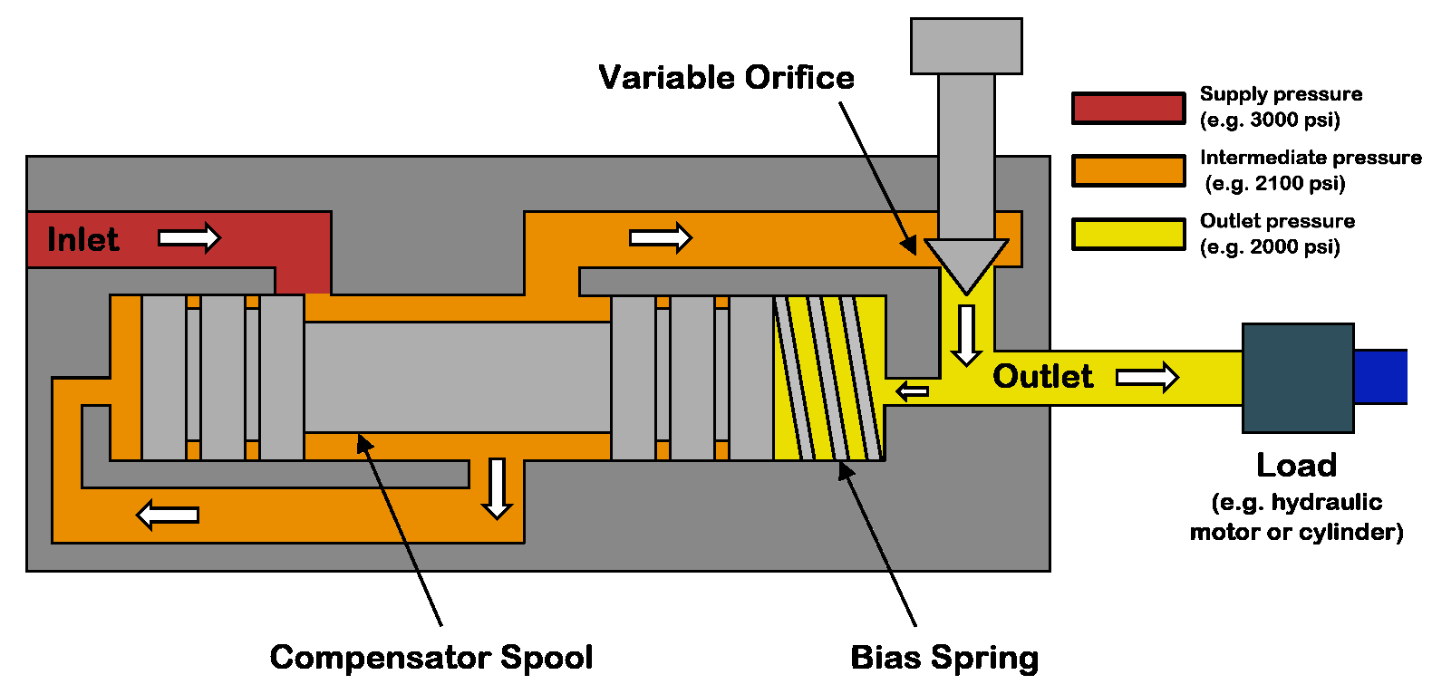
A pressure compensator is a device built into some pumps for the purpose of automatically reducing (or stopping) pump flow if system pressure sensed on the pump outlet port, should rise above a pre-set desired maximum pressure (sometimes called the "firing" pressure). The compensator prevents the pump from being overloaded if an overload is placed on the hydraulic system.
A compensator is built into the pump at the factory and usually cannot be added in the field. Any pump built with variable displacement can be controlled with a compensator. These include several types of axial piston pumps and unbalanced (single lobe) vane pumps. Radial piston pumps can sometimes be built with variable displacement but do not lend themselves readily to this action. Most other positive displacement pumps including internal and external gear, balanced (double lobe) vane, gerotor, and screw types cannot be built with variable displacement.
Figure 1 is a schematic of a check valve axial piston pump, variable displacement, controlled with a pressure compensator. The pistons, usually 5, 7, or 9 in number, are stroking inside a piston block which is keyed to and is rotating with the shaft. The left ends of the pistons are attached through swivel joints, to piston shoes which bear against and slide around on the swash plate as the piston block rotates. The swash plate itself does not rotate; it is mounted on a pair of trunnions so it can swivel from neutral (vertical) position to a maximum tilt angle. The angle which the swash plate makes to the vertical causes the pistons to stroke, the length of stroke being proportional to the angle. Normally, at low system pressures, the swash plate remains at its maximum angle, held there by spring force, hydraulic pressure, or by the dynamics of pump construction, and pump flow remains at maximum. The compensator acts by hydraulic pressure obtained internally from the pump outlet port. When pump pressure rises high enough to over-come the adjustable spring behind the compensator piston, the "firing" pressure has been reached, and the compensator piston starts to pull the swash plate back toward neutral, reducing pump displacement and output flow. The spring in the compensator can be adjusted for the desired maximum or "firing" pressure.
Under working conditions, on a moderate system overload, the compensator piston reduces the swash plate angle just enough to prevent the system pressure from exceeding the "firing" pressure adjusted on the compensator. On severe overloads the compensator may swing the swash plate back to neutral (vertical) to reduce pump flow to zero.
Maximum Displacement Stops. Some pumps are available with internal stops to limit the tilt angle of the swash plate. These stops limit the maximum flow and limit the HP consumption of the pump. They may be fixed stops, factory installed and inaccessible from the outside, or they may be externally adjustable with a wrench.
Manual Control Lever. Some pressure compensated pumps, especially hydrostatic transmission pumps, are provided with an external control lever to enable the operator to vary the swash plate angle (and flow) from zero to maximum. On these pumps the pressure compensator is arranged to override the manual lever and to automatically reduce the swash plate angle if a system overload should occur even though the operator control lever is still shifted to maximum displacement position.
Basically the pressure compensator is designed to unload the pump when system pressure reaches the maximum design pressure. When the pump is unloaded in this way, there is little HP consumed and little heat generated even though pressure remains at the maximum level, because there is no flow from the pump.
Variable displacement pumps are usually more expensive than fixed displacement types, but are especially useful in systems where several branch circuits are to be supplied from one pump, and where full pressure may be required simultaneously in more than one branch, and where the pump must be unloaded when none of the branches is ill operation. If individual 4-way valves are used in each branch, each valve must have a closed center spool. The inlet ports on all 4-way valves must be connected in parallel across the pump line. However, if all branch circuits are operated from a bank valve of the parallel type, a pressure compensated variable displacement pump may not be necessary; a fixed displacement pump, gear, vane, or piston, may serve equally well because the bank valve will unload the pump when all valve handles are placed in neutral, but when two or more handles are simultaneously shifted, their branch circuits will automatically be placed in a parallel connection.
As in all hydraulic systems, more pump oil will flow to the branch with the lightest load. Bank valve handles can be modulated to equalize the flow to each branch. When individual 4-way valves are used in each branch, flow control valves may be installed in the branch circuits and adjusted to give the flow desired in each branch.
Figure 2 shows a multiple branch circuit in which a variable displacement pump is used to advantage. Individual 4-way valves, solenoid operated, are used for each branch, and they have closed center porting. Please refer to Design Data Sheet 54 for possible drift problems on a pressure manifold system. A pressure relief valve is usually required even with a pressure compensated pump due to the time interval required for the swash plate to reduce its tilt angle when a sudden overload occurs. The relief valve will help absorb part of the pressure spike generated during this brief interval. It should be adjusted to crack at about 500 PSI higher than the pressure adjustment of the compensator piston spring to prevent oil discharge across it during normal operation.
All hydrostatic transmission systems use a variable displacement pump with pressure compensator, and often combine the compensator with other controls such as the horsepower input limiter, load sensing, flow sensing, or constant flow control.
© 1990 by Womack Machine Supply Co. This company assumes no liability for errors in data nor in safe and/or satisfactory operation of equipment designed from this information.

www.powermotiontech.com is using a security service for protection against online attacks. An action has triggered the service and blocked your request.
Please try again in a few minutes. If the issue persist, please contact the site owner for further assistance. Reference ID IP Address Date and Time 8bf2006c85a66667641f5dd58dcb3d35 63.210.148.230 03/12/2023 08:48 AM UTC
A hydraulic pump is a mechanical device that converts mechanical power into hydraulic energy. It generates flow with enough power to overcome pressure induced by the load.
A hydraulic pump performs two functions when it operates. Firstly, its mechanical action creates a vacuum at the pump inlet, subsequently allowing atmospheric pressure to force liquid from the reservoir and then pumping it through to the inlet line of the pump. Secondly, its mechanical action delivers this liquid to the pump outlet and forces it into the hydraulic system.
The three most common hydraulic pump designs are: vane pump, gear pump and radial piston pump. All are well suited to common hydraulic uses, however the piston design is recommended for higher pressures.
Most pumps used in hydraulic systems are positive-displacement pumps. This means that they displace (deliver) the same amount of liquid for each rotating cycle of the pumping element. The delivery per cycle remains almost constant, regardless of changes in pressure.
Positive-displacement pumps are grouped into fixed or variable displacement. A fixed displacement pump’s output remains constant during each pumping cycle and at a given pump speed. Altering the geometry of the displacement chamber changes the variable displacement pump’s output.
Fixed displacement pumps (or screw pumps) make little noise, so they are perfect for use in for example theatres and opera houses. Variable displacement pumps, on the other hand, are particularly well suited in circuits using hydraulic motors and where variable speeds or the ability to reverse is needed.
Applications commonly using a piston pump include: marine auxiliary power, machine tools, mobile and construction equipment, metal forming and oil field equipment.
As the name suggests, a piston pump operates through pistons that move back and forth in the cylinders connected to the hydraulic pump. A piston pump also has excellent sealing capabilities.
A hydraulic piston pump can operate at large volumetric levels thanks to low oil leakage. Some plungers require valves at the suction and pressure ports, whilst others require them with the input and output channels. Valves (and their sealing properties) at the end of the piston pumps will further enhance the performance at higher pressures.
The axial piston pump is possibly the most widely used variable displacement pump. It’s used in everything from heavy industrial to mobile applications. Different compensation techniques will continuously alter the pump’s fluid discharge per revolution. And moreover, also alter the system pressure based on load requirements, maximum pressure cut-off settings and ratio control. This implies significant power savings.
Two principles characterise the axial piston pump. Firstly the swash plate or bent axis design and secondly the system parameters. System parameters include the decision on whether or not the pump is used in an open or closed circuit.
The return line in a closed loop circuit is under constant pressure. This must be considered when designing an axial piston pump that is used in a closed loop circuit. It is also very important that a variable displacement volume pump is installed and operates alongside the axial piston pump in the systems. Axial piston pumps can interchange between a pump and a motor in some fixed displacement configurations.
The swivel angle determines the displacement volume of the bent axis pump. The pistons in the cylinder bore moves when the shaft rotates. The swash plate, in the swash plate design, sustain the turning pistons. Moreover, the angle of the swash plate decides the piston stroke.
The bent axis principle, fixed or adjustable displacement, exist in two different designs. The first design is the Thoma-principle with maximum 25 degrees angle, designed by the German engineer Hans Thoma and patented in 1935. The second design goes under the name Wahlmark-principle, named after Gunnar Axel Wahlmark (patent 1960). The latter features spherical-shaped pistons in one piece with the piston rod and piston rings. And moreover a maximum 40 degrees between the driveshaft centre-line and pistons.
In general, the largest displacements are approximately one litre per revolution. However if necessary, a two-litre swept volume pump can be built. Often variable-displacement pumps are used, so that the oil flow can be adjusted carefully. These pumps generally operate with a working pressure of up to 350–420 bars in continuous work
Radial piston pumps are used especially for high pressure and relatively small flows. Pressures of up to 650 bar are normal. The plungers are connected to a floating ring. A control lever moves the floating ring horizontally by a control lever and thus causes an eccentricity in the centre of rotation of the plungers. The amount of eccentricity is controlled to vary the discharge. Moreover, shifting the eccentricity to the opposite side seamlessly reverses the suction and discharge.
Radial piston pumps are the only pumps that work continuously under high pressure for long periods of time. Examples of applications include: presses, machines for processing plastic and machine tools.
A vane pump uses the back and forth movement of rectangle-shaped vanes inside slots to move fluids. They are sometimes also referred to as sliding vane pumps.
The simplest vane pump consists of a circular rotor, rotating inside of a larger circular cavity. The centres of the two circles are offset, causing eccentricity. Vanes slide into and out of the rotor and seal on all edges. This creates vane chambers that do the pumping work.
A vacuum is generated when the vanes travel further than the suction port of the pump. This is how the oil is drawn into the pumping chamber. The oil travels through the ports and is then forced out of the discharge port of the pump. Direction of the oil flow may alter, dependent on the rotation of the pump. This is the case for many rotary pumps.
Vane pumps operate most efficiently with low viscosity oils, such as water and petrol. Higher viscosity fluids on the other hand, may cause issues for the vane’s rotation, preventing them from moving easily in the slots.
Gear pumps are one of the most common types of pumps for hydraulic fluid power applications. Here at Hydraulics Online, we offer a wide range of high-powered hydraulic gear pumps suitable for industrial, commercial and domestic use. We provide a reliable pump model, whatever the specifications of your hydraulic system. And we furthermore ensure that it operates as efficiently as possible.
Johannes Kepler invented the gear pump around year 1600. Fluid carried between the teeth of two meshing gears produces the flow. The pump housing and side plates, also called wear or pressure plates, enclose the chambers, which are formed between adjacent gear teeth. The pump suction creates a partial vacuum. Thereafter fluid flows in to fill the space and is carried around the discharge of the gears. Next the fluid is forced out as the teeth mesh (at the discharge end).
Some gear pumps are quite noisy. However, modern designs incorporating split gears, helical gear teeth and higher precision/quality tooth profiles are much quieter. On top of this, they can mesh and un-mesh more smoothly. Subsequently this reduces pressure ripples and related detrimental problems.
Catastrophic breakdowns are easier to prevent with hydraulic gear pumps. This is because the gears gradually wear down the housing and/or main bushings. Therefore reducing the volumetric efficiency of the pump gradually until it is all but useless. This often happens long before wear causes the unit to seize or break down.
Can hydraulic gear pumps be reversed? Yes, most pumps can be reversed by taking the pump apart and flipping the center section. This is why most gear pumps are symmetrical.
External gear pumps use two external spur gears. Internal gear pumps use an external and an internal spur gear. Moreover, the spur gear teeth face inwards for internal gear pumps. Gear pumps are positive displacement (or fixed displacement). In other words, they pump a constant amount of fluid for each revolution. Some gear pumps are interchangeable and function both as a motor and a pump.
The petrochemical industry uses gear pumps to move: diesel oil, pitch, lube oil, crude oil and other fluids. The chemical industry also uses them for materials such as: plastics, acids, sodium silicate, mixed chemicals and other media. Finally, these pumps are also used to transport: ink, paint, resins and adhesives and in the food industry.
Mathematical calculations are key to any type of hydraulic motor or pump design, but are especially interesting in the gerotor design. The inner rotor has N teeth, where N > 2. The outer rotor must have N + 1 teeth (= one more tooth than the inner rotor) in order for the design to work.

Another option is to utilize a load sense compensator. With a load sense compensator, this compensator will include a lighter spring setting to control the swash plate. Upstream pressure is ported into a load sense port on the pump, as the pressure requirement increases, the pressure acts against the load sense piston. Once the pressure requirement is higher than the offset, the pump swash plate angle changes and the pump begins to increase flow, by increasing the swash plate angle, until we have enough pressure to balance the piston. Once balanced, the flow remains steady until the load changes.
The offset pressure is normally 200-300 PSI. With a load sense compensator, the pump produces what the load requires plus the spring offset, normally 200-300 PSI.
This system will also utilize a standard compensator so if the system pressure increases enough, the pressure compensator will take control and reduce the swash plate angle to reduce the pressure.
Let’s look at my initial application but this time, it has a varying load. They conveyor requires 1500 PSI to move 50% of the time, but the balance of the time the system requires between 2250-2500 PSI to move the load.
With a standard pressure compensator, you would have to set the pump at 2600 PSI to accomplish the work. When the work only requires 1500 PSI, the pump will be trying to produce 2600 PSI. Fifty percent of the time, your system will be operating at 1100 PSI of inefficiency, which means heat. With a load sense compensator, when the load requires 1500 PSI, the pump will actually produce about 17-1800 PSI. Yes, this is 300 PSI inefficient, but that is much better than 1100 PSI inefficient.
With a varying load, the load sense is a much better system. For additional control, you can utilize an electronic proportional flow control or throttle. You can use an electrical signal to vary the hydraulic signal which is received by the pump’s load sense line. This would give you full electronic control of the amount of flow the pump produces.
There are additional control options which allow you to remotely control the pressure compensator. With this remote compensator control, you can set 2 or more different system pressures. With the ability of a variable piston pump to build 5,000 or more PSI; the additional setting can be used when operating components with a much lower pressure requirement.
The next control is a torque limiting or HP limiting control. By adding an additional spring and piston, you can set a pump to always maximize its allowable input torque, therefore, maximizing output flow and pressure at a defined setting.
In this application, you are operating large bore, long strong cylinder. The cylinder has a 10” bore and 150” stroke. During most of the stroke, the cylinder is not doing very much work and can operate at 800-1200 PSI. During the last 20” of stroke, we want to hit our system pressure of 4500 PSI, but we can move much slower.
Our pump has an output of 15 CIR, a maximum flow of about 113 gallons at 1750 RPM. Our prime mover is an electric motor, 75HP with a 1.15 service factor. I want to keep my cylinder moving as fast as possible, but I also want to ensure that I never exceed a power demand 82 HP.
At 82 HP, the pump can produce 1254 PSI at full output, 113 GPM. As the load requires more pressure, the pump will begin to reduce flow and increase pressure. At 90 GPM flow, the system will produce about 1560 PSI; at 60 GPM we can get almost 2350 PSI. At 4500 PSI, the pump flow will be reduced to about 31 GPM. The advantage of this pump is that the internal controls of the pump are adjusting to maximize flow and pressure at all times without exceeding the available HP.
If I wanted to use a pump which could produce 113 gallons of flow at 4500 PSI, I would need 296 HP. If I choose a 75 HP motor with a pressure compensated variable piston pump, the motor would stall before the pressure compensator could kick in and reduce the pump flow. Depending on the load, a load sense pump could also stall the 75 HP motor if the load pressure is high enough to use up the HP before the pressure compensator kicks in. With a torque limiting (HP) control, we utilize the full limits of the prime mover and maximize power usage.

Pressure compensated hydraulic systems are becoming more popular due to their high efficiencies. These systems run great when properly applied but there are things you should know before you run a pressure compensated system.
Heat and contamination are the two leading causes of failure in a hydraulic system; if both aren’t properly maintained then your system will inevitably fail. For now, let’s focus on the heat. Heat can be a hard culprit to chase down when starting a prototype system. Two major factors of heat generation in a pressure compensated system are relief valve heat and standby heat.
When first starting up a pressure compensated hydraulic system, you have to always set the pressures on the pump’s compensator and the main system relief valve. Doing this properly is the key to avoiding heat generation. The compensator must always be set at a lower pressure than your system relief valve. If the system relief is lower or equal to the compensator setting, you will have constant flow over the main relief, which will then produce a ton of heat until the system fails. It is a safe practice to set your system relief valve 300 PSI above what your compensator is set at. This will ensure no flow is going over the relief during normal working conditions but will still protect your systems from any pressure spikes.
A cause of heat that is rarely considered – and to some, completely unknown – is the standby heat. The benefit of a pressure compensated pump is that it will destroke once the pressure builds to the compensator setting, therefore cutting off the pump flow but still maintaining the desired pressure. The downfall to this is that if you are running at a high pressure and are destroked at the compensator pressure, you are creating heat inside the case which will flow out of the case drain line and into your reservoir. Many may think of this as a minor amount of heat, but if a system is left sitting in this high-pressure standby state, the heat can become a major factor in your system. Below is a chart that shows just how much heat can be created at different pressures and speeds when sitting at compensator pressure.

Piston pumps are durable and relatively simple devices. A basic piston pump is made up of a piston, a chamber, and two valves. The pump operates by driving the piston down into the chamber, thereby compressing the media inside. In a hand pump, this is usually air. Once the pressure of the air exceeds that of the outlet valve spring, the compressed media goes through the open outlet valve. When the piston is drawn back up, it opens the inlet valve and closes the outlet valve, thereby utilizing suction to draw in new media for compression.
Although somewhat expensive, piston pumps are among the most efficient types of pumps. They have an excellent pressure rating (as high as 10,000 psi), but their design makes them susceptible to contaminants. They provide an excellent solution for many high-pressure hydraulic oil pumping applications.
Axial piston pumps are positive displacement pumps that use multiple cylinders grouped around a central axis. The group of cylinders, usually containing an odd number, is called a cylinder block. The pistons within each cylinder are attached to a swashplate. The swashplate is also known as a cam or wobble plate and attaches to a rotating shaft. As the shaft turns, the angle of the swashplate changes, which drives the pistons in and out of their respective cylinders.
Since the swashplate is at an angle to the axis of rotation, the pistons must reciprocate axially as they orbit around the cylinder block axis. The axial motion of the pistons is sinusoidal. As a piston rises, it moves toward the valve plate. At this point in the rotation, the fluid trapped between the buried end of the piston and the valve plate is expelled to the pump"s discharge port through one of the valve plate"s semi-circular ports. As the piston moves back toward the valve plate, the fluid is pushed through the discharge port of the valve plate.
Axial piston pumps can be designed as variable displacement piston pumps, making them very useful for controlling the speeds of hydraulic motors and cylinders. In this design, a swashplate is used to vary the depth to which each piston extends into its cylinder as the pump rotates, affecting the volume of discharge. A pressure compensator piston is used in some designs to maintain a constant discharge pressure under varying loads. Cheaper pressure washers sometimes use fixed-rate designs.
In a typical pressure-compensated pump, the swashplate angle adjusts through the action of a valve using pressure feedback to make sure that the pump output flow is precisely enough to maintain a designated pressure. If the load flow increases, the pressure momentarily decreases, but the pressure-compensation valve senses the decrease and then increases the swashplate angle to increase the pump’s output flow, restoring the desired pressure.
Axial piston pumps can contain most of the necessary circuit controls intrinsically by controlling the swash-plate angle, to regulate flow and pressure. They are very reliable and can allow the rest of the hydraulic system to which they’re attached to be very simple and inexpensive.
They are used to power the hydraulic systems of jet aircrafts, being gear-driven off of the turbine engine"s main shaft, and are often used for automotive air conditioning compressors for cabin cooling. The design of these pumps meets the limited weight and space requirement in the vehicle"s engine bay and reduces vibrations.
Pressure washers also use these pumps, and axial reciprocating motors are used to power many machines. They operate on the same principles as axial piston pumps, except that the circulating fluid is provided under substantial pressure and the piston housing rotates and provides shaft power to another machine. A typical use of an axial reciprocating motor is powering small earthmoving machines such as skid loader machines.
This guide provides a basic understanding of axial piston pumps. To find out more about other types of pumps, read our guide here. For more information on related products, consult our other product guides or visit the Thomas Supplier Discovery Platform to locate potential sources or view details on specific products.

series: PCP8max flow: 7.8 GPMHyvair’s line of pressure compensated industrial piston pumps (PCP) are stocked with displacements from 0.49 cu.in/r. (8.0cc) to 4.27 cu.in/r. (70.0cc) and continuous pressure up to 3,000 PSI. All sizes in our industrial line are available with multiple control options from load sensing to dual pressure solenoid. Through drives are available on all pump sizes except the PCP33. The semi-cylindrical swash plate design allows for smooth, stable operation, increases efficiency and reduced noise by sealing pressure on its face. catalog pdf Cad File
Hyvair Corp. distinguishes itself from other component and system companies with total customer service. From design support in the earliest phases of your project, to just-in-time deliveries to meet your customer"s production schedule, Hyvair works with you as a team member - not just a supplier.

Pressure compensation is the control of flow by compensating for the changes in load pressure. Most hydraulic systems today use pre-compensation as a means of maintaining consistent flow from an orifice or spool. However, there are applications when post-compensation has advantages over pre-compensation.
The fundamental difference is that with pre-compensation, the pressure drop across the orifice or spools is determined by the compensator. With post-compensation, the pressure drop is determined by the load sense (LS) spring inside the pump.
In post-compensated systems with multiple functions, the pump flow is divided at a fixed ratio. If flow settings exceed the pump output capability, the flow is reduced to each function at a fixed ratio. This is why post-compensation is sometimes referred to as “flow sharing”.
In post-compensated circuits, the pressure drop across each valve is determined by the load sense spring in the pump and all valves or orifices will have the same pressure drop. The load sense differential, sometimes referred to as standby, decreases when the pump cannot satisfy the total demand. All pressure compensators reference the highest load of the various functions.
The benefits include high efficiency under partial load and/or partial speed conditions and all functions slow down together at a fixed ratio when the pump cannot fully satisfy demand.
In the example below, the pump differential, or standby, is 200 PSI. The load sense pump will develop enough pressure to overcome the load and maintain a 200 PSI differential. The pressure drop across the valve or orifice remains fixed and is calculated by: system pressure minus the highest load pressure minus the compensator spring value.
The circuit below is an example of the flow sharing aspect. When another function is operated and the pump cannot fully satisfy the flow demand, the differential decreases. The pressure drop across each valve or orifice is reduced at the same fixed ratio, so the flow is divided, or shared, equally. In this example, each valve is fully open so total pump flow is shared equally between the functions.
So what happens when the functions require different flows and the pump cannot fully satisfy the total flow demand? The pump flow will be divided into the ratio of each function to total flow available. In the example below, the theoretical total flow demand is 42 GPM. The ratio of the function flow demand to total theoretical flow demand multiplied by the maximum pump flow is the resulting actual flow from each valve.
Post-compensation will increase stability and control in systems where demand can exceed the pump’s flow output. Because of its increased efficiency under partial load conditions, the compensator saves horsepower and reduces heat. It will also make the initial movement of actuators more predictable and provide better operator control.

The known benefit is that a pressure compensated variable displacement pump operates at a low standby pressure when no functions are active. When a function operates that requires less than full flow and pressure, the pump produces only the required flow at a pressure slightly higher than the actual load pressure. Typical hydraulic courses have graphs showing the power savings when compared to a fixed displacement pump or a variable displacement pressure compensated pump operating at compensator pressure when the theoretical output load pressure and flow requirement is less than the pump capacity. These examples only show the potential energy savings when one pump controls one actuator. When one pump supplies multiple actuators operating at different pressure and flow requirements, any potential energy savings rarely matches the optimum value provided by the classroom example. Interconnecting multiple pumps to work together can also be challenging.
Load sense has become so widely accepted that many manufacturers have valves designed specifically for load sense applications. The valves have a series of internal shuttle valves to send the highest load pressure requirement to the load sense output port. The typical valve also has ports to “daisy chain” load sense signals from other valves, so the highest load pressure requirement supplies the load sense port on the pump. The valve at the end of the daisy chain bleeds off the load sense pressure when no valve is actuated.
There are several drawbacks to load sense control that make applying it challenging in some applications. The main issues relate to the load sense feedback line itself. You typically use a 1/4-inch (6-mm) or 3/8-inch (10-mm) diameter hose. In cold environments, the oil in the line can be highly viscous and fail to produce an adequate signal to pump. Also, on large machines with multiple valve locations over long distances, the time delay for the pressure signal to reach the pump load sense port results in sluggish reaction. If the load pressure changes increase and decrease too quickly, the pump overcompensates and causes instability. A common solution is to add a bleed orifice at the pump for a small continuous flow that keeps the fluid warm and less viscous. The orifice also helps dampen pressure spikes, allowing the pump to respond in a more stable manner. This bleed orifice can require an increase to the load sense line to accommodate the associated pressure drop. Occasionally flow controls with a bypass check are added to the load sense circuit to stabilize the system. In extreme cases, accumulators are also utilized.
As electrohydraulic proportional directional control valves with related digital controllers become more popular, the possibility of using electronic load sensing also becomes more practical and offers other advantages. While you can use electronic load sensing with manually operated valves, it may not offer some of the additional benefits.
Electronic load sense control is accomplished by replacing the load sense feedback line with pressure transducers at each valve. Instead of daisy chaining multiple valves together, each valve can have its own dedicated transducer. Each transducer sends a signal to an electronic control module. The pump control changes from a load sense control, which requires a pressure signal to the load sense port, to a remote pressure control that sends a pressure signal to a remote relief valve. The remote relief valve then adjusts the compensator pressure to match the load pressure up to the main pump compensator setting. The proportional pilot relief is controlled by the same electronic controller that is receiving the signal from the multiple pressure transducers. Simple systems with minimal outputs or manually operated valves may only require one controller for the entire machine. For complex systems requiring multiple transducer inputs, multiple proportional directional valves, and more than one pump control output, it may be more practical to use a dedicated controller for the load sense functions. The program evaluates the pressure transducer inputs, then outputs the highest pressure command to the pump pilot pressure control. Many remote proportional controls on the pump still have some form of a differential spring; or you can add a differential pressure to the control signal.
The first benefit of electronic load sense is the almost instant response of a pressure signal. Cold viscous oil, excessive line lengths, or the capacitance of the pilot line do not affect the signal.
Electronic load sensing can provide variable differential settings. The common load sense control on the pump has a fixed differential or standby pressure setting. It can be tuned during commissioning, but it is typically not adjusted after that. The nominal pressure can vary from 15 to 35 bar (220 to 500 psi) depending on the pump and valve requirements. When a bleed orifice is installed, the flow-pressure drop also affects the differential setting and pump response. The electronic load sense control responds not only to the pressure signal, it also provides a differential pressure that responds to the valves being commanded. In one application, a feed cylinder had to be limited in the retract force. In this case the cylinder was the only function active for that part of the cycle. Limiting the pilot pressure when that specific function was actuated to retract the cylinder limits the retract force. An added benefit was that the load sense pressure was also mapped to the retract command. A slight command increases the pump pressure setting slightly; the higher the operator command, the more the proportional directional valve opened and the pump pilot pressure increased. This resulted in a unique feathering ability to retract the cylinder.
Another benefit is the ability to ramp or delay the load sense pressure command at the pump. One application has a high standby pressure, nominally 35 bar (500 psi). When a function actuates, the differential pressure gradually lowers to 15 bar (200 psi) over the load pressure. The result is fast response when the valve shifts, followed by reduced pressure drop across the valve when the function is operating and the flow is higher.
Fan applications using load sense pressure compensated pumps often result in oscillation that requires considerable tuning. The challenge is that the oscillation is related to the pressure spiking when accelerating the fan, then dropping because the pump compensates at the same time the fan motor begins turning, and the fan inertia keeps the motor spinning. This oscillation can be alleviated by ramping the control pressure up relative to the commanded fan speed instead of the pressure. Since fans have a characteristic speed-torque curve, it can be programmed into the control without too much difficulty.
Because electronic load sensing uses a remote pressure control on the pump, a sophisticated control that calculates the flow requirements based on the summing proportional valve command values and the load pressures also provides a form of power limiting.
If an application requires a failure mode to ensure the functions can still operate, an inverse proportional relief can be used for the pilot control. The inverse proportional relief operates at full pressure with no command and reduces pressure as the command increases. The default condition causes the pump to operate as a simple pressure compensated pump if the load sense control program experiences a failure, such as a broken wire or other damage.
Electronic load sensing offers control options that in the past were either impractical or impossible. By combining the faster processing speeds of modern controllers with added I/O capacity, electronic load sense control optimizes the differential pressure of a conventional load sense system. Electronic controllers can now integrate system pressure with flow requirements to provide power-limiting features for a specific application.•

When servicing and troubleshooting hydraulic equipment, we all make mistakes. After all, we are human. These mistakes can cost us in many ways and almost always result from a lack of competent training. Working around hydraulic machines can be a complex exercise, as it involves a great deal of science. To avoid these common mistakes, a logical approach based on knowledge (including knowing the function of each hydraulic component) and sound troubleshooting principles is required.
Hydraulic systems operate at high pressures and flow rates. As a result, they have the inherent ability to burn, maim or kill. In addition, leakage of hydraulic oil can lead to slips and falls. However, knowing these facts as well as the function of each hydraulic component are only the “tip of the iceberg” when preventing accidents.
When working around hydraulic systems, the proper PPE (Personal Protection Equipment) must be worn. At a minimum, safety glasses or “full face” protection must be worn. Long sleeves and gloves should be worn to protect from burns and cuts. In addition, steel- or composite-toed safety shoes should be worn especially when replacing heavy components such as pumps and cylinders.
Since a great deal of energy is contained in a hydraulic system, most facilities will have LOTO (Lock Out / Tag Out) procedures to be followed prior to servicing the equipment. The goal of these LOTO procedures is to put the system in a “zero-energy state” to prevent the sudden release of energy. However, I know of many cases where these procedures were followed to the letter and personnel were still injured or killed while servicing a machine.
This is because of a lack of knowledge on the part of many people who write the LOTO procedures. They believe that their procedures are putting the machine in a zero-energy state, when there may in fact still be energy stored in the system. This is especially true wherever accumulators are used. Most systems will contain an automatic and/or manual dump valve (usually located in a block at the base of the accumulator) which will allow the pressurized oil in the accumulator to bleed to the reservoir when the system is turned off. If the automatic dump valve fails closed or the manual dump valve is not opened, pressurized oil will be maintained in the accumulator. If a line or component is removed, then someone may suffer an injection injury. Initially, an injection injury may seem minor. However, this is very serious as most hydraulic fluids are extremely toxic and any delay in proper medical treatment can lead to amputations or death.
One common mistake is to assume that if a pressure gauge reads zero pressure, then it is safe to remove lines and components. However, most systems will have a check valve for pump isolation, and the gauge is installed on the pump side of this check valve instead of the accumulator side. When the pump is turned off, the oil will bleed to the reservoir through the internal clearances in the pump. The technician will then think that the pressure is zero and will have no way of knowing if the pressurized oil in the accumulator has been released. On any system using this type of check valve, a gauge should be installed at or near the accumulator and a manual accumulator dump valve should be installed. Opening the dump valve should then become part of the LOTO procedures. This is the only way to be sure that all the energy has been released.
As I spend time with plant personnel, I find that many people do not understand the difference between pressure and flow. Some even believe that pressure and flow are the same thing! This is why it is a common misconception that pressure must be increased to increase actuator speed. While it is true that pressure will increase actuator speed when standard (non-pressure compensating) flow controls are used, it is important to understand why this occurs.
One of the factors affecting the flow through a flow control is the difference between the inlet and outlet pressures. The pressure downstream of a flow control will be determined by the pressure required to move the load. This pressure will remain fairly constant, so long as the weight of the load does not change. The pressure at the flow control inlet will be at or near the pump compensator setting (when using a pressure compensating pump), so long as the pump can deliver sufficient volume. The difference between these two pressures is known as the pressure drop. Assuming the oil temperature and viscosity remain constant, an increase in pressure drop will result in increased flow through the flow control. This will in turn cause an increase in the actuator speed. The problem with this method is that the pressure has been increased well above the pressure required to do the work required. This only leads to shock and decreased component and hose life. It is also impossible to change the speed in one actuator without affecting the speed of the other actuators when using this method. When the speed of an actuator needs to be changed, it should only be done by adjusting the flow controls in the specific circuit. Just remember that the rate of oil flow controls speed, not pressure!
Another misconception pertains to the function of a hydraulic pump. I have found that about 60 to 70% of people believe that a pump makes pressure. This is understandable, as some so-called “hydraulic instructors” are teaching this to their students. In addition, a pressure compensated pump has an adjustment (compensator) that will change the pressure at the outlet of the pump, which adds to the confusion. However, this is simply NOT the case! The function of a hydraulic pump is to produce flow. As this flow produced by the pump encounters resistance, pressure will build. If you were to direct the pump volume directly to the reservoir, no appreciable pressure would be generated (as long as there is no resistance to the flow). It is important to remember that we must have two things to build pressure in a hydraulic system: flow (which the pump produces) and resistance (which is produced by the load). In the case of a pressure compensated pump, the pump will de-stroke to near zero volume when no flow is required.
When a machine failure occurs, many technicians will simply start changing parts until the machine starts working again. I discovered this in my 25+ years in repairing hydraulic components. I found that approximately 80% of the components I received for repair had absolutely nothing wrong with them! In our hydraulic troubleshooting workshops, we stress five elements necessary for troubleshooting and maintaining hydraulic systems:
This is the first tool that should be used when troubleshooting a hydraulic issue. It is nearly impossible to determine the cause of an issue if one does not fully understand how all the components are interconnected.
With a few exceptions, a hydraulic component can be tested without removing it from the system. This is facilitated by an understanding of the function and internal operation of various components.
It is very important to understand how to properly adjust the various components on the system. Having an improperly adjusted component is equivalent to having the wrong component installed.
Knowing the proper reliability checks to make can significantly reduce machine failures. These include temperature, pressure and speed checks. Of course, these checks should be made when the machine is operating normally to establish a baseline reference for future troubleshooting.
When a machine is not operating properly, there is usually only one component that has failed. Once that component is isolated, a replacement is sometimes selected simply because it looks the same and fits on the machine. However, pumps and valves can have many internal differences which can affect their operational characteristics. The model codes should be carefully compared, as each number or letter indicates a particular feature of the component. If there are any differences, then the manufacturer’s documentation should be consulted to determine what that difference is. On several occasions, I have traveled several hours to troubleshoot an issue only to find that the maintenance personnel had installed the wrong component.
When replacing a hydraulically piloted directional valve, careful consideration should be made as to the piloting configuration. These valves will have two additional ports in addition to the familiar “P”, “T”, “A” and “B” ports. One port will be marked “X” (pilot pressure) and the other will be marked “Y” (pilot drain). In an externally piloted and drained valve, the oil to and from the pilot valve is directed through these ports. If the valve is configured in this way and there is no pilot pressure at port “X”, the main spool of the valve will not shift and the actuator will not move. Many valve manufacturers use plugs inside the main body to change the piloting configuration. The manufacturer’s documentation will usually provide instructions for changing the configuration to the specific machine requirements.
Most maintenance personnel do an excellent job at changing pressure and return filters at specified intervals. However, the reservoir is usually not given any attention. Reservoirs are normally sized according to the total pump volume, but the reservoir size is also factored in to determine how much heat is removed from the system during operation. The outside of the reservoir should be cleaned regularly to ensure that a portion of the heat in the oil is transferred to the atmosphere through thermal transfer.
One filter that is often overlooked during maintenance is the breather filter. Many see the breather filter as no more than a “cap” that can be removed for adding oil to the system. However, it is a filter and should be serviced as such. As the system operates and cylinders extend and retract, the oil level in the reservoir will rise and drop. As the oil level rises, air is ported from the reservoir to the atmosphere through the breather filter. Likewise, atmospheric air is drawn into the reservoir as the oil level drops. The breather filter prevents airborne contaminants in the air from entering the reservoir when this occurs. I recently did a reliability assessment on a loading system at a paper mill. I noticed that the breather filter was severely deteriorated and looked as if it had not been changed in quite a while. None of the maintenance personnel could tell me if or when the breather filter had been changed. Considering its condition, it is likely that the breather filter had been in place since the system was installed 34 years prior!
Many systems use suction strainers to prevent large particles from entering the pumps. These strainers are often located inside the reservoir, so they tend to go without service. However, if these strainers become contaminated, the vacuum at the pump suction will increase and cause cavitation of the pumps. This cavitation will lead to pump damage. Some time ago, I received a call from a customer in Ontario, Canada regarding a pump that had been replaced several times. Each pump was very noisy, and they were perplexed as to why the noise remained even after they changed the pump. Of course, I immediately suspected cavitation, so I asked them to drain the tank and inspect the suction strainer. They found the suction strainer (pictured at right) had become contaminated and was causing cavitation of the pump. The strainer was cleaned and their problem was solved. Of course, inspection and servicing of the suction strainers is now a part of their regular preventative maintenance procedures!
Approximately 95% of hydraulic component failures are a result of contamination. One of the ways contamination can enter a hydraulic system is through adding unfiltered new oil. When hydraulic oil is first refined, it is relatively clean. However, once the oil is transferred to containers and transported, it can and will become contaminated. Several years ago, I received a call from a customer concerning a servo valve which I had repaired 8 years prior. He informed me that the valve had been in service all this time but had recently become very “sluggish” and eventually stopped working altogether. He advised that he was sending the valve in for repair, but that it was “no hurry” since he had a new valve that he had just installed and the system was again operational. Two days later, I received the failed valve for repair. I proceeded with an evaluation of the valve and found that the internal pilot filter was totally plugged with contaminants. I initially thought nothing of this since the valve had been in service for 8 years. However, I received yet another call from the customer advising that the new valve had failed after only three days! I asked if he had recently performed any maintenance on the system. He advised that they had recently serviced and cleaned the inside of the reservoir and had refilled the reservoir with new oil. When I asked him if the new oil had been filtered, he told me that it was new oil so it did not need to be filtered. This is a very common misconception and he was surprised to learn that he had inadvertently contaminated his system by refilling the reservoir with unfiltered new oil. In effect, he was effectively straining the contaminants in the oil through his servo valves.
Many systems incorporate a fill port for refilling the reservoir so that the new oil is ported through a filter. Standalone filter carts are also available for refilling the reservoir. Either way, any new oil added to the reservoir should be filtered. This is especially important on systems utilizing pressure compensated pumps and servo / proportional valves.
Although hydraulic machines have many advantages over other means of performing work, they are not immune to failures and downtime. The key to keeping them running is knowledge. In addition, most accidents can be prevented by a proper understanding of the fundamentals and science involved in hydraulic system operation.

Piston pumps are typically much more complicated and are often available in wither fixed or, commonly, variable displacement configurations and with pressure compensation. These are big words that mean that piston pumps can usually adapt to the system pressure, providing maximum efficiency and flexibility. They are often used in “closed center” systems where the pump displacement varies to meet the needs of the work being done. Piston pumps use a “swashplate” to move the pistons and the angle of the swashplate & bore of the pistons determines the displacement. Pressure compensation regulates outputs in response to variations in the system. Piston pumps are typically the most efficient type of hydraulic pumps.

Vickers 420 Series pumps deliver high pressure in a small package to maximize power density. They are ideal solutions for constrained space applications.
This pressure compensated load sense piston pump is just one of many pumps that the Hydraulic Megastore has to offer and they are all available for next day delivery.


 8613371530291