
priming a hydraulic pump supplier

This website is using a security service to protect itself from online attacks. The action you just performed triggered the security solution. There are several actions that could trigger this block including submitting a certain word or phrase, a SQL command or malformed data.

Engine-driven hydraulic systems have become a staple among truck upfitters. One of the things that most upfitters don"t think about is having to bleed the clutch pump system. Without priming, the risk of cavitation increases, reducing the longevity of your pump.
pumps to perform correctly. There are two types of hydraulic systems: flooded and non-flooded. A flooded hydraulic system is one in which oil flows directly into the pump by gravity, filling the system with oil. A non-flooded system starts with the pump empty of hydraulic oil, requiring suction to pull hydraulic oil through the pump. Below we will discuss a non-flooded hydraulic system.
pump"s lifespan. Deweze has two recommended ways to prime your clutch pump system to prevent pump damage and cavitation. One method involves using pressurized air and a bleeder valve; the other requires filling the suction hose with hydraulic oil.
With the bleeder valve open, wait for the excess air in the system to flow out until there is only hydraulic fluid flowing out of the valve and no air.
goal is to bleed the clutch pump system, not to drain the system. Priming the system with pressurized air and a bleeder valve should be completed; anytime there is air introduced into the clutch pump system. Examples would be the initial installation, reservoir or pump is replaced, or changing the hydraulic fluid. Pumps may need to be reprimed if they make loud noises or you experience delayed movement of hydraulic components.
Fill the suction hose with hydraulic oil until filled. Carefully, without spilling the oil, reinstall the suction hose on the barb fitting and tighten the clamp. At this point, you have primed the pump.
introduced into the clutch pump system. Examples would be the initial installation, reservoir or pump being replaced, or changing the hydraulic fluid. Pumps may need to be reprimed if they make loud noises or you experience delayed movement of hydraulic components.
Hydraulics offers a Find-A-Kit feature, allowing you to narrow down the DewEze clutch pump system you need by inputting the make, year, and engine of your truck. Need help finding your closest DewEze Hydraulics Dealer? Use our Dealer Locator to find your nearest DewEze dealer.

www.powermotiontech.com is using a security service for protection against online attacks. An action has triggered the service and blocked your request.
Please try again in a few minutes. If the issue persist, please contact the site owner for further assistance. Reference ID IP Address Date and Time 8bf2006c85a66667641f5dd58dcb3d35 63.210.148.230 03/12/2023 05:16 AM UTC

The key task of electro-hydraulic pumps is to convert electric energy (current and voltage) into hydraulic energy (flow and pressure). To reduce heat loss, Rexroth external ...
The TXV pump can be fitted with a constant torque control. This device allows the pump to continuously regulate to keep: Pressure x Flow = Constant. Overall size remains compact. Particularly well suited ...
... needs of truck hydraulics, the TXV variable displacement pumps with LS (Load Sensing) control allow flow regulation to suit the application requirements. The pump regulates to only supply ...
Of similar design to the TXV series pump, with SAE C flange and shaft, the TXVA series pumps are available in 2 models with a maximum displacement of 75 and 92 cc/rev. Maximum operating pressure is up ...
... 1000bar. The HP-REMOTE pump, like all the HP Series pumps, can be installed in any hydraulic applications which requires high working pressures and moderate and controllable oil flow. ...
The UMP705 pump can be applied to any hydraulic applications; especially where a large oil flow rate (l/min) is required and the simultaneous drive of two actuators alternately.
When the suction lift is greater 28 ft (8.5 m), Heidra® pumps take over where Dri-Prime® pumps leave off.The Godwin Heidra 150MR hydraulic submersible pump is an extremely ...
Our range of solids-handling pumps is extensive. From our very portable 2” vortex flow pump to the big 12” high performance model, we have a pump to cover ...
With DirectIndustry you can: Find the product, subcontractor or service provider you need | Find a nearby distributor or reseller| Contact the manufacturer to get a quote or a price | Examine product characteristics and technical specifications for major brands | View PDF catalogues and other online documentation

All Rights Reserved. Reproduction of any part of this website, including design and content, without written permission is strictly prohibited. Trade Marks and Trade Names contained and used in this Website are those of others, and are used in this Website in a descriptive sense to refer to the products of others. Use of this Web site constitutes acceptance of our User Agreement and Privacy Policy
TRADEMARK DISCLAIMER: Tradenames and Trademarks referred to within Yesterday"s Tractor Co. products and within the Yesterday"s Tractor Co. websites are the property of their respective trademark holders. None of these trademark holders are affiliated with Yesterday"s Tractor Co., our products, or our website nor are we sponsored by them. John Deere and its logos are the registered trademarks of the John Deere Corporation. Agco, Agco Allis, White, Massey Ferguson and their logos are the registered trademarks of AGCO Corporation. Case, Case-IH, Farmall, International Harvester, New Holland and their logos are registered trademarks of CNH Global N.V.

This website is using a security service to protect itself from online attacks. The action you just performed triggered the security solution. There are several actions that could trigger this block including submitting a certain word or phrase, a SQL command or malformed data.
This website is using a security service to protect itself from online attacks. The action you just performed triggered the security solution. There are several actions that could trigger this block including submitting a certain word or phrase, a SQL command or malformed data.

The pump is probably the component most subject to wear in a hydraulic system, and the one most likely to cause a sudden or gradual failure in the system.
Pump trouble is usually characterized by increased noise, increased heat, erratic operation of cylinders, difficulty or inability to develop full output, decreased speed of cylinders or hydraulic motors, or failure of the system to work at all.
Cavitation is the inability of a pump to draw in a full charge of oil. When a pump starts to cavitate its noise level increases, and it may become extremely hot around the shaft and front bearing. Other symptoms of pump cavitation are erratic movement of cylinders, difficulty in building up full pressure, and a milky appearance of the oil. If cavitation is suspected, check these points:
a. Check condition of pump suction strainer. Clean it even if it does not look dirty. Use a solvent then blow dry with an air hose. Varnish deposited in the wire mesh may be restricting the oil flow but may be almost invisible. If you find varnish deposits on internal surfaces of pumps or valves, the system is operating at too high a temperature. A heat exchanger should be added.
b. Check for restricted or clogged pump inlet plumbing. If hoses are used, be sure they are not collapsed. Only those hoses designed for vacuum should be used in the pump inlet. They have an internal wire spiral to prevent collapse.
c. Be sure the air breather on top of the reservoir is not clogged with lint or dirt. On systems where the air volume above the oil is relatively small, the pump could cavitate during its extension stroke if the breather became clogged.
d. Oil viscosity could "be too high for the particular pump. Some pumps cannot pick up the prime on heavy oil or will run in a partially cavitated condition.
Cold weather start-up is particularly damaging to a pump. Running a pump for several hours in a cavitated condition until the oil warms up can greatly shorten its life. On equipment operating outdoors use an oil not only of the recommended viscosity but also with as high as possible viscosity index. This minimizes the viscosity change from cold to hot oil operation and reduces cavitation on a cold start-up.
e. Check suction strainer size. Be sure that original strainer has not been replaced with one of smaller size. Increasing its size, where possible, may help on some systems where the original size selection may have been marginal.
g. Determine recommended speed of pump. Check pulley and gear ratios. Be sure the original electric motor has not been replaced with one which runs at a higher speed.
h. Be sure pump has not been replaced with one which delivers a higher flow which might overload the suction strainer. Increase suction strainer size if necessary.
Air which is in a new system, just assembled, will purge itself after a short time. The system should first be cycled for perhaps 15 minutes to 30 minutes without trying to build more than very low pressure. Entrapped air will dissolve in the oil, a little at a time, and be carried into the reservoir, from where it will escape. This process can be accelerated, of course, by bleeding air from high points in the plumbing, and especially at cylinder ports.
Air which comes into the system from air leaks will cause the oil to have a milky appearance a short time after the system is started, but the oil will usually clear up a bout an hour after shutdown. To find where air is entering the system, check out these points:
a. Be sure the oil reserve is filled to Its normal level, and that the pump intake is well below the minimum oil level. The NFPA reservoir specifications call for the highest point on the suction strainer to be at least 3 inches below minimum oil level.
Check the oil level when all cylinders are extended to be sure it is not below the "Low" mark on the gauge. However, do not overfill the reservoir when cylinders are extended; it may overflow when the cylinders are retracted.
b. Air may be entering around the pump shaft seal. Gear and vane pumps which are pulling suction oil from a reservoir located below them, will have a slight vacuum behind the shaft seal. When this seal becomes badly worn, air may enter through the worn seal. Piston pumps usually have a small positive pressure, up to 15 PSI, behind the shaft seal. Air is unlikely to enter these pumps through the seal.
c. Check all plumbing and joints in the pump inlet line, especially unions. Check for leaks in hoses used in· the inlet line. One easy way to check for plumbing leaks is to pour oil over a suspected leak. If the pump noise diminishes, you have found your leak.
Check also around the inlet port. Screwing a tapered pipe fitting into a straight thread port will damage the thread, causing a permanent air leak which it is difficult or impossible to repair.
d. Air may be entering through the rod seal of a cylinder. This can happen on cylinders mounted with the rod up, and which are not properly counterbalanced. On the downstroke, the gravity load may cause a partial vacuum to appear in the rod end of the cylinder. Cylinder seals are not usually designed to seal air out, so even a good seal can leak under these conditions.
e. Be sure the main tank return line discharges well below the minimum oil level and not on top of the oil. On new designs it is helpful to increase the diameter of the tank return line for a few feet before it discharges. This causes oil velocity to decrease, reducing turbulence inside the reservoir.
Water leaking into the system will cause the oil to have a milky appearance while the system is running, but the oil will usually clear up a short time after the system is shut down as water settles to the bottom of the reservoir. Water may enter into the system in these, possibly other ways:
b. Condensation on the inside walls of the reservoir. This is almost unavoidable on systems operating in an environment where the ambient temperature changes from daytime to nighttime. The proper solution is to daily tap off a small quantity of fluid from the bottom of the reservoir through the drain valve. Since water settles to the bottom, it will drain off before oil starts coming out.
c. Be sure that any tubing or piping which carries cooling water inside the air space of the reservoir enters and leaves below the oil level, so water cannot condense on it.
a. Leakage Around the Shaft. On some pumps (piston pumps or those pumps operating with an overhead reservoir), there may be a slight pressure behind the shaft seal. As the seal becomes well worn, external leakage may appear. This will usually be more pronounced while the pump is running, and may disappear while the pump is stopped.
Abrasives in the oil may wear seals out quickly, and will also produce circumferential scoring of the shaft in the seal area. If abrasives are present, they will settle out of a sample drawn from the reservoir if it is allowed to stand an hour or so. Check all points where abrasives can enter. The most common entry point is through the air breather on the reservoir. To solve this problem, seal the reservoir air tight and maintain 1 or 2 PSI (no more) on top of the oil.
b. Leakage Around a Pump Port. Sometimes leakage at these ports is caused from screwing a taper pipe thread fitting into a straight thread port. Once the threads have been damaged there is no easy way to repair the pump.
Check tightness of fittings in the ports. If dryseal pipe threads are used, there should be no need to use a pipe thread sealant. Beware of screwing taper pipe threads too tightly into a pump body casting. This may cause the casting to crack.
c. If leakage is from a small crack in the body casting, this most likely has been caused either by screwing a pipe fitting in too tightly, or from operating the pump in a system where either the relief valve is set too high, or where high transient pressure spikes are generated as a result of shocks. It is possible that the casting may originally have been defective but this has rarely turned out to be the problem.
a. Shaft turning in wrong direction. Shut down immediately. Reversed leads on a 3-phase motor are the commonest cause for wrong rotation. Pumps must be run in the direction marked on their nameplate or case.
d. Stuck vanes, valves, or pistons, either from varnish in the oil or from rust or corrosion. Varnish indicates the system is running too hot. Rust or corrosion may mean water is getting into the oil.
e. Oil too thin, either from wrong choice of oil or from thinning out at high temperature. A system with this problem may operate normally the first few hours after start-up, then gradually slow down as the oil gets overheated.
g. Pump running too slow. Most pumps deliver a flow at all speeds, proportional to RPM. But some vane pumps which depend on centrifugal force to extend the vanes, will deliver little or no flow at slow speeds such as engine idle RPM.
f. Misalignment of pump shaft with driving motor or engine. Note: When replacing a foot mounted pump, leave the bracket and replace only the pump and the new pump will not have to be re-aligned with the driving source.
© 1990 by Womack Machine Supply Co. This company assumes no liability for errors in data nor in safe and/or satisfactory operation of equipment designed from this information.

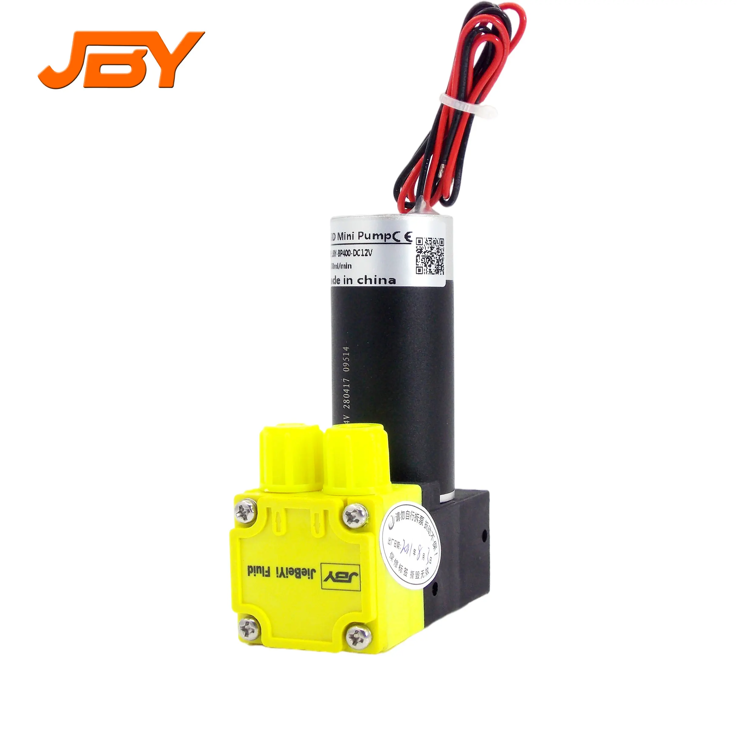
The AMT Self priming electric pumps are designed for circulating, boosting, wash down, liquid transfer and dewatering applications. The centerline discharge feature is specifically designed to prevent vapor binding and makes for convenient piping connections. All models are fitted with self-cleaning semi-open impellers. The units will self-prime to 15 feet. Mounting bases feature 7/16" mounting holes which are 6" OC (on center). Built-in carrying handles offer portability. PumpBiz also offers electric motor starters / controls.
For the Inlet & Outlet sizes refer to the dimensional outline drawing or the specific pumps detailed page. WVO, biodiesel, used in a Biodiesel Processor application where it"s pumping oil through it & small blends of methoxide are metered into the pump as it"s running.
These are some of the smaller electric AMT IPT self priming pumps, other versions in larger size and / or engine powered. AMT pumps are proudly made completely in the USA. Once primed these pumps will continue to re-prime the suction hose when started.
Norman Equipment has been a leading supplier of hydraulic equipment including hydraulic piston pumps and motors for over 70 years. Full-line authorized stocking distributor of quality hydraulic components and systems from top manufacturers renowned for performance and reliability.
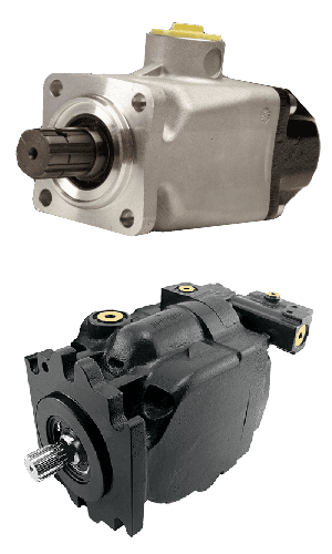
We recommend using the piston pumps in high-pressure applications. In some cases, it is more economical to run a piston pump compensated that puts out a very low output flow until needed. This lowers electric cost and pump wear that may reduce system down time.
Norman currently stocks the Parker Denison PV (PVP) units and is part of the Parker Denison Distribution Network if another unit is needed that is not in stock at Norman Equipment. Denison is one of the most recognized names in hydraulic units in the world. For many years, their products were recognized by their distinctive blue color. Today, the Denison brand is part of the Parker-Hannifin family and all pumps are painted black.
This website is using a security service to protect itself from online attacks. The action you just performed triggered the security solution. There are several actions that could trigger this block including submitting a certain word or phrase, a SQL command or malformed data.

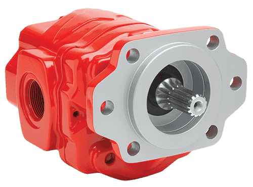
The gear pump is a PD (Positive displacement) pump. It helps to develop a flow by carrying the fluid between repeatedly enclosing interlocking gears or cogs, transferring it automatically using a cyclical pumping action. So, the Gear pump provides a smooth pulseless fluid flow of which rate depends on its gears’ rotational speed.
The gear pump uses the rotating gears or cogs’ action to move fluids. Its rotating part forms a fluid seal by the casing of the pump and creates the suction at the inlet of the gear pump. Fluid pulled into a gear pump is surrounded within the rotating gears or cogs cavities and shifted out to discharge.
External design Gear pump contains two identical and interlocking gears that are supported through separate shafts. The motor is used to drive the first gear which drives the second gear. In a few cases, electrical motors can drive both shafts that are supported with bearings on every side of the casing.When gears move out from the mesh on the pump’s inlet side, they form an extended volume, Fluid flows into the pump’s cavities and entrapped by the edges of gear while gears carry on rotating against the casing of the pump.
The fluid cannot be transferred back over the center, amongst the gears, as they got connected. Close tolerances amongst the casing and the gears let the external gear pump to extend suction over the inlet and prohibit fluid from going back from the pump’s discharge side (Though the low viscosity fluids have more tendency for fluid leakage).
The Internal Design Gear Pump works the same as of External Design Gear Pump except that it’s both interconnected gears have different sizes where one rotates inside of others. It has a larger internal gear which is called the rotor i.e. its edges projecting from the inside. The other external gear of small size mounted into the center of the rotor which is called the idler. It is designed for interconnecting with the outer rotor in a way that edges of gear engage at the one end. The bushing along with a pinion is attached to the casing of the pump which holds inner idle into its location. A crescent shape fixed divider fills the vacant place which is created by the idler’s irregular mounting position. It works like the seal amongst outlet & inlet ports.When gears move out from the mesh on the pump’s inlet side, they form an extended volume, fluid flows into the pump’s cavities, and entrapped by the edges of gear while gears carry on rotating against the partition and casing of the pump.
The gear pump has few moving parts and is very simple and compact. Its pressure power cannot be matched with reciprocating pumps or the rates of flow of the centrifugal pumps. Yet it provides higher throughputs and pressures than lobe pumps or vanes. The gear pump is specifically suitable for fluids of high viscosity and pumping oils.
From the two types of gear pump, the external design has the ability to sustain high flow rates and pressures (more than 3000psi) due to its closer tolerances and stronger shaft support. Internal design provides better suction. It is suitable for fluids of high viscosity but it provides an operating range of 1cp to more than 1,000,000cp. As output depends on the rotational speed, the gear pump is mostly used for blending and metering operations. The gear pump can also be engineered for handling the aggressive liquids. Whereas it is generally made from stainless steel or cast iron, new composites and alloys let the pump handle the corrosive fluids like sodium hypochlorite, sulphuric acid, sodium hydroxide, and ferric chloride.
The external design can be used in lifting machinery, hydraulic power, plant equipment, and vehicles. When the gear pump is driven in reverse, by using the oil which can be pumped from anywhere in the system (generally through a tandem pump within an engine), creates the hydraulic motor. It can be beneficial for providing power in those fields where the electrical system is costly, inconvenient, or bulky. For example, a tractor depends on an external design engine-driven gear pump to power its services.
The gear pump is self-priming yet it can also dry lift, though its priming features can be enhanced by wetting the gears. The gears should not run dry for a prolonged period and must be lubricated through a pumped fluid. Some designs of gear pumps can be operated in both directions (forward or reverse). Since the same gear pump can be utilized for loading and unloading the vessel, for instance.
Close tolerance amongst the casing and gear means that this pump type is vulnerable to wear especially when feeds consisting of entrained solids or the abrasive fluids are used. Though, few pump designs, specifically internal variants that let to handle the solids as well. The external design gear pump has four bearings with tight tolerances. Therefore, it is less suitable to handle abrasive fluids. The internal design gear pump is more robust and has just one bearing (maybe two) to run in a fluid. The gear pump needs to install a strainer on a suction side that can protect it from potential damages of solids.
In general, when a gear pump requires for handling abrasive solids then it’s better to choose a pump with higher capacity that can be run at low speed to avoid wear. But it must keep in mind that the gear pump’s volumetric efficiency becomes lessens at low flow rates and speeds. The gear pump must not be run beyond the recommended speed.
In applications of high temperature, it’s necessary to make sure that an operating range of temperature is compatible along with the specification of the pump. Gears and casings’ thermal expansion lessens clearances in the pump which can lead towards increased wear as well as in extreme circumstances, pump failure.
In spite of the best precautions, the bearings, casing, and gears of the pump succumb to wearing with every passing day. As there is an increase in clearances, a gradual decrease in efficiency happens along with an increase in the flow slip: pumped fluid’ leakage from the expulsion back towards a suction side. The flow slip depends on the clearance’ cube between the casing and cog edge so, practically, wear provide a small impact till a critical stage is reached after which the performance of the pump degrades rapidly.
Gear pumps continue to pump in contrary to reverse pressure then, if downstream blockage happens, it will carry on to the pressurized system till the pipework, pump, or other parts fails. Due to this reason, some gear pumps are used to equip with the relief valves. It’s advisable to use a relief valve anywhere within a system for protecting the downstream equipment.
The internal designs gear pumps that operated at less speed are considered ideal for the shear-sensitive fluids like paint, soaps, and foodstuffs. The lower clearances and higher speeds of eternal design gears make them appropriate for these kinds of applications. The internal design gear pump also prefers where hygiene conditions are more important due to its mechanical simplicity. This is a fact that it has easy to clean, strip down, and reassemble features.
Gear pumps are appropriate for pumping the fluids of high viscosity like foodstuff, oil, paints, or resins. They are used in any kind of application where the output of high pressure or accurate dosing is required. The gear pump output is not affected too much by pressure and they can be used in any type of situation where irregular supply occurs.
The gear pump helps to develop a flow by carrying the fluid between repeatedly enclosing interlocking gears or cogs, transferring it automatically to smooth pulseless flow of which rate depends on its gears’ rotational speed. Two basic design types of gear pumps are external design and internal design.
External design Gear pump contains two identical and interlocking gears that are supported through separate shafts. The Internal Design Gear Pump has two interconnected gears having different sizes where one rotates inside of others.
Gear pumps are appropriate for pumping the fluids of high viscosity like foodstuff, oil, paints, or resins. They are used in any kind of application where the output of high pressure or accurate dosing is required. The external design gear pump is used to sustain high pressure (more than 7500 psi) while the internal design gear pump provides better suction and is more suitable to fluids which are shear sensitive and of high viscosity.


 8613371530291