
priming tractor hydraulic pump free sample
Things like restrictions and blockages can impede the flow of fluid to your pump. which could contribute to poor fluid flow. Air leak in suction line. Air present in the pump at startup. Insufficient supply of oil in pump. Clogged or dirty fluid filters. Clogged inlet lines or hoses. Blocked reservoir breather vent. Low oil in the reservoir
Now that we’ve ensured that the directional control is not reversed, it’s time to check that the drive motor itself is turning in the right direction. Sometimes incorrect installation leads to mismatched pipe routings between control valves and motors, which can reverse the direction of flow. Check to see that the motor is turning the pump in the right direction and if not - look at your piping.
Check to ensure that your pump drive motor is turning over and is developing the required speed and torque. In some cases, misalignment can cause binding of the drive shaft, which can prevent the motor from turning. If this is the case, correct the misalignment and inspect the motor for damage. If required, overhaul or replace motor.
Check to ensure the pump to motor coupling is undamaged. A sheared pump coupling is an obvious cause of failure, however the location of some pumps within hydraulic systems makes this difficult to check so it may go overlooked
It is possible that the entire flow could be passing over the relief valve, preventing the pressure from developing. Check that the relief valve is adjusted properly for the pump specifications and the application.
Seized bearings, or pump shafts and other internal damage may prevent the pump from operating all together. If everything else checks out, uncouple the pump and motor and check to see that the pump shaft is able to turn. If not, overhaul or replace the pump.
If your pump is having problems developing sufficient power, following this checklist will help you to pinpoint the problem. In some cases you may find a simple solution is the answer. If your pump is exhibiting any other issues such as noise problems, heat problems or flow problems, you may need to do some more investigation to address the root cause of your pump problem. To help, we’ve created a downloadable troubleshooting guide containing more information about each of these issues. So that you can keep your system up and running and avoid unplanned downtime. Download it here.

Check that the pump shaft is rotating. Even though coupling guards and C-face mounts can make this difficult to confirm, it is important to establish if your pump shaft is rotating. If it isn’t, this could be an indication of a more severe issue, and this should be investigated immediately.
Check the oil level. This one tends to be the more obvious check, as it is often one of the only factors inspected before the pump is changed. The oil level should be three inches above the pump suction. Otherwise, a vortex can form in the reservoir, allowing air into the pump.
What does the pump sound like when it is operating normally? Vane pumps generally are quieter than piston and gear pumps. If the pump has a high-pitched whining sound, it most likely is cavitating. If it has a knocking sound, like marbles rattling around, then aeration is the likely cause.
Cavitation is the formation and collapse of air cavities in the liquid. When the pump cannot get the total volume of oil it needs, cavitation occurs. Hydraulic oil contains approximately nine percent dissolved air. When the pump does not receive adequate oil volume at its suction port, high vacuum pressure occurs.
This dissolved air is pulled out of the oil on the suction side and then collapses or implodes on the pressure side. The implosions produce a very steady, high-pitched sound. As the air bubbles collapse, the inside of the pump is damaged.
While cavitation is a devastating development, with proper preventative maintenance practices and a quality monitoring system, early detection and deterrence remain attainable goals. UE System’s UltraTrak 850S CD pump cavitation sensor is a Smart Analog Sensor designed and optimized to detect cavitation on pumps earlier by measuring the ultrasound produced as cavitation starts to develop early-onset bubbles in the pump. By continuously monitoring the impact caused by cavitation, the system provides a simple, single value to trend and alert when cavitation is occurring.
The oil viscosity is too high. Low oil temperature increases the oil viscosity, making it harder for the oil to reach the pump. Most hydraulic systems should not be started with the oil any colder than 40°F and should not be put under load until the oil is at least 70°F.
Many reservoirs do not have heaters, particularly in the South. Even when heaters are available, they are often disconnected. While the damage may not be immediate, if a pump is continually started up when the oil is too cold, the pump will fail prematurely.
The suction filter or strainer is contaminated. A strainer is typically 74 or 149 microns in size and is used to keep “large” particles out of the pump. The strainer may be located inside or outside the reservoir. Strainers located inside the reservoir are out of sight and out of mind. Many times, maintenance personnel are not even aware that there is a strainer in the reservoir.
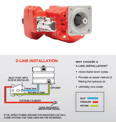
The suction strainer should be removed from the line or reservoir and cleaned a minimum of once a year. Years ago, a plant sought out help to troubleshoot a system that had already had five pumps changed within a single week. Upon closer inspection, it was discovered that the breather cap was missing, allowing dirty air to flow directly into the reservoir.
A check of the hydraulic schematic showed a strainer in the suction line inside the tank. When the strainer was removed, a shop rag was found wrapped around the screen mesh. Apparently, someone had used the rag to plug the breather cap opening, and it had then fallen into the tank. Contamination can come from a variety of different sources, so it pays to be vigilant and responsible with our practices and reliability measures.
The electric motor is driving the hydraulic pump at a speed that is higher than the pump’s rating. All pumps have a recommended maximum drive speed. If the speed is too high, a higher volume of oil will be needed at the suction port.
Due to the size of the suction port, adequate oil cannot fill the suction cavity in the pump, resulting in cavitation. Although this rarely happens, some pumps are rated at a maximum drive speed of 1,200 revolutions per minute (RPM), while others have a maximum speed of 3,600 RPM. The drive speed should be checked any time a pump is replaced with a different brand or model.
Every one of these devastating causes of cavitation threatens to cause major, irreversible damage to your equipment. Therefore, it’s not only critical to have proper, proactive practices in place, but also a monitoring system that can continuously protect your valuable assets, such as UE System’s UltraTrak 850S CD pump cavitation senor. These sensors regularly monitor the health of your pumps and alert you immediately if cavitation symptoms are present, allowing you to take corrective action before it’s too late.
Aeration is sometimes known as pseudo cavitation because air is entering the pump suction cavity. However, the causes of aeration are entirely different than that of cavitation. While cavitation pulls air out of the oil, aeration is the result of outside air entering the pump’s suction line.
Several factors can cause aeration, including an air leak in the suction line. This could be in the form of a loose connection, a cracked line, or an improper fitting seal. One method of finding the leak is to squirt oil around the suction line fittings. The fluid will be momentarily drawn into the suction line, and the knocking sound inside the pump will stop for a short period of time once the airflow path is found.
A bad shaft seal can also cause aeration if the system is supplied by one or more fixed displacement pumps. Oil that bypasses inside a fixed displacement pump is ported back to the suction port. If the shaft seal is worn or damaged, air can flow through the seal and into the pump’s suction cavity.
As mentioned previously, if the oil level is too low, oil can enter the suction line and flow into the pump. Therefore, always check the oil level with all cylinders in the retracted position.
If a new pump is installed and pressure will not build, the shaft may be rotating in the wrong direction. Some gear pumps can be rotated in either direction, but most have an arrow on the housing indicating the direction of rotation, as depicted in Figure 2.
Pump rotation should always be viewed from the shaft end. If the pump is rotated in the wrong direction, adequate fluid will not fill the suction port due to the pump’s internal design.
A fixed displacement pump delivers a constant volume of oil for a given shaft speed. A relief valve must be included downstream of the pump to limit the maximum pressure in the system.
After the visual and sound checks are made, the next step is to determine whether you have a volume or pressure problem. If the pressure will not build to the desired level, isolate the pump and relief valve from the system. This can be done by closing a valve, plugging the line downstream, or blocking the relief valve. If the pressure builds when this is done, there is a component downstream of the isolation point that is bypassing. If the pressure does not build up, the pump or relief valve is bad.
If the system is operating at a slower speed, a volume problem exists. Pumps wear over time, which results in less oil being delivered. While a flow meter can be installed in the pump’s outlet line, this is not always practical, as the proper fittings and adapters may not be available. To determine if the pump is badly worn and bypassing, first check the current to the electric motor. If possible, this test should be made when the pump is new to establish a reference. Electric motor horsepower is relative to the hydraulic horsepower required by the system.
For example, if a 50-GPM pump is used and the maximum pressure is 1,500 psi, a 50-hp motor will be required. If the pump is delivering less oil than when it was new, the current to drive the pump will drop. A 230-volt, 50-hp motor has an average full load rating of 130 amps. If the amperage is considerably lower, the pump is most likely bypassing and should be changed.
Figure 4.To isolate a fixed displacement pump and relief valve from the system, close a valve or plug the line downstream (left). If pressure builds, a component downstream of the isolation point is bypassing (right).
The most common type of variable displacement pump is the pressure-compensating design. The compensator setting limits the maximum pressure at the pump’s outlet port. The pump should be isolated as described for the fixed displacement pump.
If pressure does not build up, the relief valve or pump compensator may be bad. Prior to checking either component, perform the necessary lockout procedures and verify that the pressure at the outlet port is zero psi. The relief valve and compensator can then be taken apart and checked for contamination, wear, and broken springs.
Install a flow meter in the case drain line and check the flow rate. Most variable displacement pumps bypass one to three percent of the maximum pump volume through the case drain line. If the flow rate reaches 10 percent, the pump should be changed. Permanently installing a flow meter in the case drain line is an excellent reliability and troubleshooting tool.
Ensure the compensator is 200 psi above the maximum load pressure. If set too low, the compensator spool will shift and start reducing the pump volume when the system is calling for maximum volume.
Performing these recommended tests should help you make good decisions about the condition of your pumps or the cause of pump failures. If you change a pump, have a reason for changing it. Don’t just do it because you have a spare one in stock.
Conduct a reliability assessment on each of your hydraulic systems so when an issue occurs, you will have current pressure and temperature readings to consult.
Al Smiley is the president of GPM Hydraulic Consulting Inc., located in Monroe, Georgia. Since 1994, GPM has provided hydraulic training, consulting and reliability assessments to companies in t...
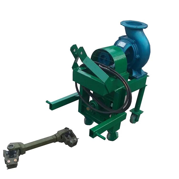
The unit replaces existing hand primers and uses tractor or auxiliary hydraulics to prime the pump. "Oftentimes, there are small air leaks in the system that are tough to overcome when hand priming," explains Don Mueller, marketing director for the company.
The primer can be used with most water and manure pumps, and attaches in place of the hand primer. The hydraulic unit retrofits to replace most hand primers. It can also be used as a small pump with an approximate 75 gpm output.
Hydraulic Primer For Manure, Water Pumps MANURE HANDLING Equipment 8-3-4 Say goodbye to the sweat and agony of hand priming centrifugal manure and water pumps with the just-introduced hydraulic primer from Moulton Industries, Somerset, Wis.The unit replaces existing hand primers and uses tractor or auxiliary hydraulics to prime the pump. "Oftentimes, there are small air leaks in the system that are tough to overcome when hand priming," explains Don Mueller, marketing director for the company."Our new hydraulic primer overcomes the small air leaks, allowing you to prime even the most stubborn pump in a minute or less!"The primer can be used with most water and manure pumps, and attaches in place of the hand primer. The hydraulic unit retrofits to replace most hand primers. It can also be used as a small pump with an approximate 75 gpm output.Sells for $550.For more information, contact: FARM SHOW Followup, Moulton Irrigation Industries, Inc., Somerset, Wis. 54025 (ph 715 247-3321).

“We have a hydraulic system that operates two cylinders. The maintenance staff recently reported that the pump (piston-type) had failed – for reasons unknown at this time. The tank, valves and cylinders were cleaned and a replacement pump installed. The new pump is delivering a maximum pressure of 1,000 PSI and appears to be creating heat. Can you suggest some tips to find a solution to this problem?”
In any troubleshooting situation, no matter how simple or complex the hydraulic system, always start with the basics. This ensures that the obvious is never overlooked. In order for the ‘obvious’ to be obvious, the fundamental laws of hydraulics must be kept in mind:
We know that a hydraulic pump can only produce flow (pressure is created by resistance to flow). It follows that if the pump can’t get oil it can’t produce flow. So check that the reservoir is filled to the correct level, the breather is not clogged, the suction strainer or filter (if fitted) is not clogged, the pump intake isolation valve is fully open and the pump intake line is otherwise unrestricted.
If the pump is producing flow, then an absence of pressure indicates an absence of resistance to flow. Knowing this, and that fluid under pressure always takes the path of least resistance, the task now is to find the point at which pump flow is escaping from the circuit. If you’re skilled in reading and interpreting hydraulic symbols, the system’s schematic diagram (if available) can be useful in identifying possible locations.
Because heat is generated when there is a pressure drop without useful work, using an infrared thermometer to check the temperature of individual components will quickly lead us to the hottest part of the system – and the probable location of the internal leakage. Note that in a properly functioning system fitted with a piston pump, it is not unusual for the pump case to be the hottest part of the circuit. These checks should have taken less than 10 minutes. If nothing conclusive was revealed, I would continue the process of elimination using a flow-tester to conduct a direct pump test.
Bottom line: not having a solid understanding of the fundamental laws of hydraulics can result in costly troubleshooting mistakes. And to discover six other costly mistakes you want to be sure to avoid with your hydraulic equipment, get “Six Costly Mistakes Most Hydraulics Users Make… And How You Can Avoid Them!” available for FREE download here.

A gear pump is a type of positive displacement (PD) pump. It moves a fluid by repeatedly enclosing a fixed volume using interlocking cogs or gears, transferring it mechanically using a cyclic pumping action. It delivers a smooth pulse-free flow proportional to the rotational speed of its gears.
Gear pumps use the actions of rotating cogs or gears to transfer fluids. The rotating element develops a liquid seal with the pump casing and creates suction at the pump inlet. Fluid, drawn into the pump, is enclosed within the cavities of its rotating gears and transferred to the discharge. There are two basic designs of gear pump: external and internal(Figure 1).
An external gear pump consists of two identical, interlocking gears supported by separate shafts. Generally, one gear is driven by a motor and this drives the other gear (the idler). In some cases, both shafts may be driven by motors. The shafts are supported by bearings on each side of the casing.
As the gears come out of mesh on the inlet side of the pump, they create an expanded volume. Liquid flows into the cavities and is trapped by the gear teeth as the gears continue to rotate against the pump casing.
No fluid is transferred back through the centre, between the gears, because they are interlocked. Close tolerances between the gears and the casing allow the pump to develop suction at the inlet and prevent fluid from leaking back from the discharge side (although leakage is more likely with low viscosity liquids).
An internal gear pump operates on the same principle but the two interlocking gears are of different sizes with one rotating inside the other. The larger gear (the rotor) is an internal gear i.e. it has the teeth projecting on the inside. Within this is a smaller external gear (the idler –only the rotor is driven) mounted off-centre. This is designed to interlock with the rotor such that the gear teeth engage at one point. A pinion and bushing attached to the pump casing holds the idler in position. A fixed crescent-shaped partition or spacer fills the void created by the off-centre mounting position of the idler and acts as a seal between the inlet and outlet ports.
As the gears come out of mesh on the inlet side of the pump, they create an expanded volume. Liquid flows into the cavities and is trapped by the gear teeth as the gears continue to rotate against the pump casing and partition.
Gear pumps are compact and simple with a limited number of moving parts. They are unable to match the pressure generated by reciprocating pumps or the flow rates of centrifugal pumps but offer higher pressures and throughputs than vane or lobe pumps. Gear pumps are particularly suited for pumping oils and other high viscosity fluids.
Of the two designs, external gear pumps are capable of sustaining higher pressures (up to 3000 psi) and flow rates because of the more rigid shaft support and closer tolerances. Internal gear pumps have better suction capabilities and are suited to high viscosity fluids, although they have a useful operating range from 1cP to over 1,000,000cP. Since output is directly proportional to rotational speed, gear pumps are commonly used for metering and blending operations. Gear pumps can be engineered to handle aggressive liquids. While they are commonly made from cast iron or stainless steel, new alloys and composites allow the pumps to handle corrosive liquids such as sulphuric acid, sodium hypochlorite, ferric chloride and sodium hydroxide.
External gear pumps can also be used in hydraulic power applications, typically in vehicles, lifting machinery and mobile plant equipment. Driving a gear pump in reverse, using oil pumped from elsewhere in a system (normally by a tandem pump in the engine), creates a hydraulic motor. This is particularly useful to provide power in areas where electrical equipment is bulky, costly or inconvenient. Tractors, for example, rely on engine-driven external gear pumps to power their services.
Gear pumps are self-priming and can dry-lift although their priming characteristics improve if the gears are wetted. The gears need to be lubricated by the pumped fluid and should not be run dry for prolonged periods. Some gear pump designs can be run in either direction so the same pump can be used to load and unload a vessel, for example.
The close tolerances between the gears and casing mean that these types of pump are susceptible to wear particularly when used with abrasive fluids or feeds containing entrained solids. However, some designs of gear pumps, particularly internal variants, allow the handling of solids. External gear pumps have four bearings in the pumped medium, and tight tolerances, so are less suited to handling abrasive fluids. Internal gear pumps are more robust having only one bearing (sometimes two) running in the fluid. A gear pump should always have a strainer installed on the suction side to protect it from large, potentially damaging, solids.
Generally, if the pump is expected to handle abrasive solids it is advisable to select a pump with a higher capacity so it can be operated at lower speeds to reduce wear. However, it should be borne in mind that the volumetric efficiency of a gear pump is reduced at lower speeds and flow rates. A gear pump should not be operated too far from its recommended speed.
For high temperature applications, it is important to ensure that the operating temperature range is compatible with the pump specification. Thermal expansion of the casing and gears reduces clearances within a pump and this can also lead to increased wear, and in extreme cases, pump failure.
Despite the best precautions, gear pumps generally succumb to wear of the gears, casing and bearings over time. As clearances increase, there is a gradual reduction in efficiency and increase in flow slip: leakage of the pumped fluid from the discharge back to the suction side. Flow slip is proportional to the cube of the clearance between the cog teeth and casing so, in practice, wear has a small effect until a critical point is reached, from which performance degrades rapidly.
Gear pumps continue to pump against a back pressure and, if subjected to a downstream blockage will continue to pressurise the system until the pump, pipework or other equipment fails. Although most gear pumps are equipped with relief valves for this reason, it is always advisable to fit relief valves elsewhere in the system to protect downstream equipment.
Internal gear pumps, operating at low speed, are generally preferred for shear-sensitive liquids such as foodstuffs, paint and soaps. The higher speeds and lower clearances of external gear designs make them unsuitable for these applications. Internal gear pumps are also preferred when hygiene is important because of their mechanical simplicity and the fact that they are easy to strip down, clean and reassemble.
Gear pumps are commonly used for pumping high viscosity fluids such as oil, paints, resins or foodstuffs. They are preferred in any application where accurate dosing or high pressure output is required. The output of a gear pump is not greatly affected by pressure so they also tend to be preferred in any situation where the supply is irregular.
A gear pump moves a fluid by repeatedly enclosing a fixed volume within interlocking cogs or gears, transferring it mechanically to deliver a smooth pulse-free flow proportional to the rotational speed of its gears. There are two basic types: external and internal. An external gear pump consists of two identical, interlocking gears supported by separate shafts. An internal gear pump has two interlocking gears of different sizes with one rotating inside the other.
Gear pumps are commonly used for pumping high viscosity fluids such as oil, paints, resins or foodstuffs. They are also preferred in applications where accurate dosing or high pressure output is required. External gear pumps are capable of sustaining higher pressures (up to 7500 psi) whereas internal gear pumps have better suction capabilities and are more suited to high viscosity and shear-sensitive fluids.
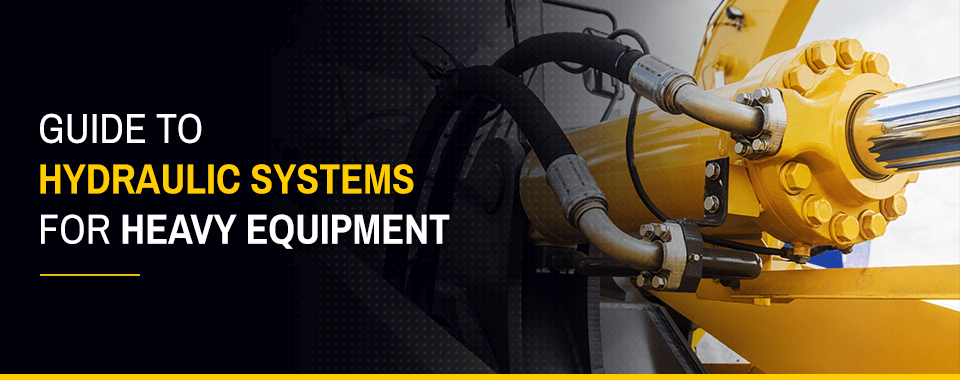
Without hydraulics, modern construction equipment wouldn’t operate as effectively as it does. Because of this fluid-based system, heavy equipment can use small operator motions to create large movements in attachments and things they hold. Knowing when to repair the hydraulics of heavy equipment requires an understanding of the system. This guide provides important information you need to know about hydraulic systems used for heavy equipment.
The definition of a hydraulic system is an operation that uses pressurized fluid to power motion. The pressure of the fluid multiplies pressure put on it to increase the force at the output. A hydraulic system uses this fluid in cylinders or hydraulic power units to do work such as stop a vehicle through its brakes, lift a crane and its load or move a bucket on a loader.
Within a hydraulic system, there are components that put the incompressible fluid under pressure. Because the hydraulic oil does not press into a smaller space, the force applied to it gets transferred to the other end of the area where the oil is. The pressure exerted from the oil moves a large piston that can work alone or with additional cylinders to move things requiring extra force.
When equipping a device with a hydraulic system, you can increase the amount of work the system can do without increasing the effort you put into it. Applied to construction equipment, hydraulic power systems allow a small joystick movement to lift a tractor bucket filled with weighty rubble.
Such an operation would not be possible with humans using their muscles and shovels to lift the same amount of debris. For instance, a steam-driven predecessor of today’s hydraulic-powered construction equipment could move the same amount of substance in a day that two men equipped with a wheelbarrow could do in two weeks.
The improvements made to hydraulic systems have only increased their ability to make today’s equipment capable of the heavy lifting on construction sites that requires long-lasting reliability, power and control.
Power density: The output of hydraulics is many times greater than the force put into the system, reaching close to 7,000 pounds per square inch in some pieces of heavy construction equipment.
Hydraulic systems operate with one of two methods: cylinders or hydraulic power units. Cylinders are the original components used to multiply force with hydraulic fluid. However, advances in engineering now allow improved operations from larger hydraulic power units that increase the system’s work capability.
When using cylinders, hydraulic systems have a smaller and a larger cylinder. The smaller one has a piston for work put into the system. The piston presses down on hydraulic fluid in the small cylinder and flows into the bottom of the larger cylinder. The large cylinder also has a piston that moves based on the force of the oil.
The other type of system used is a hydraulic power unit that increases the capabilities of the system by using a pump and pressurized fluid to replace the small cylinder.
While the distance the small piston travels determines the output in a system that uses cylinders, those that have hydraulic power units do not have the limitation of physical distance. By raising the pressure of the fluid, the need for travel distance disappears, allowing for far higher output forces than with a cylinder system. This type of system is often used on construction equipment to achieve massive amounts of work and lifting capabilities.
The use of small and large cylinders and pistons works in some tiny devices, but the heavy loads and large movements required of construction equipment need more robust hydraulic solutions. For these more extensive devices, hydraulic power units replace cylinders for higher power output.
Because hydraulic power units (HPUs) bring in more fluid from a pump at higher pressures, they can create a force that equals a greater travel distance needed by a small piston. Since these HPUs do not have the physical size of a small cylinder to limit them, they can create far more force for the output than two-cylinder systems can.
An HPU contains all the components needed to operate the hydraulic system — including a pump, motor and fluid reservoir — in a self-contained area. The pump and its motor generate a small amount of pressure needed to move the system. When the hydraulic system starts, the pump delivers oil into the accumulator. Once the oil in the accumulator reaches the necessary pressure, the bigger piston moves, and a valve allows pressure to drop as the fluid returns to the reservoir.
Some hydraulic systems use two-stage pumps that permit faster pushing and pulling of a hydraulically operated force by shifting between high pressure and low flow rate and low pressure and high flow rate of the oil. A large reservoir is a requirement for many HPUs on earthmoving equipment. For some pieces of equipment that have multiple cylinders, the reservoirs can store dozens of gallons of fluid.
The hydraulic systems on construction equipment can operate various components. For example, the tracks on tracked backhoes have hydraulic drivers. Loaders often have a pair of pistons to move the bucket vertically, a couple to rotate the bucket to turn out contents and a set to open the bucket’s sides. Dump trucks have a comparatively simple operation, only requiring one or two cylinders to lift the bed.
Cranes also use hydraulics in many ways. For cranes that have outriggers to lift the entire system, hydraulic systems provide the power to hoist the multi-ton vehicle vertically. To turn the crane’s load on a boom, a hydraulic system moves the Rotex gear. The boom also telescopes in or out thanks to the motions of hydraulics. The operator’s controls connect to the hydraulic hoses in a crane and other similarly operated construction equipment.
Using the controls in the operator’s cab changes the flow of hydraulic fluid in the system, allowing for parts of the equipment to move. The fluid routing happens at the spool valves, which link oil lines to the pump and each other. These valves change the direction of the fluid, which moves the hydraulic force to the parts of the equipment where the operator needs it to go.
Because the hydraulic systems in heavy equipment allow these pieces to perform vital work, problems with the hydraulic power unit’s motor, pump or reservoir can hamper productivity on a job site. In these situations, it’s helpful to identify the symptoms of the problem and get the equipment to a service shop for repairs to minimize downtime.
While reliable, the hydraulic system for earthmoving equipment and other similar vehicles can have problems. Major symptoms of hydraulic system issues include the following:
Noisy operation means there’s excessive noise coming from some part of the equipment. Listen carefully for the source of the sound because this can help a certified technician identify potential problems. For instance, a noisy pump could indicate air in the hydraulic fluid, a worn pump or misaligned couplings.
Noise coming from the pump’s motor could also be a sign of misaligned couplings or wear in the pump’s engine. When you hear extra noise coming from the relief valve, the valve may not have the correct setting or a poppet on it may have worn.
Be cautious about making a diagnosis of your hydraulic system only from the sounds and their locations. A certified technician has the tools and tests to determine the exact cause of the noise and provide a repair for it.
Problems with hydraulic fluid flow fall into three categories – too much flow, not enough flow or no current flow. Because these groupings cover a wide range of causes, a certified technician may need to conduct additional diagnostic tests or look for other factors to find the exact cause.
Many of these problems will require service to the pump or replacement parts in the hydraulic pump. The certified technician may also need to make repairs or part replacements based on the wear sustained by your equipment’s hydraulic system.
Abnormal movement of a hydraulic system can lead to dangerous situations on a construction site. Hydraulically operated components must move as expected. Erratic, slow, inconsistent or limited movement all indicate serious problems that need immediate repairs. These faulty movements may happen in conjunction with other issues, such as oil flow problems or noisy operation. For example, a lack of hydraulic fluid flowing through the pump may completely restrict movement. Any air in the oil may cause both noisy use and erratic operation.
Incorrect pressure in a hydraulic system closely mirrors faulty operation. If your equipment shows faulty operation, a technician may need to look at the pressure of the fluid and determine the cause of the pressure problem first. For instance, air in the oil may cause both erratic pressure and erratic operation of the hydraulic mechanism. Low pressure could happen from a damaged pump or pressure reduction valve and cause the system to operate slowly.
A hydraulic system may overheat when the fluid overheats. Whichever component of the system runs hot can provide a clue to the source of the excess heat. For instance, if the pump or motor run hot, the system may have too high of a load put on it, the engine may have damage or the relief valve may be set too high.
As with other hydraulic system problems, an expert must conduct a thorough investigation of the entire system to identify the sources of any issues. When looking for an expert, choose a certified technician who has the replacement parts for your equipment’s brand on hand. This combination ensures your heavy equipment will be repaired correctly and as quickly as possible.
If your hydraulic system needs service or replacement parts, connect with us at Prime Source. Our shop service capabilities range from offering replacement parts for all makes of heavy equipment to providing repairs for hydraulic systems. Our certified technicians can inspect your equipment’s hydraulic system as a whole and make any necessary repairs or part replacements.
We aim to give our customers the highest caliber of service possible for their heavy equipment. Our expertise in multiple equipment brands sets us apart from the rest, and our customers trust us for our outstanding service and unparalleled range of parts. Learn more about our shop service capabilities today, whether you own a single tractor or a fleet of heavy equipment.

When it comes to operating heavy machinery and equipment, a hydraulic system likely does the heavy lifting. These powerful pieces of equipment are capable of moving impressive weights and are behind some of the most vital tasks of many businesses. With all the work they do, proper hydraulic system care is critical. Without it, you risk damaging the components, losing efficiency and injuring workers by creating safety hazards.
Many maintenance tasks need to be done regularly, so it helps to keep a list handy. We"ve compiled a hydraulic system maintenance checklist, so you can ensure your system stays clean and healthy.
A hydraulic system is a critical component of most heavy machinery. The fluid power a hydraulic system generates enables the force needed to lift and move heavy parts.
Hydraulic systems themselves feature numerous intricate components that must operate efficiently for the system to function. Keeping each assembly in working order requires a regular maintenance routine.
Your employees are the heart and soul of your organization — ensuring their safety allows you to continue doing what you do. Working around hydraulic equipment is dangerous, especially when the equipment malfunctions or breaks down. Instituting a regular maintenance routine will help you notice and repair potentially hazardous issues to minimize the chances of a harmful incident occurring.
Time is money, so you do everything you can to keep your crew on schedule. Regular equipment maintenance is a critical aspect of workplace efficiency, as servicing your equipment will help prevent breakdowns and injuries that could halt your operations. Rather than falling behind due to unforeseen incidents, work regular maintenance into your schedule to maximize uptime. The comparatively small amount of time you dedicate to hydraulic equipment maintenance will increase your organization"s productivity in the long run.
Your organization spent a lot of money purchasing hydraulic equipment, so it is wise to preserve that investment through consistent maintenance. A breakdown could cause you to spend even more money repairing or replacing those resources. Maintenance technicians clear the clogs and corrosion that could damage your system"s critical components. By investing a small amount in hydraulic servicing, you will save your business from the high costs of repairing components, replacing your entire system or covering employee medical bills.
Check your hydraulic oil on a consistent schedule — it needs to remain clean and free of any contaminants. You should empty and replace the hydraulic oil after every 1,000 hours of work or per the manufacturer"s instructions.
Read the manufacturer specifications to confirm how often you should change the fluid and other factors of hydraulic fluid care. It is essential to use the same type of hydraulic fluid every time you top off your levels. If possible, use the same brand each time as well.
Filters take on the task of removing even the most minuscule particles that could clog your hydraulic system. However, the process of keeping particulates out of the system causes the filters themselves to become clogged over time. Your filters will lose efficacy as they accumulate pollutants, so replace them often. If applicable, make sure to clean the filter bowl as well.
Visually inspect the rod for wear, such as corrosion and pitting. These issues can lead to moisture within the fluid, which compounds and can cause many problems for your hydraulic system, like increased wear and inadequate lubrication.
For optimal functioning, you must watch your fluid levels, adding to them as needed. Too little hydraulic fluid can damage your pumps. Just like when replacing contaminated oil, be sure to follow the specifications given by the manufacturer and take care to avoid mixing oils.
Breathers must be kept clean or risk contaminating the hydraulic system. Clean the breather regularly and inspect it for holes or tears. Different types of breathers may have additional requirements, so check the manufacturer"s instructions. Spring types, for instance, may need to be replaced annually to avoid tension loss that allows contaminants. Others can have indicators that tell you when to replace filters or caps. Be aware of any additional steps such as these.
As with any maintenance task, it"s important to approach it the right way. Here are some hydraulic system troubleshooting tips that can make the process easier and faster for your employees:
Safety first:Always remember how much power a hydraulic system is capable of. Only allow skilled, trained technicians to perform maintenance on them to avoid injury or damage.
York Precision Machining & Hydraulics is leading the way in precision fluid power components and systems. York Precision is home to the renowned Bear-Loc® and Bear-Loc® Hydraulic Locking Actuator, the most reliable locking solution available. More information about Bear-Loc and York Precision products and capabilities is available here.
Proper hydraulic maintenance and a quality hydraulic locking actuator can help protect the longevity of your system and the safety of your employees. For more information about hydraulic systems and how Bear-Loc® can improve yours, reach out to a representative today.
When a hydraulic system fails, finding the source of the problem can be a challenge. Though hydraulic systems primarily consist of a sump, motor, pump, valves, actuators and hydraulic fluid, any of these parts could be the source of failure. That"s not to mention the additional potential for failure through human error and faulty maintenance practices. If your system fails, you need to know why it fails, how to find the failure and how to keep it running smoothly in the future, all while keeping personnel safe.
It"s often easy to tell when a hydraulic system fails — symptoms can include high temperatures, low pressure readings and slow or erratic operation are glaring problems. But what are the most common causes of hydraulic systems failures? We can trace most hydraulic issues back to a few common causes, listed below.
Air and water contamination are the leading causes of hydraulic failure, accounting for 80 to 90% of hydraulic failures. Faulty pumps, system breaches or temperature issues often cause both types of contamination.
Air contamination is the entrance of air into a hydraulic system and consists of two types — aeration and cavitation. Both can cause severe damage to the hydraulic system over time by wearing down the pump and surrounding components, contaminating hydraulic fluids and even overheating the system. Although we are not pump manufacturers, we know it is essential to be aware of these types of contamination and how to identify their symptoms.
Cavitation:Hydraulic oil consists of about 9% dissolved air, which the pump can pull out and implode, causing pump problems and damage to the pump and to other components in a hydraulic system over time. You can identify this problem if your hydraulic pump is making a whining noise.
Aeration:Aeration occurs when air enters the pump cavity from an outside source. Usually, loose connections or leaks in the system cause this issue. Aeration also creates a sound when the pump is running, which sounds like knocking.
Water contamination is also a common problem in hydraulic systems, often caused by system leaks or condensation due to temperature changes. Water can degrade hydraulic components over time through oxidation and freeze damage. A milky appearance in hydraulic fluid can help you identify water contamination.
Fluid oxidization: Extreme heat can cause hydraulic fluid to oxidize and thicken. This fluid thickening can cause buildups in the system that restrict flow, but can also further reduce the ability of the system to dissipate heat.
Fluid thickening:Low temperatures increase the viscosity of hydraulic oil, making it harder for the oil to reach the pump. Putting systems under load before the oil reaches 70 degrees or more can damage the system through cavitation.
Fluid levels and quality can affect hydraulic system performance. Low fluid levels and inappropriate filtration can result in air contamination, while fluid contamination can cause temperature problems. Leaks can further exacerbate both issues.
Using the correct type of fluid is also essential, as certain hydraulic oils are compatible with specific applications. There are even oil options that offer higher resistance to temperature-related problems. Some oils even offer anti-wear and anti-foam additives to help prevent against wear and air contamination, respectively.
Human error is the base cause of many hydraulic system problems. Some of the most common errors that may result in your hydraulic pump not building pressure include the following.
Faulty installations: Improper installation of any component in a hydraulic system can result in severe errors. For example, the pump shaft may be rotating in the wrong direction, negatively affecting pressure buildup, or pipes may be incorrectly fitted, resulting in leaks.
Incompatible parts: An inexperienced installer may put mismatched components together, resulting in functional failures. For example, a pump may have a motor that runs beyond its maximum drive speed.
Improper maintenance or usage:Using systems outside their operational capabilities or failing to perform regular maintenance are some of the most common causes of hydraulic system damage, but are easy to rectify through updated maintenance policies and training.
The sources of system failures can be tricky to identify, but some hydraulic troubleshooting steps can help narrow down the options. So how do you troubleshoot a hydraulic system? Here are some of the fundamentals.
Check the pump: Take the pump assembly apart and assess all parts to ensure that they are functional and installed correctly. The most common problem areas include the pump shaft, coupling and filter.
Check the fluids:Check the level, color and viscosity of the hydraulic oil to ensure it meets specifications and has not become contaminated. Low hydraulic fluid symptoms include pressure or power loss. When in doubt, drain and replace the fluids.
Check the seals: Look for evidence of any fluid leakage around your hydraulic system"s seals, especially the shaft seal. Leakage can indicate worn-out or blown seals that can cause malfunctions with pumps, motors and control valves.
Check the filters: Ensure filters are clear of plugs and blockages. Common clogged hydraulic filter symptoms include sluggish operation and noisy operation.
Hydraulic system issues are inevitable at some point. However, simple steps can help you avoid these issues and increase the longevity of your hydraulic system. On top of effective troubleshooting, you can prevent hydraulic system failure by taking the following steps.
Follow specifications: We can trace the most common hydraulic system issues back to fundamental system problems like incompatible or improperly installed parts. For this reason, it"s essential to always double-check specifications to ensure your purchased parts can work together seamlessly.
On top of these steps, look into hydraulic system products that are specifically designed to help prevent failures. One such product is Bear-Loc® by York Precision. This innovative locking actuator is a safe, reliable feature for hydraulic components, automatically locking when sleeve pressure is relieved, preventing movement if a hydraulic system fails. This way, your can protect your personnel from injuries related to hydraulic failures. Even better, York Precision offers in-house design, engineering expertise and machining and manufacturing capabilities to produce a hydraulic locking device that meets your exact specifications.
Regularly review hydraulic system maintenance, always following manufacturer recommendations and industry best practices. Also, consider the storage condition, external influences, working pressure and usage frequency of your system to tailor your maintenance schedule and procedures.
Daily tasks:Take care of a few simple daily checks to avoid issues. For example, personnel should check the oil levels, hoses and connections and listen to the pump for abnormal sounds.
Be mindful of location:Do not stand at endpoints while working on hydraulic systems. This safety measure can help prevent loss of limb and life, as there is a lot of pressure built up in these areas that can release and result in life-threatening situations.
The best safety measures, however, are to perform excellent maintenance and use high-quality parts. If you"re looking for a quality hydraulic component manufacturer, York Precision Machining & Hydraulics can help.

A hydraulic pump converts mechanical energy into fluid power. It"s used in hydraulic systems to perform work, such as lifting heavy loads in excavators or jacks to being used in hydraulic splitters. This article focuses on how hydraulic pumps operate, different types of hydraulic pumps, and their applications.
A hydraulic pump operates on positive displacement, where a confined fluid is subjected to pressure using a reciprocating or rotary action. The pump"s driving force is supplied by a prime mover, such as an electric motor, internal combustion engine, human labor (Figure 1), or compressed air (Figure 2), which drives the impeller, gear (Figure 3), or vane to create a flow of fluid within the pump"s housing.
A hydraulic pump’s mechanical action creates a vacuum at the pump’s inlet, which allows atmospheric pressure to force fluid into the pump. The drawn in fluid creates a vacuum at the inlet chamber, which allows the fluid to then be forced towards the outlet at a high pressure.
Vane pump:Vanes are pushed outwards by centrifugal force and pushed back into the rotor as they move past the pump inlet and outlet, generating fluid flow and pressure.
Piston pump:A piston is moved back and forth within a cylinder, creating chambers of varying size that draw in and compress fluid, generating fluid flow and pressure.
A hydraulic pump"s performance is determined by the size and shape of the pump"s internal chambers, the speed at which the pump operates, and the power supplied to the pump. Hydraulic pumps use an incompressible fluid, usually petroleum oil or a food-safe alternative, as the working fluid. The fluid must have lubrication properties and be able to operate at high temperatures. The type of fluid used may depend on safety requirements, such as fire resistance or food preparation.
Air hydraulic pump:These pumps have a compact design and do not require an external power source. However, a reliable source of compressed air is necessary and is limited by the supply pressure of compressed air.
Electric hydraulic pump:They have a reliable and efficient power source and can be easily integrated into existing systems. However, these pumps require a constant power source, may be affected by power outages, and require additional electrical safety measures. Also, they have a higher upfront cost than other pump types.
Gas-powered hydraulic pump:Gas-powered pumps are portable hydraulic pumps which are easy to use in outdoor and remote environments. However, they are limited by fuel supply, have higher emissions compared to other hydraulic pumps, and the fuel systems require regular maintenance.
Manual hydraulic pump:They are easy to transport and do not require a power source. However, they are limited by the operator’s physical ability, have a lower flow rate than other hydraulic pump types, and may require extra time to complete tasks.
Hydraulic hand pump:Hydraulic hand pumps are suitable for small-scale, and low-pressure applications and typically cost less than hydraulic foot pumps.
Hydraulic foot pump:Hydraulic foot pumps are suitable for heavy-duty and high-pressure applications and require less effort than hydraulic hand pumps.
Hydraulic pumps can be single-acting or double-acting. Single-acting pumps have a single port that hydraulic fluid enters to extend the pump’s cylinder. Double-acting pumps have two ports, one for extending the cylinder and one for retracting the cylinder.
Single-acting:With single-acting hydraulic pumps, the cylinder extends when hydraulic fluid enters it. The cylinder will retract with a spring, with gravity, or from the load.
Double-acting:With double-acting hydraulic pumps, the cylinder retracts when hydraulic fluid enters the top port. The cylinder goes back to its starting position.
Single-acting:Single-acting hydraulic pumps are suitable for simple applications that only need linear movement in one direction. For example, such as lifting an object or pressing a load.
Double-acting:Double-acting hydraulic pumps are for applications that need precise linear movement in two directions, such as elevators and forklifts.
Pressure:Hydraulic gear pumps and hydraulic vane pumps are suitable for low-pressure applications, and hydraulic piston pumps are suitable for high-pressure applications.
Cost:Gear pumps are the least expensive to purchase and maintain, whereas piston pumps are the most expensive. Vane pumps land somewhere between the other two in cost.
Efficiency:Gear pumps are the least efficient. They typically have 80% efficiency, meaning 10 mechanical horsepower turns into 8 hydraulic horsepower. Vane pumps are more efficient than gear pumps, and piston pumps are the most efficient with up to 95% efficiency.
Automotive industry:In the automotive industry, hydraulic pumps are combined with jacks and engine hoists for lifting vehicles, platforms, heavy loads, and pulling engines.
Process and manufacturing:Heavy-duty hydraulic pumps are used for driving and tapping applications, turning heavy valves, tightening, and expanding applications.
Despite the different pump mechanism types in hydraulic pumps, they are categorized based on size (pressure output) and driving force (manual, air, electric, and fuel-powered). There are several parameters to consider while selecting the right hydraulic pump for an application. The most important parameters are described below:
Speed of operation: If it is a manual hydraulic pump, should it be a single-speed or double-speed? How much volume of fluid per handle stroke? When using a powered hydraulic pump, how much volume per minute? Air, gas, and electric-powered hydraulic pumps are useful for high-volume flows.
Portability: Manual hand hydraulic pumps are usually portable but with lower output, while fuel power has high-output pressure but stationary for remote operations in places without electricity. Electric hydraulic pumps can be both mobile and stationary, as well as air hydraulic pumps. Air hydraulic pumps require compressed air at the operation site.
Operating temperature: The application operating temperature can affect the size of the oil reservoir needed, the type of fluid, and the materials used for the pump components. The oil is the operating fluid but also serves as a cooling liquid in heavy-duty hydraulic pumps.
Operating noise: Consider if the environment has a noise requirement. A hydraulic pump with a fuel engine will generate a higher noise than an electric hydraulic pump of the same size.
Spark-free: Should the hydraulic pump be spark-free due to a possible explosive environment? Remember, most operating fluids are derivatives of petroleum oil, but there are spark-free options.
A hydraulic pump transforms mechanical energy into fluid energy. A relatively low amount of input power can turn into a large amount of output power for lifting heavy loads.
A hydraulic pump works by using mechanical energy to pressurize fluid in a closed system. This pressurized fluid is then used to drive machinery such as excavators, presses, and lifts.
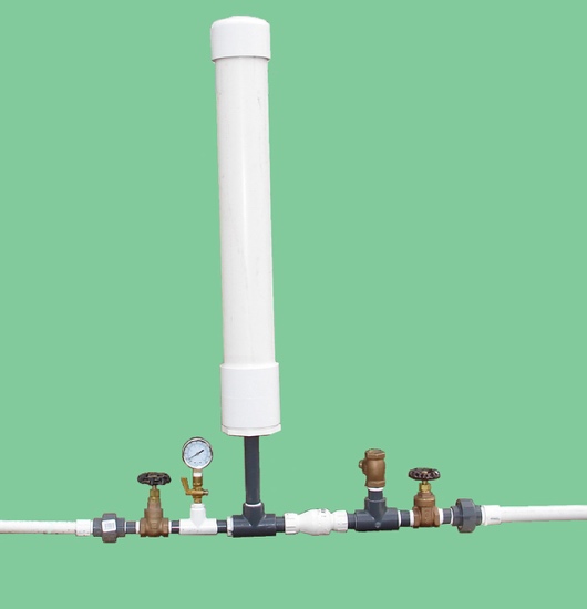
A hydraulic ram pump leverages the energy of falling water to move water to a higher height without the usage of external power. It is made up of a valve, a pressure chamber, and inlet and exit pipes.
A water pump moves water from one area to another, whereas a hydraulic pump"s purpose is to overcome a pressure that is dependent on a load, like a heavy car.

The ideal in hydraulic system designis to match overall efficiencies to the application performance expectation. This requires the designer to first match the motor, then the pump to a specific system performance expectation. Whether the requirement is to do something within a specific time frame, or in handling a given amount of load, the design of the entire system will change depending on the motor selected.
A hydraulic motor is a hydraulic actuator that, when properly connected into a hydraulic system, will produce a rotary actuation. This can be unidirectional or bidirectional depending on the system design. Motors are similar in design to pumps only where a pump takes a rotary actuation to move hydraulic fluid out of the unit, whereas a motor will take flow into itself and put out a rotaryactuation.
The motor selection comes first in the process because application design best practices require that you start with the load requirement, then work back to the prime mover—the pump that will put the fluid power into the motor selected to deliver the performance goal.
Starting torqueis the torque the motor can generate to turn a load when starting from a stop. In general, starting toque is the lowest torque rating of a hydraulic motor due to inefficiencies.
The rotationalspeedof the motor shaft is measured in units of rotations per minute (rpm). Motor speed is a function of hydraulic input flow and motor displacement.
Pressure is generated by resistance to hydraulic flow. The more resistance, the higher the pressure. Common measurement units are pounds per square inch (psi), kilo Pascal’s (kPa) or bar.
Common motor classes and typesGenerally, hydraulic motors are placed into one of two classifications: high speed, low torque (HSLT) or low speed, high torque (LSHT).
Gear motorscome in two varieties—the gerotor/geroller or orbital and external spur gear designs. Orbital styles are classified as LSHT motors; however, some do exist with the HSLT classification. They consist of a matched gear set enclosed in a housing. When hydraulic fluid is moved into the motor, it causes the gears to rotate. One of the gears is connected to the motor output shaft, which produces the motor’s rotary motion. Key features include:
Applications include mobile hydraulics, agricultural machinery to drive conveyor belts, dispersion plates, screw conveyors or fans. Their biggest drawback is that they have a higher noise level.
Vane motorsare typically classified as HSLT units. However, larger displacements will fall into the LSHT range. Hydraulic fluid enters the motor and is applied to a rectangular vane, which slides into and out of the center rotor. This center rotor is connected to the main output shaft. The fluid being applied to the vane causes the output shaft to rotate.
Parker’s vane motors feature a balanced design where the inlet and outlet ports of the motor are applied to sections of the vane cartridge that are 180° apart from each other to ensure that the hydraulic forces are always in balance inside the motor. Key features include:
In-line piston motorsare classified as HSLT. Hydraulic fluid enters the motor and is applied to a series of pistons inside a cylinder barrel. The pistons are pressed against a swash plate, which is at an angle. The pistons push against this angle, which causes the rotation of the swash plate that is mechanically connected to the output shaft of the motor. The swash plate can be a fixed or variable angle. Variable angle motors can have their displacements adjusted between a maximum and minimum setting. The command signals to change the displacement can be electrical, hydraulic or a combination of both.
Bent-axis piston motorsare classified as HSLT. They are similar to inline motors except that the piston barrel is at an angle in relation to the swash plate. Hydraulic fluid enters the motor and is applied to the pistons, which are contained in a cylinder barrel. The pistons are at an angle to the drive shaft, which means that the piston will rotate the shaft as fluid enters the motor.
They can be both fixed and variable displacement. In a variable-displacement bent-axis motor, the cylinder barrel is rotated between maximum and minimum displacements. The command signals to change the displacement can be electrical, hydraulic or a combination of both.
They are best known for high performance, high pressures, high speeds and volumetric mechanical efficiencies in the 97 to 98% range. The also offer quick reaction and precise control. These motors are suitable for applications that require a significant amount of power. They are used to drive mobile and construction equipment, winches, ship-cranes and all kinds of heavy-duty hydraulic equipment for offshore and onshore operations.
Radial piston motorsare LSHT classified. These motors are designed with pistons arranged perpendicular to the output shaft. Typically, the pistons will ride against a cam, which is mechanically connected to the output shaft. The pistons will force the cam to rotate as hydraulic fluid enters the motor.
In general, these motors are fixed displacement. However, some versions will allow for variable displacement. They accomplish this by limiting the number of pistons that can receive hydraulic fluid. Other versions change the internal geometry of the cam the pistons areacting against.
Proper hydraulic motor selection starts with the expected performance required by the application, then works back to the prime mover—the pump. Then it is necessary to evaluate the cost of your motor options along with the degree of complexity you want for the overall system.


 8613371530291