
priming tractor hydraulic pump brands

Ace developed the first hydraulic motor driven pump at the request of John Deere in 1969. Many of the original pumps are still operating today after more than 30 years of service.
Centrifugal pump design provides good resistance to abrasive solutions and extra flow for agitation. The advantages of the hydraulic motor driven pump are mounting versatility, customized performance, and ease of maintenance. All hydraulic driven pumps are equipped with a stainless steel shaft and wear ring for excellent corrosion resistance.MOUNTING VERSATILITY:The location of the pump is not tied to the PTO or engine drive shaft; the pump can be mounted in a variety of locations to suit application requirements.
CUSTOMIZED PERFORMANCE: The performance is dependent on the supply of hydraulic oil to the motor and not necessarily tied to engine speed. A hydraulic driven pump can produce higher pressures than PTO or belt driven pumps. They can also hold constant pressure at varying engine speeds on closed center hydraulic systems.
EASY MAINTENANCE: On a hydraulic driven pump there are no belts to align or break. Separate pump and hydraulic motor shafts simplify repair and replacement. Two main pump bearings support shaft loads. All pumps are equipped with easily replaceable FKM mechanical seals.
The Ace gear type hydraulic motor is more efficient than gerotor type motors, and is less subject to damage by contamination than the gerotor design. A built-in needle valve allows for the bypass of up to 9 GPM excess hydraulic fluid on open center systems. The standard motor has a reverse flow check valve which prevents backward hookup and a coasting check which protects the motor seal from the flywheel effect of the impeller. A restrictor orifice is included with pump models recommended for pressure compensating closed center systems. The Ace Internet Hydraulic Selection Guide is here to help in finding the proper hydraulic pump for your tractor.
The 206 motor requires 7 GPM (26.5 LPM) maximum hydraulic fluid input and fits virtually all tractor hydraulic systems. Recommended for:Pressure Compensating Closed Center Systems
The 206 motor requires 7 GPM (26.5 LPM) maximum hydraulic fluid input and fits virtually all tractor hydraulic systems. Recommended for:Pressure Compensating Closed Center Systems
The 310 motor requires 16 GPM (60.6 LPM) maximum hydraulic fluid input. Recommended for:Large Open Center Systems up to 24 GPM (90.9 LPM) using internal needle valve bypass.
The 206 motor requires 7 GPM (26.5 LPM) maximum hydraulic fluid input and fits virtually all tractor hydraulic systems. Recommended for:Pressure Compensating Closed Center Systems
The 206 motor requires 7 GPM (26.5 LPM) maximum hydraulic fluid input and fits virtually all tractor hydraulic systems. Recommended for:Pressure Compensating Closed Center Systems
The 206 motor requires 7 GPM (26.5 LPM) maximum hydraulic fluid input and fits virtually all tractor hydraulic systems. Recommended for:Pressure Compensating Closed Center Systems
The 206 motor requires 7 GPM (26.5 LPM) maximum hydraulic fluid input and fits virtually all tractor hydraulic systems. Recommended for:Pressure Compensating Closed Center Systems
The Gemini DPK (Dual Pump Kit) was designed to solve these concerns. Pick any two pumps with 204 or 206 motors, and run them from one SCV remote port. Run them at different rates. Shut one pump off while leaving the other pump running. Have your rate controller send PWM signal to one or both of the pumps for precision application.
The 310 motor requires 16 GPM (60.6 LPM) maximum hydraulic fluid input. Recommended for:Large Open Center Systems up to 24 GPM (90.9 LPM) using internal needle valve bypass.
The 206 motor requires 7 GPM (26.5 LPM) maximum hydraulic fluid input and fits virtually all tractor hydraulic systems. Recommended for:Pressure Compensating Closed Center Systems
The 206 motor requires 7 GPM (26.5 LPM) maximum hydraulic fluid input and fits virtually all tractor hydraulic systems.Pressure Compensating Closed Center Systems
The 206 motor requires 7 GPM (26.5 LPM) maximum hydraulic fluid input and fits virtually all tractor hydraulic systems.Pressure Compensating Closed Center Systems
The 206 motor requires 7 GPM (26.5 LPM) maximum hydraulic fluid input and fits virtually all tractor hydraulic systems.Pressure Compensating Closed Center Systems

I reviewed the 5210 technical manual to include the section that speaks to removing and installing the hydraulic pump and there is no mention of a need to re-prime the pump. The pump itself creates the suction, lines coming off the top of the tandem pump are pressure lines. The line coming from the filter is the suction line.
I have replaced the hydraulic fluid and filter and cleaned the pickup screen on my 5210. While I did not startup the tractor no re-priming was needed.
The hydraulic pump assembly contains two pumps, each of different displacements. The 20-cc hydraulic pump supplies oil for the rockshaft and other tractor hydraulics. The 12-cc pump supplies oil for the steering system and transmission lubrication. Both pumps operate identically and use a positive-displacement, external-gear design that moves a set volume of fluid with each revolution. Output volume changes only when the speed of the pump changes. The engine drives the hydraulic pumps from the camshaft drive gear. As the pump gears (C) rotate, they continuously move in and out of mesh with each other. When the gears separate, a vacuum develops which draws oil into the pump inlet (A). The oil continues to move with the gears as they turn. As the gears come back into mesh, they form a seal which prevents oil from returning to the pump inlet. Further meshing forces oil out the pump outlet (D) and into the hydraulic system. This cycle repeats continuously as long as the pump turns.
Rotary Gear Pump, Gear Pump, SS Gear Pump, Crude Oil Pump, Gear Oil pump, Oil Pump, Bitumen Gear Pump, Fuel Injection Gear Pump, LDO pump, Diesel Pump

There are typically three types of hydraulic pump constructions found in mobile hydraulic applications. These include gear, piston, and vane; however, there are also clutch pumps, dump pumps, and pumps for refuse vehicles such as dry valve pumps and Muncie Power Products’ Live PakTM.
The hydraulic pump is the component of the hydraulic system that takes mechanical energy and converts it into fluid energy in the form of oil flow. This mechanical energy is taken from what is called the prime mover (a turning force) such as the power take-off or directly from the truck engine.
With each hydraulic pump, the pump will be of either a uni-rotational or bi-rotational design. As its name implies, a uni-rotational pump is designed to operate in one direction of shaft rotation. On the other hand, a bi-rotational pump has the ability to operate in either direction.
For truck-mounted hydraulic systems, the most common design in use is the gear pump. This design is characterized as having fewer moving parts, being easy to service, more tolerant of contamination than other designs and relatively inexpensive. Gear pumps are fixed displacement, also called positive displacement, pumps. This means the same volume of flow is produced with each rotation of the pump’s shaft. Gear pumps are rated in terms of the pump’s maximum pressure rating, cubic inch displacement and maximum input speed limitation.
Generally, gear pumps are used in open center hydraulic systems. Gear pumps trap oil in the areas between the teeth of the pump’s two gears and the body of the pump, transport it around the circumference of the gear cavity and then force it through the outlet port as the gears mesh. Behind the brass alloy thrust plates, or wear plates, a small amount of pressurized oil pushes the plates tightly against the gear ends to improve pump efficiency.
A cylinder block containing pistons that move in and out is housed within a piston pump. It’s the movement of these pistons that draw oil from the supply port and then force it through the outlet. The angle of the swash plate, which the slipper end of the piston rides against, determines the length of the piston’s stroke. While the swash plate remains stationary, the cylinder block, encompassing the pistons, rotates with the pump’s input shaft. The pump displacement is then determined by the total volume of the pump’s cylinders. Fixed and variable displacement designs are both available.
With a fixed displacement piston pump, the swash plate is nonadjustable. Its proportional output flow to input shaft speed is like that of a gear pump and like a gear pump, the fixed displacement piston pump is used within open center hydraulic systems.
As previously mentioned, piston pumps are also used within applications like snow and ice control where it may be desirable to vary system flow without varying engine speed. This is where the variable displacement piston pump comes into play – when the hydraulic flow requirements will vary based on operating conditions. Unlike the fixed displacement design, the swash plate is not fixed and its angle can be adjusted by a pressure signal from the directional valve via a compensator.
Vane pumps were, at one time, commonly used on utility vehicles such as aerial buckets and ladders. Today, the vane pump is not commonly found on these mobile (truck-mounted) hydraulic systems as gear pumps are more widely accepted and available.
Within a vane pump, as the input shaft rotates it causes oil to be picked up between the vanes of the pump which is then transported to the pump’s outlet side. This is similar to how gear pumps work, but there is one set of vanes – versus a pair of gears – on a rotating cartridge in the pump housing. As the area between the vanes decreases on the outlet side and increases on the inlet side of the pump, oil is drawn in through the supply port and expelled through the outlet as the vane cartridge rotates due to the change in area.
Input shaft rotates, causing oil to be picked up between the vanes of the pump which is then transported to pump outlet side as area between vanes decreases on outlet side and increases on inlet side to draw oil through supply port and expel though outlet as vane cartridge rotates
A clutch pump is a small displacement gear pump equipped with a belt-driven, electromagnetic clutch, much like that found on a car’s air conditioner compressor. It is engaged when the operator turns on a switch inside the truck cab. Clutch pumps are frequently used where a transmission power take-off aperture is not provided or is not easily accessible. Common applications include aerial bucket trucks, wreckers and hay spikes. As a general rule clutch pumps cannot be used where pump output flows are in excess of 15 GPM as the engine drive belt is subject to slipping under higher loads.
What separates this pump from the traditional gear pump is its built-in pressure relief assembly and an integral three-position, three-way directional control valve. The dump pump is unsuited for continuous-duty applications because of its narrow, internal paths and the subsequent likelihood of excessive heat generation.
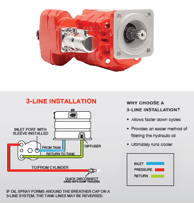
Dump pumps are often direct mounted to the power take-off; however, it is vital that the direct-coupled pumps be rigidly supported with an installer-supplied bracket to the transmission case with the pump’s weight at 70 lbs. With a dump pump, either a two- or three-line installation must be selected (two-line and three-line refer to the number of hoses used to plumb the pump); however, a dump pump can easily be converted from a two- to three-line installation. This is accomplished by inserting an inexpensive sleeve into the pump’s inlet port and uncapping the return port.
Many dump bodies can function adequately with a two-line installation if not left operating too long in neutral. When left operating in neutral for too long however, the most common dump pump failure occurs due to high temperatures. To prevent this failure, a three-line installation can be selected – which also provides additional benefits.
Pumps for refuse equipment include both dry valve and Live Pak pumps. Both conserve fuel while in the OFF mode, but have the ability to provide full flow when work is required. While both have designs based on that of standard gear pumps, the dry valve and Like Pak pumps incorporate additional, special valving.
Primarily used on refuse equipment, dry valve pumps are large displacement, front crankshaft-driven pumps. The dry valve pump encompasses a plunger-type valve in the pump inlet port. This special plunger-type valve restricts flow in the OFF mode and allows full flow in the ON mode. As a result, the horsepower draw is lowered, which saves fuel when the hydraulic system is not in use.
In the closed position, the dry valve allows just enough oil to pass through to maintain lubrication of the pump. This oil is then returned to the reservoir through a bleed valve and small return line. A bleed valve that is fully functioning is critical to the life of this type of pump, as pump failure induced by cavitation will result if the bleed valve becomes clogged by contaminates. Muncie Power Products also offer a butterfly-style dry valve, which eliminates the bleed valve requirement and allows for improved system efficiency.
It’s important to note that with the dry valve, wear plates and shaft seals differ from standard gear pumps. Trying to fit a standard gear pump to a dry valve likely will result in premature pump failure.
Encompasses plunger-type valve in the pump inlet port restricting flow in OFF mode, but allows full flow in ON mode lowering horsepower draw to save fuel when not in use
Wear plates and shaft seals differ from standard gear pumps – trying to fit standard gear pump to dry valve likely will result in premature pump failure
Live Pak pumps are also primarily used on refuse equipment and are engine crankshaft driven; however, the inlet on a Live Pak pump is not outfitted with a shut-off valve. With a Live Pak pump, the outlet incorporates a flow limiting valve. This is called a Live Pak valve. The valve acts as an unloading valve in OFF mode and a flow limiting valve in the ON mode. As a result, the hydraulic system speed is limited to keep within safe operating parameters.
Outlet incorporates flow limiting valve called Live Pak valve – acts as an unloading valve in OFF mode and flow limiting valve in ON mode restricting hydraulic system speed to keep within safe operating parameters

It is helpful in priming pump to fill it with oil prior to installing pump on tractor. Pour oil into intake opening and turn pump in direction of normal rotation until oil comes out pressure opening. If pump does not prime itself readily after starting engine, one or more of the following methods may be used to prime the pump
1) Loosen (plug in front cover of piston pump or) plug at lower front corner on left side of the center housing if equipped with a vane pump and turn enginer over with starter until oil flows

The gear pump is a PD (Positive displacement) pump. It helps to develop a flow by carrying the fluid between repeatedly enclosing interlocking gears or cogs, transferring it automatically using a cyclical pumping action. So, the Gear pump provides a smooth pulseless fluid flow of which rate depends on its gears’ rotational speed.
The gear pump uses the rotating gears or cogs’ action to move fluids. Its rotating part forms a fluid seal by the casing of the pump and creates the suction at the inlet of the gear pump. Fluid pulled into a gear pump is surrounded within the rotating gears or cogs cavities and shifted out to discharge.
External design Gear pump contains two identical and interlocking gears that are supported through separate shafts. The motor is used to drive the first gear which drives the second gear. In a few cases, electrical motors can drive both shafts that are supported with bearings on every side of the casing.When gears move out from the mesh on the pump’s inlet side, they form an extended volume, Fluid flows into the pump’s cavities and entrapped by the edges of gear while gears carry on rotating against the casing of the pump.
The fluid cannot be transferred back over the center, amongst the gears, as they got connected. Close tolerances amongst the casing and the gears let the external gear pump to extend suction over the inlet and prohibit fluid from going back from the pump’s discharge side (Though the low viscosity fluids have more tendency for fluid leakage).
The Internal Design Gear Pump works the same as of External Design Gear Pump except that it’s both interconnected gears have different sizes where one rotates inside of others. It has a larger internal gear which is called the rotor i.e. its edges projecting from the inside. The other external gear of small size mounted into the center of the rotor which is called the idler. It is designed for interconnecting with the outer rotor in a way that edges of gear engage at the one end. The bushing along with a pinion is attached to the casing of the pump which holds inner idle into its location. A crescent shape fixed divider fills the vacant place which is created by the idler’s irregular mounting position. It works like the seal amongst outlet & inlet ports.When gears move out from the mesh on the pump’s inlet side, they form an extended volume, fluid flows into the pump’s cavities, and entrapped by the edges of gear while gears carry on rotating against the partition and casing of the pump.
The gear pump has few moving parts and is very simple and compact. Its pressure power cannot be matched with reciprocating pumps or the rates of flow of the centrifugal pumps. Yet it provides higher throughputs and pressures than lobe pumps or vanes. The gear pump is specifically suitable for fluids of high viscosity and pumping oils.
From the two types of gear pump, the external design has the ability to sustain high flow rates and pressures (more than 3000psi) due to its closer tolerances and stronger shaft support. Internal design provides better suction. It is suitable for fluids of high viscosity but it provides an operating range of 1cp to more than 1,000,000cp. As output depends on the rotational speed, the gear pump is mostly used for blending and metering operations. The gear pump can also be engineered for handling the aggressive liquids. Whereas it is generally made from stainless steel or cast iron, new composites and alloys let the pump handle the corrosive fluids like sodium hypochlorite, sulphuric acid, sodium hydroxide, and ferric chloride.
The external design can be used in lifting machinery, hydraulic power, plant equipment, and vehicles. When the gear pump is driven in reverse, by using the oil which can be pumped from anywhere in the system (generally through a tandem pump within an engine), creates the hydraulic motor. It can be beneficial for providing power in those fields where the electrical system is costly, inconvenient, or bulky. For example, a tractor depends on an external design engine-driven gear pump to power its services.
The gear pump is self-priming yet it can also dry lift, though its priming features can be enhanced by wetting the gears. The gears should not run dry for a prolonged period and must be lubricated through a pumped fluid. Some designs of gear pumps can be operated in both directions (forward or reverse). Since the same gear pump can be utilized for loading and unloading the vessel, for instance.
Close tolerance amongst the casing and gear means that this pump type is vulnerable to wear especially when feeds consisting of entrained solids or the abrasive fluids are used. Though, few pump designs, specifically internal variants that let to handle the solids as well. The external design gear pump has four bearings with tight tolerances. Therefore, it is less suitable to handle abrasive fluids. The internal design gear pump is more robust and has just one bearing (maybe two) to run in a fluid. The gear pump needs to install a strainer on a suction side that can protect it from potential damages of solids.
In general, when a gear pump requires for handling abrasive solids then it’s better to choose a pump with higher capacity that can be run at low speed to avoid wear. But it must keep in mind that the gear pump’s volumetric efficiency becomes lessens at low flow rates and speeds. The gear pump must not be run beyond the recommended speed.
In applications of high temperature, it’s necessary to make sure that an operating range of temperature is compatible along with the specification of the pump. Gears and casings’ thermal expansion lessens clearances in the pump which can lead towards increased wear as well as in extreme circumstances, pump failure.
In spite of the best precautions, the bearings, casing, and gears of the pump succumb to wearing with every passing day. As there is an increase in clearances, a gradual decrease in efficiency happens along with an increase in the flow slip: pumped fluid’ leakage from the expulsion back towards a suction side. The flow slip depends on the clearance’ cube between the casing and cog edge so, practically, wear provide a small impact till a critical stage is reached after which the performance of the pump degrades rapidly.
Gear pumps continue to pump in contrary to reverse pressure then, if downstream blockage happens, it will carry on to the pressurized system till the pipework, pump, or other parts fails. Due to this reason, some gear pumps are used to equip with the relief valves. It’s advisable to use a relief valve anywhere within a system for protecting the downstream equipment.
The internal designs gear pumps that operated at less speed are considered ideal for the shear-sensitive fluids like paint, soaps, and foodstuffs. The lower clearances and higher speeds of eternal design gears make them appropriate for these kinds of applications. The internal design gear pump also prefers where hygiene conditions are more important due to its mechanical simplicity. This is a fact that it has easy to clean, strip down, and reassemble features.
Gear pumps are appropriate for pumping the fluids of high viscosity like foodstuff, oil, paints, or resins. They are used in any kind of application where the output of high pressure or accurate dosing is required. The gear pump output is not affected too much by pressure and they can be used in any type of situation where irregular supply occurs.
The gear pump helps to develop a flow by carrying the fluid between repeatedly enclosing interlocking gears or cogs, transferring it automatically to smooth pulseless flow of which rate depends on its gears’ rotational speed. Two basic design types of gear pumps are external design and internal design.
External design Gear pump contains two identical and interlocking gears that are supported through separate shafts. The Internal Design Gear Pump has two interconnected gears having different sizes where one rotates inside of others.
Gear pumps are appropriate for pumping the fluids of high viscosity like foodstuff, oil, paints, or resins. They are used in any kind of application where the output of high pressure or accurate dosing is required. The external design gear pump is used to sustain high pressure (more than 7500 psi) while the internal design gear pump provides better suction and is more suitable to fluids which are shear sensitive and of high viscosity.

PRIME GUARD Premium Tractor Hydraulic Fluid is a high quality, specially designed lubricant containing anti-rust, anti-foam and oxidation inhibitors; plus, other additives necessary for the wide range of applications recommended by various tractor manufacturers. This product resists thickening in cold weather and thinning in the heat of the summer. It is compounded with detergents to keep transmissions clean and maintain hydraulic control circuits in perfect working condition; and provides excellent protection against seal and pump deterioration.

A gear pump is a type of positive displacement (PD) pump. Gear pumps use the actions of rotating cogs or gears to transfer fluids. The rotating gears develop a liquid seal with the pump casing and create a vacuum at the pump inlet. Fluid, drawn into the pump, is enclosed within the cavities of the rotating gears and transferred to the discharge. A gear pump delivers a smooth pulse-free flow proportional to the rotational speed of its gears.
There are two basic designs of gear pump: internal and external (Figure 1). An internal gear pump has two interlocking gears of different sizes with one rotating inside the other. An external gear pump consists of two identical, interlocking gears supported by separate shafts. Generally, one gear is driven by a motor and this drives the other gear (the idler). In some cases, both shafts may be driven by motors. The shafts are supported by bearings on each side of the casing.
As the gears come out of mesh on the inlet side of the pump, they create an expanded volume. Liquid flows into the cavities and is trapped by the gear teeth as the gears continue to rotate against the pump casing.
No fluid is transferred back through the centre, between the gears, because they are interlocked. Close tolerances between the gears and the casing allow the pump to develop suction at the inlet and prevent fluid from leaking back from the discharge side (although leakage is more likely with low viscosity liquids).
External gear pump designs can utilise spur, helical or herringbone gears (Figure 3). A helical gear design can reduce pump noise and vibration because the teeth engage and disengage gradually throughout the rotation. However, it is important to balance axial forces resulting from the helical gear teeth and this can be achieved by mounting two sets of ‘mirrored’ helical gears together or by using a v-shaped, herringbone pattern. With this design, the axial forces produced by each half of the gear cancel out. Spur gears have the advantage that they can be run at very high speed and are easier to manufacture.
Gear pumps are compact and simple with a limited number of moving parts. They are unable to match the pressure generated by reciprocating pumps or the flow rates of centrifugal pumps but offer higher pressures and throughputs than vane or lobe pumps. External gear pumps are particularly suited for pumping water, polymers, fuels and chemical additives. Small external gear pumps usually operate at up to 3500 rpm and larger models, with helical or herringbone gears, can operate at speeds up to 700 rpm. External gear pumps have close tolerances and shaft support on both sides of the gears. This allows them to run at up to 7250 psi (500 bar), making them well suited for use in hydraulic power applications.
Since output is directly proportional to speed and is a smooth pulse-free flow, external gear pumps are commonly used for metering and blending operations as the metering is continuous and the output is easy to monitor. The low internal volume provides for a reliable measure of liquid passing through a pump and hence accurate flow control. They are also used extensively in engines and gearboxes to circulate lubrication oil. External gear pumps can also be used in hydraulic power applications, typically in vehicles, lifting machinery and mobile plant equipment. Driving a gear pump in reverse, using oil pumped from elsewhere in a system (normally by a tandem pump in the engine), creates a motor. This is particularly useful to provide power in areas where electrical equipment is bulky, costly or inconvenient. Tractors, for example, rely on engine-driven external gear pumps to power their services.
External gear pumps can be engineered to handle aggressive liquids. While they are commonly made from cast iron or stainless steel, new alloys and composites allow the pumps to handle corrosive liquids such as sulphuric acid, sodium hypochlorite, ferric chloride and sodium hydroxide.
External gear pumps are self-priming and can dry-lift although their priming characteristics improve if the gears are wetted. The gears need to be lubricated by the pumped fluid and should not be run dry for prolonged periods. Some gear pump designs can be run in either direction so the same pump can be used to load and unload a vessel, for example.
The close tolerances between the gears and casing mean that these types of pump are susceptible to wear particularly when used with abrasive fluids or feeds containing entrained solids. External gear pumps have four bearings in the pumped medium, and tight tolerances, so are less suited to handling abrasive fluids. For these applications, internal gear pumps are more robust having only one bearing (sometimes two) running in the fluid. A gear pump should always have a strainer installed on the suction side to protect it from large, potentially damaging, solids.
Generally, if the pump is expected to handle abrasive solids it is advisable to select a pump with a higher capacity so it can be operated at lower speeds to reduce wear. However, it should be borne in mind that the volumetric efficiency of a gear pump is reduced at lower speeds and flow rates. A gear pump should not be operated too far from its recommended speed.
For high temperature applications, it is important to ensure that the operating temperature range is compatible with the pump specification. Thermal expansion of the casing and gears reduces clearances within a pump and this can also lead to increased wear, and in extreme cases, pump failure.
Despite the best precautions, gear pumps generally succumb to wear of the gears, casing and bearings over time. As clearances increase, there is a gradual reduction in efficiency and increase in flow slip: leakage of the pumped fluid from the discharge back to the suction side. Flow slip is proportional to the cube of the clearances between the cog teeth and casing so, in practice, wear has a small effect until a critical point is reached, from which performance degrades rapidly.
Gear pumps continue to pump against a back pressure and, if subjected to a downstream blockage will continue to pressurise the system until the pump, pipework or other equipment fails. Although most gear pumps are equipped with relief valves for this reason, it is always advisable to fit relief valves elsewhere in the system to protect downstream equipment.
The high speeds and tight clearances of external gear pumps make them unsuitable for shear-sensitive liquids such as foodstuffs, paint and soaps. Internal gear pumps, operating at lower speed, are generally preferred for these applications.
External gear pumps are commonly used for pumping water, light oils, chemical additives, resins or solvents. They are preferred in any application where accurate dosing is required such as fuels, polymers or chemical additives. The output of a gear pump is not greatly affected by pressure so they also tend to be preferred in any situation where the supply is irregular.
An external gear pump moves a fluid by repeatedly enclosing a fixed volume within interlocking gears, transferring it mechanically to deliver a smooth pulse-free flow proportional to the rotational speed of its gears.
External gear pumps are commonly used for pumping water, light oils, chemical additives, resins or solvents. They are preferred in applications where accurate dosing or high pressure output is required. External gear pumps are capable of sustaining high pressures. The tight tolerances, multiple bearings and high speed operation make them less suited to high viscosity fluids or any abrasive medium or feed with entrained solids.

When you begin working with hydraulic pump drives, they can be a bit overwhelming. But, it doesn"t have to be that way. Below we will dive into some pump drive basic info and review the key manufacturers.
A hydraulic pump drive(also referred to as a pump drive) is a device that connects a prime mover to a hydraulic pump. There are several different sizes & configurations available. There are also several different input options, which we will go into more detail about later.
The multi-pad pump drives have a gear train in them to drive the pumps and can be a 1:1 ratio or an increasing or decreasing ratio to drive the hydraulic pumps at the optimal RPM while running the engine at its optimal RPM.
There are various terms used in the field for pump drives. If you hear any of the below nicknames, they are likely referring to a hydraulic pump drive.
Hydraulic pump drives are found in various applications, with the most common being marine, cranes, drilling rigs, construction equipment, and agricultural applications. They can power hoists, boom cylinders, outriggers, drill heads, and power the machine through hydraulic motors.
As machines have gotten more complex in recent years, they now need power for multiple actions during use. Therefore, it is much easier to design a system that drives these loads hydraulically than drive the loads mechanically.
That is where the hydraulic pump drive comes into play in various applications. Additionally, pump drives are pretty simple, comprised of a gearbox with an input, bearings, gears, and outputs to mount with the hydraulic pumps.
The simplest pump drive available is a single pump direct drive, consisting of a flex plate and bell housing plate coupled to one hydraulic pump. Pump drives come in a variety of output sizes, going up to five outputs.
There are remote inputs, with the most common being keyed input shafts or flanged input shafts. Lastly, there are clutch inputs, with the most common being a mechanically engaged clutch. Palmer Johnson has the resources to also offer pneumatic or hydraulic engaged clutch inputs for pump drives.
The most common pump drive manufacturers are Funk, Durst, and Twin Disc. All three manufacturers offer a full array of pump drive sizes, ranging from one pad all the way up to a five pad option.
In addition, they all offer an expansive list of input and output options as well as several ratio options that vary depending on the particular pump drive model.
Palmer Johnson is an authorized distributor for Funk, Durst, and Twin Disc with decades of experience supporting these product lines. So whether you need a pump drive for a brand new application or need to replace an existing pump drive that is in use, Palmer Johnson has you covered!

Premium quality multi-functional hydraulic oil containing anti-wear and anti-foam additives with rust, oxidation, and corrosion inhibitors. Formulated for agriculture, fleet, and off-road equipment. Provides chatter-free operation of wet brakes, prolongs life of seals and hoses. Protects gears, pumps, and other parts from wear due to high loads. Good all-season performance. Formulated for agriculture, fleet, and off-road equipment.


 8613371530291