
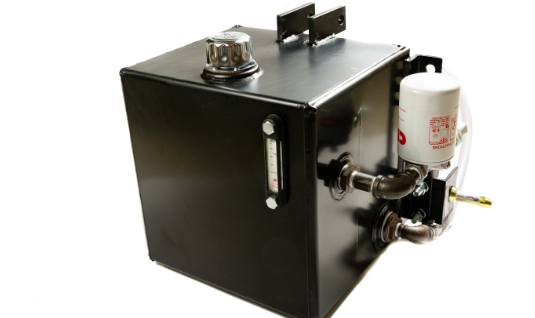
pto driven hydraulic pump with reservoir free sample

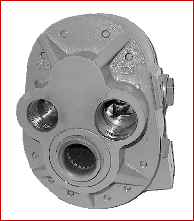
Model GP-PTO is a Power Take Off gear pump constructed with cast iron end plates and aluminium center section. This rear ported pump offers 9.76 in³/rev (160 cm³/rev) displacement and higher flows at reduced engine rpm as compared to other PTO pumps. The standard drive on our rear ported model is a 1 3/8" diameter 21-tooth female spline.

Model GP-PTO is a Power Take Off gear pump constructed with cast iron end plates and aluminium center section. It offers 4 displacement sizes from 3.41-9.76 in³/rev (56-160 cm³/rev). The standard drive is 1 3/8" diameter 6-tooth female spline.
All Star pumps are covered by a limited warranty on materials and workmanship for one year from the date of manufacture. Star will repair or replace at its option any pump in which Star finds manufacturing defects. In order to get warranty service a pump must be returned to the Star plant freight prepaid with a written explanation of the problem.
Light hydraulic oil is recommended for use with Star pumps. Oils with SUS viscosity of 75 to 150 at 100 degrees Fahrenheit will give satisfactory performance (ISO grade 15, 22, or 32). In an emergency situation when the above oils are not available, use 5 W or 10 W motor oil or automatic transmission fluid.
All exposed surfaces of standard Star pumps are painted with one coat of industrial quality paint. Pumps painted with special colors with two coat finishes, or with prime coat only, and pumps with special plated or polished parts, are also available.
Things like restrictions and blockages can impede the flow of fluid to your pump. which could contribute to poor fluid flow. Air leak in suction line. Air present in the pump at startup. Insufficient supply of oil in pump. Clogged or dirty fluid filters. Clogged inlet lines or hoses. Blocked reservoir breather vent. Low oil in the reservoir
Now that we’ve ensured that the directional control is not reversed, it’s time to check that the drive motor itself is turning in the right direction. Sometimes incorrect installation leads to mismatched pipe routings between control valves and motors, which can reverse the direction of flow. Check to see that the motor is turning the pump in the right direction and if not - look at your piping.
Check to ensure that your pump drive motor is turning over and is developing the required speed and torque. In some cases, misalignment can cause binding of the drive shaft, which can prevent the motor from turning. If this is the case, correct the misalignment and inspect the motor for damage. If required, overhaul or replace motor.
Check to ensure the pump to motor coupling is undamaged. A sheared pump coupling is an obvious cause of failure, however the location of some pumps within hydraulic systems makes this difficult to check so it may go overlooked
It is possible that the entire flow could be passing over the relief valve, preventing the pressure from developing. Check that the relief valve is adjusted properly for the pump specifications and the application.
Seized bearings, or pump shafts and other internal damage may prevent the pump from operating all together. If everything else checks out, uncouple the pump and motor and check to see that the pump shaft is able to turn. If not, overhaul or replace the pump.
If your pump is having problems developing sufficient power, following this checklist will help you to pinpoint the problem. In some cases you may find a simple solution is the answer. If your pump is exhibiting any other issues such as noise problems, heat problems or flow problems, you may need to do some more investigation to address the root cause of your pump problem. To help, we’ve created a downloadable troubleshooting guide containing more information about each of these issues. So that you can keep your system up and running and avoid unplanned downtime. Download it here.

Check that the pump shaft is rotating. Even though coupling guards and C-face mounts can make this difficult to confirm, it is important to establish if your pump shaft is rotating. If it isn’t, this could be an indication of a more severe issue, and this should be investigated immediately.
Check the oil level. This one tends to be the more obvious check, as it is often one of the only factors inspected before the pump is changed. The oil level should be three inches above the pump suction. Otherwise, a vortex can form in the reservoir, allowing air into the pump.
What does the pump sound like when it is operating normally? Vane pumps generally are quieter than piston and gear pumps. If the pump has a high-pitched whining sound, it most likely is cavitating. If it has a knocking sound, like marbles rattling around, then aeration is the likely cause.
Cavitation is the formation and collapse of air cavities in the liquid. When the pump cannot get the total volume of oil it needs, cavitation occurs. Hydraulic oil contains approximately nine percent dissolved air. When the pump does not receive adequate oil volume at its suction port, high vacuum pressure occurs.
This dissolved air is pulled out of the oil on the suction side and then collapses or implodes on the pressure side. The implosions produce a very steady, high-pitched sound. As the air bubbles collapse, the inside of the pump is damaged.
While cavitation is a devastating development, with proper preventative maintenance practices and a quality monitoring system, early detection and deterrence remain attainable goals. UE System’s UltraTrak 850S CD pump cavitation sensor is a Smart Analog Sensor designed and optimized to detect cavitation on pumps earlier by measuring the ultrasound produced as cavitation starts to develop early-onset bubbles in the pump. By continuously monitoring the impact caused by cavitation, the system provides a simple, single value to trend and alert when cavitation is occurring.
The oil viscosity is too high. Low oil temperature increases the oil viscosity, making it harder for the oil to reach the pump. Most hydraulic systems should not be started with the oil any colder than 40°F and should not be put under load until the oil is at least 70°F.
Many reservoirs do not have heaters, particularly in the South. Even when heaters are available, they are often disconnected. While the damage may not be immediate, if a pump is continually started up when the oil is too cold, the pump will fail prematurely.
The suction filter or strainer is contaminated. A strainer is typically 74 or 149 microns in size and is used to keep “large” particles out of the pump. The strainer may be located inside or outside the reservoir. Strainers located inside the reservoir are out of sight and out of mind. Many times, maintenance personnel are not even aware that there is a strainer in the reservoir.
The suction strainer should be removed from the line or reservoir and cleaned a minimum of once a year. Years ago, a plant sought out help to troubleshoot a system that had already had five pumps changed within a single week. Upon closer inspection, it was discovered that the breather cap was missing, allowing dirty air to flow directly into the reservoir.
A check of the hydraulic schematic showed a strainer in the suction line inside the tank. When the strainer was removed, a shop rag was found wrapped around the screen mesh. Apparently, someone had used the rag to plug the breather cap opening, and it had then fallen into the tank. Contamination can come from a variety of different sources, so it pays to be vigilant and responsible with our practices and reliability measures.
The electric motor is driving the hydraulic pump at a speed that is higher than the pump’s rating. All pumps have a recommended maximum drive speed. If the speed is too high, a higher volume of oil will be needed at the suction port.
Due to the size of the suction port, adequate oil cannot fill the suction cavity in the pump, resulting in cavitation. Although this rarely happens, some pumps are rated at a maximum drive speed of 1,200 revolutions per minute (RPM), while others have a maximum speed of 3,600 RPM. The drive speed should be checked any time a pump is replaced with a different brand or model.
Every one of these devastating causes of cavitation threatens to cause major, irreversible damage to your equipment. Therefore, it’s not only critical to have proper, proactive practices in place, but also a monitoring system that can continuously protect your valuable assets, such as UE System’s UltraTrak 850S CD pump cavitation senor. These sensors regularly monitor the health of your pumps and alert you immediately if cavitation symptoms are present, allowing you to take corrective action before it’s too late.
Aeration is sometimes known as pseudo cavitation because air is entering the pump suction cavity. However, the causes of aeration are entirely different than that of cavitation. While cavitation pulls air out of the oil, aeration is the result of outside air entering the pump’s suction line.
Several factors can cause aeration, including an air leak in the suction line. This could be in the form of a loose connection, a cracked line, or an improper fitting seal. One method of finding the leak is to squirt oil around the suction line fittings. The fluid will be momentarily drawn into the suction line, and the knocking sound inside the pump will stop for a short period of time once the airflow path is found.
A bad shaft seal can also cause aeration if the system is supplied by one or more fixed displacement pumps. Oil that bypasses inside a fixed displacement pump is ported back to the suction port. If the shaft seal is worn or damaged, air can flow through the seal and into the pump’s suction cavity.
As mentioned previously, if the oil level is too low, oil can enter the suction line and flow into the pump. Therefore, always check the oil level with all cylinders in the retracted position.
If a new pump is installed and pressure will not build, the shaft may be rotating in the wrong direction. Some gear pumps can be rotated in either direction, but most have an arrow on the housing indicating the direction of rotation, as depicted in Figure 2.
Pump rotation should always be viewed from the shaft end. If the pump is rotated in the wrong direction, adequate fluid will not fill the suction port due to the pump’s internal design.
A fixed displacement pump delivers a constant volume of oil for a given shaft speed. A relief valve must be included downstream of the pump to limit the maximum pressure in the system.
After the visual and sound checks are made, the next step is to determine whether you have a volume or pressure problem. If the pressure will not build to the desired level, isolate the pump and relief valve from the system. This can be done by closing a valve, plugging the line downstream, or blocking the relief valve. If the pressure builds when this is done, there is a component downstream of the isolation point that is bypassing. If the pressure does not build up, the pump or relief valve is bad.
If the system is operating at a slower speed, a volume problem exists. Pumps wear over time, which results in less oil being delivered. While a flow meter can be installed in the pump’s outlet line, this is not always practical, as the proper fittings and adapters may not be available. To determine if the pump is badly worn and bypassing, first check the current to the electric motor. If possible, this test should be made when the pump is new to establish a reference. Electric motor horsepower is relative to the hydraulic horsepower required by the system.
For example, if a 50-GPM pump is used and the maximum pressure is 1,500 psi, a 50-hp motor will be required. If the pump is delivering less oil than when it was new, the current to drive the pump will drop. A 230-volt, 50-hp motor has an average full load rating of 130 amps. If the amperage is considerably lower, the pump is most likely bypassing and should be changed.
Figure 4.To isolate a fixed displacement pump and relief valve from the system, close a valve or plug the line downstream (left). If pressure builds, a component downstream of the isolation point is bypassing (right).
The most common type of variable displacement pump is the pressure-compensating design. The compensator setting limits the maximum pressure at the pump’s outlet port. The pump should be isolated as described for the fixed displacement pump.
If pressure does not build up, the relief valve or pump compensator may be bad. Prior to checking either component, perform the necessary lockout procedures and verify that the pressure at the outlet port is zero psi. The relief valve and compensator can then be taken apart and checked for contamination, wear, and broken springs.
Check the tank line temperature of the relief valve with a temperature gun or infrared camera. The tank line should be near ambient temperature. If the line is hot, the relief valve is either stuck partially open or is set too low.
Install a flow meter in the case drain line and check the flow rate. Most variable displacement pumps bypass one to three percent of the maximum pump volume through the case drain line. If the flow rate reaches 10 percent, the pump should be changed. Permanently installing a flow meter in the case drain line is an excellent reliability and troubleshooting tool.
Ensure the compensator is 200 psi above the maximum load pressure. If set too low, the compensator spool will shift and start reducing the pump volume when the system is calling for maximum volume.
Performing these recommended tests should help you make good decisions about the condition of your pumps or the cause of pump failures. If you change a pump, have a reason for changing it. Don’t just do it because you have a spare one in stock.
Conduct a reliability assessment on each of your hydraulic systems so when an issue occurs, you will have current pressure and temperature readings to consult.
Al Smiley is the president of GPM Hydraulic Consulting Inc., located in Monroe, Georgia. Since 1994, GPM has provided hydraulic training, consulting and reliability assessments to companies in t...
For example, Sell points out that the manual for an R-23 Vermeer Twin Rake calls for an 18-gal. reservoir minimum. "Not many tractors have that capacity until you get well over 100 hp," he notes.
"Newer hydraulically-powered rakes, particularly twin rakes, need a hydraulic flow of 20 gal. per minute or more," Sell says. "Some of the older tractors we"ve normally thought of as �rake tractors" just don"t have this kind of hydraulic capacity."
Sell"s neighbor, Don Rodel, Woodville, Wis., wanted to use a Deere 4010 on his Vermeer Twin rake. When he did, though, the hydraulic system got red hot. There wasn"t enough oil in the reservoir and therefore, not enough cooling capacity for the rake. They double-checked the tractor"s hydraulic system to make sure it was operating properly. Then they put Rodel"s 4430 on the rake and its hydraulic system overheated, too.
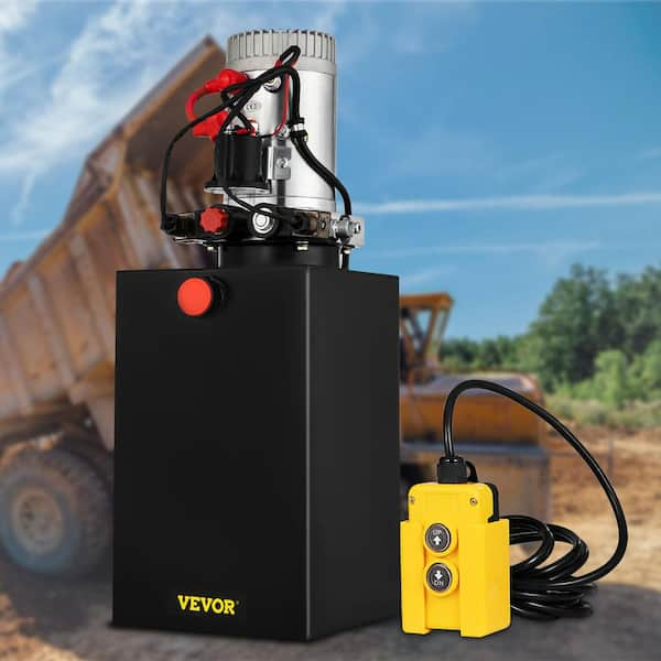
Sell solved the problem by equipping the tractor with a pto-powered hydraulic pump and mounting a 20-gal. reservoir and cooler directly on the rake hitch. The existing rake hydraulics plug into this system, just like they plugged into the tractor"s hydraulic outlets.
"The 4010 has plenty of horsepower to pull the rake and run the PTO. This protects the 4010"s hydraulic system while providing plenty of hydraulic power to the rake," Sells says.
Sell says the conversion was fairly inexpensive, especially when compared with the cost of having to split a tractor open to rebuild a hydraulic pump worn out because of the intense heat build-up.
In addition to farming, Sell operates B-W Machine, a metalworking and machinery repair shop on his farm. "This is the first conversion of this type I"ve made," he says. "If there"s interest, I could put together a kit, along with instructions for mounting it on the rake. There"s enough hydraulic capacity from this pump that we could also plumb it to handle the lift cylinder on the rake so there"d be no hoses to hook up to the tractor at all."
Rodel now uses a David Brown 995 on the rake. He says there was never a time during the first two cuttings this year that the pump or reservoir got warm enough that you couldn"t touch them.
Add-On Hydraulics Allow Small Tractor To Handle Big Twin Rake HAY & FORAGE HARVESTING Rakes (44) 24-5-41 It doesn"t take a lot of horsepower to power a big hay rake but Bob Sell, Woodville, Wisconsin, says it can take quite a bit of hydraulic capacity.For example, Sell points out that the manual for an R-23 Vermeer Twin Rake calls for an 18-gal. reservoir minimum. "Not many tractors have that capacity until you get well over 100 hp," he notes. "Newer hydraulically-powered rakes, particularly twin rakes, need a hydraulic flow of 20 gal. per minute or more," Sell says. "Some of the older tractors we"ve normally thought of as �rake tractors" just don"t have this kind of hydraulic capacity."Sell"s neighbor, Don Rodel, Woodville, Wis., wanted to use a Deere 4010 on his Vermeer Twin rake. When he did, though, the hydraulic system got red hot. There wasn"t enough oil in the reservoir and therefore, not enough cooling capacity for the rake. They double-checked the tractor"s hydraulic system to make sure it was operating properly. Then they put Rodel"s 4430 on the rake and its hydraulic system overheated, too.Sell solved the problem by equipping the tractor with a pto-powered hydraulic pump and mounting a 20-gal. reservoir and cooler directly on the rake hitch. The existing rake hydraulics plug into this system, just like they plugged into the tractor"s hydraulic outlets. "The 4010 has plenty of horsepower to pull the rake and run the PTO. This protects the 4010"s hydraulic system while providing plenty of hydraulic power to the rake," Sells says. Sell says the conversion was fairly inexpensive, especially when compared with the cost of having to split a tractor open to rebuild a hydraulic pump worn out because of the intense heat build-up. In addition to farming, Sell operates B-W Machine, a metalworking and machinery repair shop on his farm. "This is the first conversion of this type I"ve made," he says. "If there"s interest, I could put together a kit, along with instructions for mounting it on the rake. There"s enough hydraulic capacity from this pump that we could also plumb it to handle the lift cylinder on the rake so there"d be no hoses to hook up to the tractor at all."Rodel now uses a David Brown 995 on the rake. He says there was never a time during the first two cuttings this year that the pump or reservoir got warm enough that you couldn"t touch them. Contact: FARM SHOW Followup, Bob Sell, B-W Machine, 2439 County Road BB, Woodville, Wis. 54028 (ph 715 684-2286).
Over the years, revolutionary advancements have been instigated in the tractor control systems’ field. These changes are primarily attributed to integrating various hydraulic inventions in the tipping trailer, braking system, implementing control structure, and steering to enhance this machinery’s optimum functionality. Hydraulic flow and pressure can be translated to motion and forces that enhance a tractor’s capacity to execute tasks that operators cannot perform manually or physically (Gannon, 2017). This paper provides a comprehensive discussion of tractor hydraulics and highlights the benefits of this particular technology.
There are two forms of hydraulic systems: the open- and closed-center structures. The latter is typical in modern-day farm equipment; this includes most tractor models. When in neutral, this system’s closed center valve obstructs oil flow from the pump. This fluid travels to an accumulator, which typically stores it under pressure. The valves also block fluid flow via the center when the hydraulic is in the aforementioned state. A variable flow pump also halts its operation following the closure of the valve. Open hydraulic structures were commonly used in most of the preliminary tractors. When in neutral, this system’s open-center valves link all lines back to the reservoir, directly bypassing the pump, which is always in operation, fostering the constant flow of oil without accumulating pressure. Valves also allow the flow of fluid through the center and into the reservoir during this particular.
Hydraulic oil, particularly non-pressurized fluid, is usually stored in the reservoir. According to Moinfar and Shahgholi (2018), reservoirs are usually vented towards the atmosphere to acclimatize the changing levels of oil. The air vent is fitted with filters to impede the entry of dust or dirt into the reservoir. The reservoir’s metallic walls enhance the cooling process of the fluid by improving the outflow of heat. The decreased pressure within this structure also gives room for dissolved or trapped air to escape from the hydraulic fluid. A sufficient surface area is also essential to foster the dispersal of heat.
JIC and NPTF fittings prevent hydraulic components’ port leakage. NPTF taper pipe threads hinder seepage by using the male-to-female resistance thread taper. On the other hand, JICs sue O-ring (Moinfar & Shahgholi, 2018). The brake hydraulic system’s components are usually joined using hoses and lines. The latter connects the hydraulic system’s stationary parts while hoses consolidate in motion. The hose, tubing, or pipe’s size is crucial (Moinfar & Shahgholi, 2018). If the hose’s size is minimal, the flow of oil increases rapidly, generating heat and causing the fluid to lose power. The cost and time for installing a large hose, on the other hand, can be too high.
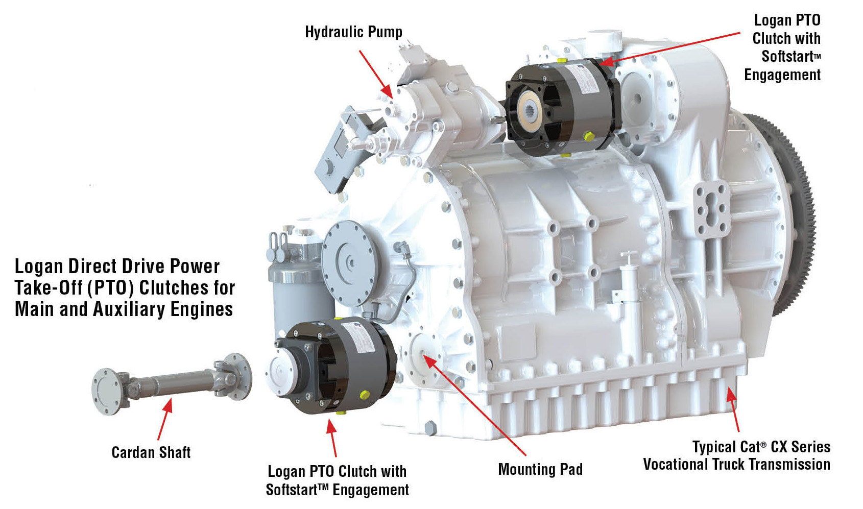
The hydraulic pump plays a crucial role in enhancing fluid transmission from the reservoir and towards the hydraulic system. This process elevates the fluid’s energy level by triggering significant surges in its pressure. A one-phase pump typically has a single flow rate and one maximal pressure. These pumps are usually attached to the PTO shaft or crankshaft on a farm tractor. These pumps are often fitted on manual loaders and backhoes. On the other hand, a two-step pump first generates high fluid volumes by enhancing the cylinder’s rapid in-and-out movements. In case of any form of resistance, an additional gear set is used to create high pressure for splitting and lifting. Nonetheless, the fluid’s volume will reduce significantly during this phase.
Examples of valves fitted in the hydraulic system of a tractor include the flow, pressure, and direction control valve. They function by stopping or impeding liquid or pressure flow and controlling the quantity, pressure, and direction of flow. The motor is located within the pump’s power source, i.e., the cylinder. The fluid with high-pressure levels exerts its action on the piston and rod located within the hydraulic cylinder (Gosaye et al., 2015). Each cylinder stroke converts or translates the power or pressure of the fluid into mechanical force or work. While the piston and rod extend, the reservoir’s oil levels decrease, and when these two devices retract, the fluid flows back to the reservoir.
The instigation of hydraulics triggered significant changes in the agricultural industry, especially concerning the manner and method of production. The adoption of this technology has triggered substantial reductions in the level of manual power or effort needed to perform farm-related activities both in terms of work animals and workers (“How Hydraulics Transformed,” 2019). The tractor has also been effective in decreasing the risks associated with farm-related injuries by minimizing the number of hours individuals spend working in agricultural fields. This invention has also helped restrict the downtime rate amid agricultural operations. Furthermore, it has been crucial in promoting personal and overall productivity and efficiency during practice.
Significant advancements in agricultural engineering, particularly in tractor hydraulics, have triggered farm-related practices’ efficacy and efficiency. The tractor hydraulic system has several components, including the reservoir, pump, and motor. Hydraulics foster a tractor operator’s capacity to execute tasks that demand substantial effort with an electrical switch flip or simple lever push, which, in turn, actuates the hydraulic circuit. Contemporary farming integrates the use of hydraulics for operations that were initially controlled by mechanical means.


 8613371530291