
pto hydraulic pump gearbox free sample

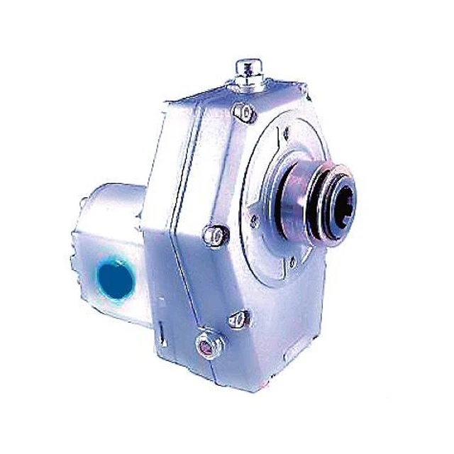
Helical multiplier gearboxes guarantee low-noise and comfortable operation and high transmission performance. Our gearboxes can be used for drills, loaders, forestry trailers, splitters, sweepers or mowers.

Powering a hydraulic pump to a power take-off (PTO) is a common practice. Within mobile hydraulic applications, there are three types of hydraulic pump construction typically found including gear, piston and vane.
Gear pumps are the most common design used in truck mounted hydraulic systems, as the gear pump is relatively inexpensive with its fewer moving parts, ability to be easily serviced and greater tolerance to contamination than other designs.
A hydraulic pump for mobile applications, like the gear, piston or vane pump, can be either direct mounted to the PTO or remote mounted – using a driveline. While each type is a viable option for mounting a hydraulic pump, it is important to understand each type of mount to ensure an effective connection is made between the PTO and pump.
In a direct mount the hydraulic pump is mounted directly to the output flange of the PTO. Direct mounting is the most common type of installation in the mobile equipment industry. When direct mounting a pump it is necessary to:
Select the correct pump rotation to match the PTO output rotation or select what is known as a bi-rotational pump, which tends to have equally sized ports since either can be the inlet or outlet.
For mobile, truck mounted hydraulic systems the most common pump mount is the SAE B, which is a 7/8” diameter shaft with 13 splines – one of the standard pump mounting configurations established by the Society of Automotive Engineers (SAE).
Disadvantages to direct mounting a pump• Concealed maintenance points, which include periodic removal and replacement of grease at the pump to PTO connection
Sometimes it is not possible to direct mount a hydraulic pump, requiring the pump to be remote mounted some distance away from the PTO and then powered from the power take-off by means of a driveline assembly. The correct type and series of driveline must be selected. Solid shafting is not recommended as it cannot be balanced and can vibrate, damaging the PTO and pump shaft seals – causing leaks. The better choice is a balanced, tubular assembly designed to meet the speed, torque and horsepower requirements of the application.
When using a driveline, it is important that it be in phase and incorporates a slip yoke at one end. Round, keyed PTO output shafts are susceptible to failure by high cyclic loading. An out of phase shaft will vibrate and damage the PTO and pump shaft seals while a functioning slip yoke will allow the shaft to adjust for flexing of the truck chassis. As part of a regularly scheduled, preventative maintenance plan, the slip yoke and bearings of the driveline must be lubricated.
Powering a pump to a PTO is a common practice, but selecting whether to direct or remote mount the pump takes understanding and careful consideration. Regardless of the type of mount you select, remember that this understanding of each mount – along with its advantages and its drawbacks – will be the key to creating an effective, lasting connection between the PTO and pump.
Muncie Power Products’ E Series 27 gallon dump pump weighs roughly 70 lbs.—without fluid. That is 70 lbs. of weight hanging on the end of the power take-off (PTO) before fittings are installed, hoses are connected, and oil is added to the reservoir. In comparison, our TG8 Series PTO, which is commonly paired with a dump pump, weighs roughly 23 lbs.
Support brackets for hydraulic pumps are not only for dump pumps. Muncie Power provides a list of criteria in the PTO Operator’s Manual (IN84-03 or IN17-04) to help guide you through the process of determining when and where to use a bracket.
Note:Some transmission makes and models may have different restrictions on pump and PTO bending moment that may necessitate a bracket be used at different weights and/or lengths than those listed above.
If the truck bounces hard enough, the acceleration and pump mass are enough to fracture the PTO housing, resulting in all the transmission fluid dumping out and the pump being dragged behind the truck by the hydraulic hoses.
Attach via two points closest to pump center of gravity in rear of pump, and two points on transmission—extended studs can be used for this connection (Consult the transmission manufacturer for approved mounting points on transmission.),
Figure 1. In the example above, the pump support bracket (shown in yellow) meets Muncie Power"s design requirements for it to be mounted to the transmission and to the hydraulic pump.
The building of the bracket is best done when the PTO and pump are installed on the transmission. A jack should be used to support the pump to remove any stress on the PTO. The two ends of the bracket are bolted to the pump and transmission, respectively, then the middle piece is held in position between the two and tack welded in place.
The bracket can then be removed and given a more permanent weld along with any required gussets and paint. It is critical that the finished bracket not put any stress on the PTO and the pump. The bracket should only support the pump such that the pump itself does not act as a lever arm on the PTO as the truck bounces and jounces during driving or operation of equipment.
Due to the high number of PTO, pump, transmission, and truck combinations possible, Muncie Power does not design, manufacture, or sell pump support brackets. However, we are available to offer suggestions as needed, and can review brackets designs as well.

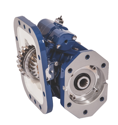
PTO stands for Power Take-Off, which is a common form of mechanical power delivery in the mobile machine market. Here at Flowfit, we are proud to offer industry-leading PTO gearboxes and pump assemblies to transfer high volumes of power and torque from the hydraulic or mechanical systems engine. Typically, these models can be found in high-powered industrial or agricultural machines, including trucks and tractors.
Our PTO gearbox and pump assemblies are available in a wide range of designs and specifications to meet the exact requirements of your system. Typically cast in mechanically-resistant iron or housed in shell-cast aluminium, our models are designed for connecting gear pumps to power take off systems.
For more information on any one of our pump and gearbox assemblies, get in touch with our friendly team of hydraulic and mechanical specialists today on 01584 876 033.

It is recommended to begin analyzing a PTO application using pre-determined necessary technical information about the work output and installation requirements. Go through the following steps to specify a PTO.
Establish the approximate engine speed desired during operation or PTO ratio (if known). PTO speed is stated as a percentage of engine speed. An example being the required pump speed of 1000 RPM and having an engine operating speed of 1500 RPM. The percentage of PTO to engine speed would be calculated to approximately two-thirds, or approximately 67 percent (e.g. 1000/1500 = 66.67, or 67%).
Define the direction of the Driven Equipment Shaft Rotation with there being two choices, engine and opposite-engine. The PTO requirements will be determined by the driven equipment. It is important to note the PTO output shaft rotation listed on the application page is in relation to the vehicle crankshaft rotation as viewed from the rear of the vehicle.(See Figure 1).
Define the duty cycle as intermittent or continuous. Intermittent duty cycles are defined as PTO operations that last for less than five minutes in any fifteen-minute period. Conversely, continuous duty cycles are defined as PTO operations for more than five minutes out of every 15. If an intermittent PTO is used for continuous operation, the required torque must be divided by .70 to get the torque requirement for the driven equipment. The PTO will need to de-rated if it was not designed for continuous duty.
Determine the type and size of the PTO output required (i.e. driveshaft – the size of output required, direct mount pump – mounting flange and shaft type/size).
While not all information is always available, here is an informal guideline that can get you started with the right information to help you select the right PTO for your application.
It is important to remember when the appropriate PTO has been selected through the concluded gathered information, review the application guide, and make sure that all the necessary information has been included. When searching for a PTO in a catalog, please remember to read the footnotes as there may be additional information to consider for specifying a PTO. This can include transmissions not being able to withstand torque capacity of the PTO and the application or some other unique feature of the unit may be mentioned through the footnotes.
To further investigate what different PTOs are being offered, including the new 210 series PTO for the 2020 Ford Super Duty 10R140 Transmission, be sure to check out www.parker.com/chelsea to learn more.

A power take-off or power takeoff (PTO) is one of several methods for taking power from a power source, such as a running engine, and transmitting it to an application such as an attached implement or separate machine.
Semi-permanently mounted power take-offs can also be found on industrial and marine engines. These applications typically use a drive shaft and bolted joint to transmit power to a secondary implement or accessory. In the case of a marine application, such shafts may be used to power fire pumps.
In aircraft applications, such an accessory drive may be used in conjunction with a constant speed drive. Jet aircraft have four types of PTO units: internal gearbox, external gearbox, radial drive shaft, and bleed air, which are used to power engine accessories. In some cases, aircraft power take-off systems also provide for putting power into the engine during engine start.Coffman starter.
Various power transmission methods were available before power take-offs became common, but there were applications which would benefit more from some of the attributes that PTOs would provide. Flat belts were generally only useful for applications where the engine was stationary, such as factory steam engines, portable stationary engines, or traction engines parked in front of the work. For moving vehicles such as a traction engine or early tractor towing a farm implement, the implement could receive rotary power by taking it from one of its own wheels (whose turning was imparted by the towing) and distributing it via roller chains (to a sickle bar"s crank, for example), but such a transmission ceases if the vehicle stops traveling, and the workload"s resistance tends to make the wheel skid rather than turn, even if cleated. The concept of a shaft drive with easily connected and disconnected couplings, and flexibility for driving at changing angles (such as when an articulated tractor-and-trailer combination turns), was a goal to pursue.
Experimental power take-offs were tried as early as 1878, and various homemade versions were constructed over the subsequent decades.International Harvester Company (IHC) was first to market with a PTO on a production tractor, with its model 8-16, introduced in 1918.Case models. In 1920, IHC offered the PTO option on their 15-30 tractor, and it was the first PTO-equipped tractor to be submitted for a Nebraska tractor test. The PTO was a competitive advantage for IHC in the 1920s, and other companies eventually caught up with PTO implementation.
Inside the transmission, the exact point along the gear train where the power is taken off determines whether the PTO can be run independently of vehicle travel (ground speed). Early PTOs were often taken off the main output shaft, meaning that the vehicle had to be "in gear" in order to run the PTO. Later this was improved by so-called live PTO (LPTO) designs, which allow control of the PTO rotation independently of the tractor motion. This is an advantage when the load driven by the PTO requires the tractor motion to slow or stop running to allow the PTO driven equipment to catch up. It also allows operations where the tractor remains parked, such as silo-filling or unloading a manure spreader to a pile or lagoon rather than across a field. In 1945, Cockshutt Farm Equipment Ltd of Brantford, Ontario, Canada, introduced the Cockshutt Model 30 tractor with LPTO. Most PTOs built today
The PTO and its associated shafts and universal joints are a common cause of incidents and injury in farming and industry. According to the National Safety Council, six percent of tractor related fatalities in 1997 in the United States involved the PTO. Incidents can occur when loose clothing is pulled into the shaft, often resulting in bone fractures, loss of limb, or death to its wearer. On April 13, 2009 former Major League Baseball star Mark Fidrych died as a result of a PTO related accident; "He appeared to have been working on the truck when his clothes became tangled in the truck"s power take-off shaft", District Attorney Joseph Early Jr. said in a statement.
Some implements employ light free-spinning protective plastic guards to enshroud the PTO shaft;Health and Safety Executive guidance is contained in a leaflet.
Agricultural PTOs are standardized in dimensions and speed. The ISO standard for PTOs is ISO 500, which as of the 2004 edition was split into three parts:
Due to ever-increasing horsepower requirements from farm implements, and higher horsepower engines being installed in farm tractors, a still larger type (designated as Type 4) has been added to ISO 500. It operates at a higher rotational speed of 1300 rpm in order to allow for power transfer at reduced levels of torque. The shaft has 22 splines with a major diameter of 57.5 millimeters (mm). It is meant to handle PTO powers up to 450 kilowatts (kW), or roughly 600 horsepower (hp).
A 10-spline type was used with some early equipment such as the 1948 Land Rover. A six-spline adapter was usually supplied. It is customary for agricultural machines manufacturers to provide the nominal PTO power specification, an indication of the available instantaneous power at the shaft. Newer tractors may come equipped with 540/540E and/or 1000/1000E options that allow the tractor to power certain low-power-demand implements like hay rakes or tedders using lower engine speeds to maintain the revolutions per minute needed, using less fuel and placing less stress on the engine – thereby improving efficiency and reducing costs.
The first industry standard for PTO design was adopted by ASAE (the American Society of Agricultural Engineers) in April 1927. The PTO rotational speed was specified as 536 ± 10 rpm; the direction was clockwise. The speed was later changed to 540 rpm.
Truck transmissions have one or more locations which allow for a PTO to be mounted. The PTO must be purchased separately and care is required to match the physical interface of the transmission with a compatible PTO. PTO suppliers will usually require details of the make, model and even serial number of the transmission. Care is also needed to ensure that the physical space around the transmission allows for installation of the PTO. The PTO is engaged and disengaged using the main transmission clutch and a remote control mechanism which operates on the PTO itself. Typically, an air valve is used to engage the PTO, but a mechanical linkage, electric or hydraulic mechanism are also options.
Units will be rated according to the continuous and intermittent torque that can be applied through them and different models will offer different "PTO shaft rotation to engine RPM" ratios.
In the majority of cases, the PTO will connect directly to a hydraulic pump. This allows for transmission of mechanical force through the hydraulic fluid system to any location around the vehicle where a hydraulic motor will convert it back into rotary or linear mechanical force. Typical applications include:
A split shaft PTO is mounted to the truck"s drive shaft to provide power to the PTO. Such a unit is an additional gearbox that separates the vehicle"s drive shaft into two parts:
The unit itself is designed to independently divert the engine"s power to either the axle-facing shaft or the additional PTO output shaft. This is done by two independent clutches like tooth or dog clutches, which can be operated at total driveline standstill only. Because the main gearbox changes the rotation speed by selection of a gear, the PTO cannot be operated while the vehicle is moving.
On 4x4 vehicles, only the rear drive shaft is used by the split shaft PTO gearbox, requiring the vehicle"s 4x4 drive scheme to be of the selectable 4WD type to keep the front axle drive shaft completely decoupled during PTO operation.
A "sandwich" type split shaft unit is mounted between engine and transmission and used on road maintenance vehicles, fire fighting vehicles and off-road vehicles. This unit gets the drive directly from the engine shaft and can be capable of delivering up to the complete engine power to the PTO. Usually these units come with their own lubricating system. Due to the sandwich mounting style, the gearbox will be moved away from the engine, requiring the driveline to accommodate the installation.
Privette, Charles (2002-03-01). "Farm Safety & Health - PTO Safety". Department of Agricultural and Biological Engineering. Clemson University. Archived from the original on 2005-03-28. Retrieved 2022-07-29. shields and guards were developed to prevent injury from these rotating shafts
For example our integrated pumpdrive solution has gathered very positive feedback from the fishermen. The plug and play system consists of two pad pump drive with an integrated wet-running clutch on the input shaft. The system is specified for fast running Diesel engines with a slight speed increase for the hydraulic pumps attached. The gearbox is rated for a total power of up to 650kW. The system comes ready assembled and tested with an internal hydraulic system consisting of an integrated oil sump, oil pump, hydraulic valve for regulating the lubrication as well as controlling the wet clutch, oil filter and optional sea water oil cooler.
Combined with Katsa’s micro controller based control system for monitoring and controlling the gearbox functions, Katsa offers a robust, secure and long lifetime solution for all kind of PTO applications. Katsa’s Controller has a local control panel and can be equipped with a remote for the bridge or be integrated in the ships main automation system.
With the modular input configuration, the gearboxes can be mounted whether directly to the fly wheel housing or free standing e.g. on the aft side of a main engine.

Things like restrictions and blockages can impede the flow of fluid to your pump. which could contribute to poor fluid flow. Air leak in suction line. Air present in the pump at startup. Insufficient supply of oil in pump. Clogged or dirty fluid filters. Clogged inlet lines or hoses. Blocked reservoir breather vent. Low oil in the reservoir
Now that we’ve ensured that the directional control is not reversed, it’s time to check that the drive motor itself is turning in the right direction. Sometimes incorrect installation leads to mismatched pipe routings between control valves and motors, which can reverse the direction of flow. Check to see that the motor is turning the pump in the right direction and if not - look at your piping.
Check to ensure that your pump drive motor is turning over and is developing the required speed and torque. In some cases, misalignment can cause binding of the drive shaft, which can prevent the motor from turning. If this is the case, correct the misalignment and inspect the motor for damage. If required, overhaul or replace motor.
Check to ensure the pump to motor coupling is undamaged. A sheared pump coupling is an obvious cause of failure, however the location of some pumps within hydraulic systems makes this difficult to check so it may go overlooked
It is possible that the entire flow could be passing over the relief valve, preventing the pressure from developing. Check that the relief valve is adjusted properly for the pump specifications and the application.
Seized bearings, or pump shafts and other internal damage may prevent the pump from operating all together. If everything else checks out, uncouple the pump and motor and check to see that the pump shaft is able to turn. If not, overhaul or replace the pump.
If your pump is having problems developing sufficient power, following this checklist will help you to pinpoint the problem. In some cases you may find a simple solution is the answer. If your pump is exhibiting any other issues such as noise problems, heat problems or flow problems, you may need to do some more investigation to address the root cause of your pump problem. To help, we’ve created a downloadable troubleshooting guide containing more information about each of these issues. So that you can keep your system up and running and avoid unplanned downtime. Download it here.

“Most importantly, PTOs make fleets money! Typically, the PTO is the first link in the vocational truck’s application chain. The PTO on a truck is the link between the truck’s transmission and the hydraulic pump, blower, or motor doing the work to complete the job. Knowing this, the truck fleet management team needs to install, operate, and maintain it correctly, so the truck is working productively and efficiently,” said Mikel Janitz, Bezares Territory manager & applications engineer.
Bezares is a global manufacturer of PTOs, hydraulic pumps, fittings, tanks, and other mobile power hydraulic components distributed through Eaton in North America.
“The PTO on a truck may only be one component of a much larger picture when it comes to truck fleet management; however, it is paramount to the successful operation of any fleet of hydraulically operated equipment. The PTO converts power from the engine and transmission to an output we can manipulate to drive hydraulic components in various ways to produce a service that generates revenue. This is a simple description of the operation, and we can tie it to fleet management just as easily,” according to Noel Bartlett, field service manager Southwest for Muncie Power Products.
A PTO on a truck, like other components on a truck, require visual inspections and regular maintenance to increase longevity and maintain productivity.
“Productivity drives revenue, therefore, the health and function of the PTO is a valuable and important part of truck fleet management,” Bartlett added. “Having a general understanding of how the PTO is activated, what it does, and how it works helps to reduce downtime, shortens troubleshooting efforts, and provides shop managers and technicians with a higher level of confidence that their fleet is in good working order.”
“A PTO is a gearbox with seals, bearings, and other moving parts. Simple designs and minimal parts equal fewer problems and longer life, resulting in more jobs getting completed on time and budget. Fleet managers focus on cost: the cost of the components, the cost of the entire system, and the total cost of maintenance on a vocational truck. Select a PTO on a truck that is matched correctly to the transmission, application, and operation,” said Janitz of Bezares.
“Gather all the information about the application you are working with before the selection process. A standard PTO on a truck may have a 13 digit or larger part number, and each number or letter is significant. The first determining factor in selecting a PTO is the transmission on the truck,” said Bartlett of Muncie.
“A PTO manufacturer uses the transmission model number to guide you to the correct specification page in their catalog or on their website. There you can find the base model PTO part number needed to work with that transmission. To complete the part number, you need some specific information about the application you are working on. A reliable channel partner or trusted source can help acquire the necessary information to simplify the selection of the proper PTO,” said Bartlett of Muncie.
One factor to consider in selecting a PTO on a truck might come as a surprise, according to Bartlett of Muncie, but is crucial to the process: Find a business partner (PTO supplier) that is as invested in your success as you are.
“Yes, there is a technical side to selecting a PTO but finding a trusted vendor, channel partner, tech support agent, or representative that is willing to guide you through the process can only contribute to the success of the fleet,” he said.
The new Bezares rear-mount PTO incorporates such features as including DIN standard mounting flange and the DIN output all combined with a simple design approach to minimize parts to facilitate ease of installation.
“There are potentially multiple PTOs to choose when building the system. In today’s world, fuel efficiency is a big deal, and managers want to run the truck engine slow to save fuel. This must be balanced with the application torque and horsepower requirements. It also must be balanced with ‘smarter engines’ when emissions are concerned,” said Janitz of Bezares.
“One tip for a continuous application is to select a PTO and ratio that works at a higher engine rpm— approximately 1,100 rpm — and then select the pump to match the required flow rate and pressure. This allows the engine to run effectively as it goes through the regeneration phase,” Janitz added.
“Therefore, utilizing the 8-bolt bottom mount aperture is an ideal solution. The bottom-mount location provides ample room to directly mount the pump to the PTO and facilitates easier hydraulic hose routings,” Janitz said.
“The rear location provides improved ground clearance and more room to directly mount the pump to the PTO and facilitates easier hose routing,” Janitz added.
“The first scenario is a new-build situation where he or she is selecting everything required to drive a hydraulic system or is having a new unit built for the fleet. The second is a repair/replacement scenario where an existing
Be sure to have the transmission model number before you start the process. Bartlett added that it is important to note that a truck’s vehicle identification number (VIN) does not provide the necessary information that a PTO supplier needs to determine the base model for that truck.
“The equipment manufacturer has a list of requirements for the hydraulic system. Make sure to have that information available. This information helps to determine what features are needed to complete the selection such as output shaft size, flange size, activation options, and speed of the PTO,” Bartlett said.
“The challenges here can also be easily overcome with a few quick tips: If the original part number is available on the PTO via a production tag, a PTO can be ordered as a direct replacement. If there is no tag or it is not legible, the manufacturer often engraves the part number under the tag. A flashlight or cell phone camera can help in reading the number,” Bartlett explained. “But, if the PTO part number is not available, the part number of the input gear (the PTO gear that goes into the transmission) will have a part number stamped on it and that can go a long way to identifying the PTO properly.”
“Maintenance can be as simple as looking for leaks and replacing seals, to removing the pump and cleaning and applying grease to the splined pump shaft. Also, if the PTO noise becomes loud or persistent, the PTO should be removed, and inspect the gears for nicks and or metal shavings. If nicks or metal shavings are found, a repair should be completed to ensure continued operation,” said Janitz of Bezares.
Maintenance for a PTO on a truck can also vary based on daily or weekly use, duty cycle times, atmospheric conditions, application, and several other factors.
“For a fleet manager, the maintenance schedule of a truck’s vital fluids, such as engine oil, can be a great time to make a visual inspection of the PTO. Adding the PTO inspection to the regularly scheduled maintenance of the truck reduces downtime and provides the technician the opportunity to talk to the driver about other concerns such as operating noise changes, the functionality of the hydraulic system, changes in duty cycles, etc. This conversation can often help in finding an issue before a downtime failure,” said Bartlett of Muncie.
“The driver knows what the truck and PTO sound like and how they function, and can also identify if something seems to be ‘off.’ Most fleet managers I work with keep a file on each truck and driver’s notes can be maintained here as well,” Bartlett said.
As for specific information about maintenance, each application is different, but there are some common areas to consider when building a maintenance routine for the PTO on a truck.
“First, a solid visual inspection of the entire PTO is a must. This can help identify damage to the housing, surrounding plumbing and wiring, and small leaks, or seepage,” Bartlett said.
“The next, and most likely, inspection would be the mounting of the PTO to the transmission. The bolts holding the PTO to the transmission housing have specific torque requirements to maintain proper backlash and prevent leaks. Inspection of those bolts can be done quickly and prevent future failure as well. If the PTO is ever removed from the transmission visual inspection of the gears and internal components (without disassembly) would give a good snapshot as to the health of the PTO,” Bartlett explained.
“In the past several years, we have seen an increase in the use of automatic transmissions or automatic/manual transmissions. The PTO used in an automatic transmission is often a hot shift, or clutch shift unit, and it operates with an internal clutch pack. These PTOs can be activated in a variety of ways, including while the truck is in operation. This contrasts with the manual transmission PTO that can only be activated when the rotation of the transmission has been stopped,” said Bartlett of Muncie.
“The biggest breakthrough in PTOs has been incorporating better gaskets and seals. Garlock gaskets provide improved leak protection. They perform better than paper gaskets. They are also very dense, which helps reduce creep and facilitates a consistent bolt mounting torque. Viton seal material is one of the best materials used in the industry today. It has ideal physical properties to resist higher heat and aggressive fluid degradation when compared with other common gasket materials,” said Janitz of Bezares.
“The modulated engagement is used to reduce torque spikes on the entire hydraulic system by reducing the start-up speed of the output shaft on the PTO for a moment to allow the system to ramp up to speed slowly. This feature can reduce torque spikes by as much as 70% in some cases and increase the life of the PTO as well as the hydraulic components on the truck,” Bartlett said.
“The Dual Output PTO provides a unique solution, which allows for two PTOs in one eight-bolt location. This saves money, better utilizes space and simplifies installation over a two-PTO (six- and eight-bolt) configuration,” Janitz said.
Lastly, Bartlett noted the growth of plug-and-play wiring harnesses for PTO installation and activation, as well as internal drag brake elements built into the work truck"s PTO.
“Also, technology has given technicians and managers a chance to save time and money because the troubleshooting manuals, installation manuals, and operation manuals specific to the PTO can all be found on manufacturers’ websites and accessible on tablets and cell phones while they are under the truck working,” he said.
“PTO selection can be difficult when it’s not something that you do every day. It is important to have a basic understanding of PTO operation and function, and this can be acquired through trial and error, like so many of the things we do today, or a manager can go online and participate in training through manufactures websites to help them gain additional knowledge,” said Bartlett of Muncie.
“As a fleet manager, you need the truck to be productive, efficient, and reliable. You want it to last a long time, run smooth, and be low maintenance. Selecting the right PTO that gives you the best performance and cost while minimizing and balancing long-term maintenance and repair costs can make a big impact,” said Janitz of Bezares.


 8613371530291