
raymarine type 1 hydraulic pump manual in stock
Boats with traditional hydraulic steering systems will use an Evolution autopilot driven by a hydraulic pump. The pump connects to the boat"s hydraulic steering lines and allow the autopilot to steer the boat by controlling the flow of fluid through the boat"s steering system. The hydraulic pump is controlled by the Evolution autopilot Actuator Control Unit (ACU.)

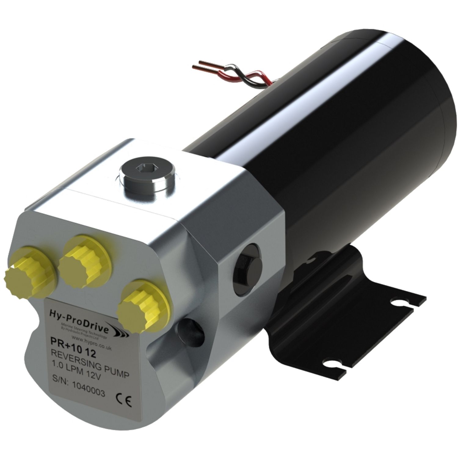
Autopilot Pump Type 2 - Adjustable Reversing Pump - 12V up to 18 CI CylinderNow with ORB Port Connection manifoldReversing pumps are used when hydraulic steering is fitted on boats up to 65 feet L.O...

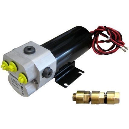
The Type 1 hydraulic reversing pump, 4.9-14cu.in. is a component for Raymarine SmartPilot autopilot system. Designed for boats with existing hydraulic steering systems. To match the drive of your vessel, you need to know the size of the actual hydraulic cylinder RAM or RAMs that are mounted to the rudder on inboard engine boats or the RAM mounted to the drive on outboard engine boats.Best UsePowerboats
This is a replacement motor for the newer style type 1 hydraulic pumps with the fittings coming out horizontal (if the motor was on a table.) WILL NOT WORK WITH OLDER M81120, only the newest style as is depicted in the pictures in the manual. This comes as shown. NOT A COMPLETE AUTOPILOT PUMP – just a replacement motor assembly.

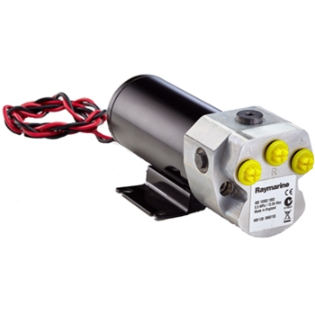
The Type 1 Hydraulic Reversing Pump, is a component for Raymarine SmartPilot autopilot systems. Designed for boats with existing hydraulic steering systems, the Hydraulic Autopilot Pump interfaces with your vessel"s steering system to keep you on the right course.
Notes: In some systems with dual steering rams in parallel, cylinder capacity is the total of both rams. Rams in series only require single capacity valve. Hydraulic steering systems with steering rams over 500cc require our larger constant running pump used in conjunction with the relevant ACU - contact Raymarine for details. An authorized Raymarine dealer is best suited to installing a hydraulic autopilot system. Type 0.5 suitable for Volvo D4/D6 Sterndrive applications.

Distributed by Any reference to Raytheon or RTN in this manual should be interpreted as Raymarine. The names Raytheon and RTN are owned by the Raytheon Company.
Hydraulic Pump Installation Guide Drives covered: M81120 Type 1 Hydraulic Pump 12 V M81119 Type 1 Hydraulic Pump 24 V M81121 Type 2 Hydraulic Pump 12 V M81123 Type 2 Hydraulic Pump 24 V M81122 Type 3 Hydraulic Pump 12 V...
EMC conformance All Raymarine equipment and accessories are designed to the best industry standards for use in the recreational marine environment. The design and manufacture of Raymarine equipment and...
(also known as the Raymarine reversing hydraulic pump). This product is intended to operate the boat’s steering mechanism as part of a Raymarine autopilot system. It is primarily designed for use on boats with an existing hydraulic steering system. Alternatively, you can use this pump on a boat with mechanical steering in conjunction with a secondary steering ram.
Other information Pump dimensions Type 1 (12 V) and Type 2 pumps Figure 2: Type 1 (12 V) and Type 2 pump dimensions Hydraulic Pump - Installation Guide Type 1 (T1) Type 2 (T2) M81120 (12 V) M81121 (12 V)
Hydraulic Pump - Installation Guide Type 3 pump Figure 3: Type 3 pump dimensions Installation instructions Parts required To install this drive you will need: • Parts supplied: • • • Additional parts: • • • Note: Make sure you have obtained these additional parts before you start installation.
Connect to the course computer. Complete the post-installation checks. 1. EMC installation guidelines All Raymarine equipment and accessories are designed to the best industry standards for use in the recreational marine environment. Their design and manufacture conforms to the appropriate...
• Raymarine specified cables are used. Cutting and rejoining these cables can compromise EMC performance and must be avoided unless doing so is detailed in the installation manual.
Connections to other equipment If your Raymarine equipment is to be connected to other equipment using a cable not supplied by Raymarine, a suppression ferrite MUST always be attached to the cable near to the Raymarine unit. 2. Pump mounting Mount the hydraulic pump: •...
Hydraulic Pump - Installation Guide • Try to keep hydraulic fluid loss to a minimum when installing the pump. This will reduce the time and effort required to bleed the system of trapped air after installation: • • WARNING: Before disconnecting any pipes on pressurized systems, you MUST release the pressure at the reservoir by following the manufacturer’s instructions.
Connect the autopilot pump to the steering system as shown in Figure 5. Reservoir pipe Autopilot pump Figure 5: Autopilot pump location for two line systems Hydraulic Pump - Installation Guide Helm pump Check valve (if required) Ram pipes Steering ram...
Hydraulic Pump - Installation Guide Two line pressurized systems Two line pressurized systems have an external pressurized reservoir. This reduces the possibility of introducing air into the system and reduces any steering ‘sponginess’ caused by pipe expansion. Connect the autopilot pump to the steering system as shown in Figure 6.
Connect the autopilot pump to the steering system as shown in Figure 7. Figure 7: Autopilot pump location for three line systems Helm pump Check valve Reservoir pipe Autopilot pump Hydraulic Pump - Installation Guide Ram pipes Steering ram...
Make sure the power supply is switched off before you make any electrical connections. The hydraulic pump has electrical connections for its motor: a red and a black cable. Note: To meet current EMC legislation, you must NOT untwist the pump cables, and you must NOT remove the suppression ferrite.
M81167) across these pipes (as shown in Figure 9). Connect the bypass valve to the CLUTCH terminals on the course • computer using at least 1.5 mm Hydraulic Pump - Installation Guide Cable gauge (AWG) up to 3 m (10 ft)
Hydraulic Pump - Installation Guide Note: Follow the manufacturer’s instructions for mounting the hydraulic ram and reservoir. Figure 9: Connecting to a secondary steering ram 5. Post-installation check WARNING: Keep clear of moving steering systems at all times. Protect moving parts from access during normal use.
Bleeding the system Bleeding the hydraulic system correctly is one of the most important steps when installing the autopilot hydraulic pump. If there is any air in the system the steering will feel spongy, particularly when you turn the wheel to hardover.
Authorized Service Representatives. If you encounter any difficulties with this product, please contact either your national distributor, or your service representative, or the Raymarine Technical Services Call Center. Refer to the back cover or the Worldwide Distributor List for contact details.
Fax +44 (0)23 9269 4642 www.raymarine.com Raymarine Technical Services Call Center UK: +44 (0)23 9271 4713 or +44 (0)23 9269 3611 ext. 1083 Hydraulic Pump - Installation Guide Raymarine Inc 22 Cotton Road, Suite 280 Nashua NH 03063-4219, USA Telephone +1 603 881 5200 Fax +1 603 864 4756 www.raymarine.com...
Hydraulic Pump Installation Guide Drives covered: E12139 Type 0.5 Hydraulic Pump 12 V M81120 Type 1 Hydraulic Pump 12 V M81119 Type 1 Hydraulic Pump 24 V M81121 Type 2 Hydraulic Pump 12 V M81123 Type 2 Hydraulic Pump 24 V...
EMC performance throughout the installation. Suppression ferrites Figure 1 shows typical cable suppression ferrites used with Raymarine equipment. Always use the ferrites supplied by Raymarine.
D3548-2 Figure 1 Connections to other equipment If your Raymarine equipment is to be connected to other equipment using a cable not supplied by Raymarine, a suppression ferrite MUST always be attached to the cable near to the Raymarine unit.
To the best of our knowledge, the information in this handbook was correct when it went to press. However, Raymarine cannot accept liability for any inaccuracies or omissions it may contain. In addition, our policy of continuous product improvement may change specifications without notice.
Installation steps WARNING Electrical safety Make sure you have switched off the power supply before you start installing this product. Follow these steps to install your hydraulic pump: page 3 Consult the EMC installation guidelines. page 10 Mount the pump. page 11 Connect to the hydraulic steering system.
2. Pump mounting Location requirements • pump is designed for below-deck installations only. • fit pump to a substantial structure to avoid vibration that could damage the pipes. • mount away from sources of heat and excessive vibration and fumes. •...
General guidelines • All ports on the autopilot pump are in BSPP parallel threaded. If you need to convert to in NPT, use the three BSPP to NPT adaptors (supplied). Use only bonded rubber / metal washers to seal the fittings. Do NOT use tapered adapters, sealing compound, or PTFE tape.
Helm pump Ram pipes Reservoir pipe Steering ram Autopilot pump Figure 6 Two line pressurized systems Two line pressurized systems have an external pressurized reservoir. This reduces the possibility of introducing air into the system and reduces any steering ‘sponginess’ caused by pipe expansion.
Helm pump Reservoir pipe Pressurized reservoir Ram pipes Autopilot Steering ram pump Figure 7 Three line systems In a three line system, the hydraulic fluid flows in only one direction: • out of the helm pump to the ram • returning from the other side of the ram to the reservoir via a common return line The system will include a check valve block to direct all returned fluid from the ram back to the reservoir.
Helm pump Check valve Reservoir pipe Ram pipes Autopilot pump Steering ram Figure 8 4. Connecting to the course computer or ACU WARNING Electrical safety Make sure you have switched off the power supply before you start installing this product. The hydraulic pump has electrical connections for its motor: a red and a black cable.
1. Measure the distance of cable run from the pump to the course computer or ACU, then use Table 1-3 to identify the appropriate cable sizes. 2. Join these cables to the ones on the pump using appropriate electrical connectors or junction boxes at the correct power rating.
Table 1-3: Recommended cable sizes (Continued) Copper area Cable length Cable gauge (pump to course computer or ACU) (AWG) Type 2 drive 24 V up to 3 m (10 ft) up to 5 m (16 ft) up to 10 m (32 ft) up to 16 m (52 ft) Type 3 drive 12 V up to 5 m (16 ft)
5. Post-installation check WARNING Steering systems Keep clear of moving steering systems at all times. Protect moving parts from access during normal use. Check the following points after installing the pump: 1. Is the pump installed in such a way that hose lengths are kept to a minimum? 2.
1. With the system in auto mode, press the -10 button ten times: • the autopilot pump will try to drive the rudder to port. • counter this rudder movement by turning the helm to starboard to keep the rudder stationary.
Maintenance On a regular basis: • check that all connections and mountings are secure. • check pipes and cables for any signs of wear or damage. • check pipes and joints for any leaks. Pump maintenance The pump contains no user-serviceable parts. Contact your dealer for more information. Motor maintenance The motor contains no user-serviceable parts.
Product support Raymarine products are supported by a worldwide network of distributors and Authorized Service Representatives. If you encounter any difficulties with this product, please contact either your national distributor, or your service representative, or the Raymarine Technical Support Call Center.

The reversing hydraulic pump is designed to be used in conjunction with a steering system equipped with 4.9-14 cubic inch (80cc - 230cc) hydraulic steering rams.
The reversing hydraulic pump is a high quality, reliable product designed for use with steering systems equipped with 4.9-14 cubic inch (80cc - 230cc) hydraulic steering rams.
This pump will allow the operator to move the steering ram in either direction by simply reversing the flow of hydraulic fluid from one side of the pump to the other.

This Hydraulic Pump is built to operate the steering mechanism of the boat playing an important part in a Raymarine autopilot system. Designed for use on boats with an existing hydraulic steering system or for use in a boat with mechanical steering in conjunction with a secondary steering ram. Built with a precision gear pump and a check valve driven by a servo motor. Type 1 (12v)

Raymarine Evolution pilots connect to hydraulic steering systems using a rugged hydraulic pump matched to the capacity of the hydraulic steering system. To calculate the drive unit needed, you will need the size (in cc) of the hydraulic cylinder(s) mounted to the rudder or inboard engine, or the drive unit on your outboard. Info on which drive is right for you is available in the downloads section below. Alternatively if you know the brand and model of the hydraulic cylinder, click the cross reference chart in the downloads section


 8613371530291