
running hydraulic pump dry free sample
Dry lift pumping applications often require lifting a fluid from below the level of the pump. This is generally not a problem for a positive displacement pump that is primed with fluid. However, getting the pump to self-prime depends not only on the characteristics of the pump, but also on the design of the system and the operating conditions. To understand better the application of a pump required to self-prime, let"s discuss some pump fundamentals and good design practices.
Self-priming with a liquid level below the pump requires lifting the fluid. This means that the pump has to develop enough negative pressure (or vacuum) to pull the fluid up the inlet line into the pump. It is important to note that Micropump® products operate very well under high vacuum fluid conditions. However, when a pump is attempting to prime without fluid inside the pump, it is essentially pumping air. Although Micropump gear pumps are intended for use as fluid pumps, they are able to move air because the internal clearances are relatively small.
The amount of air that a pump is able to move depends on the system design, the type of pump, the amount of internal clearance, how well the internal clearances are sealed, the speed of operation, and the characteristics of the fluid to be pumped.
The first thing to consider in a self-priming application is whether or not it is absolutely necessary to make the pump perform this function. It is always good design practice to avoid making the pump dry lift. A flooded inlet is best. However, if it is necessary for the pump to dry lift, it is recommended that the lift elevation be kept to a minimum.
In some cases a flooded inlet is not enough. Pumping out of a condenser or evacuated reservoir may require additional energy to get the fluid into the pump. It may be necessary to raise the reservoir up 10 meters (30 feet), or more, to provide the necessary inlet pressure needed to fill the pump.
The outlet condition of the pump will also affect the ability of the pump to self-prime. If the pump outlet is blocked or restricted, the air being evacuated from the inlet side has nowhere to go except to leak back through the internal clearances of the pump, and the vacuum created will be considerably reduced.
The type of pump is the next consideration in a self-prime application. Micropump manufactures two types of positive displacement gear pumps: a conventional cavity style and a suction shoe design. In general, the conventional cavity style, such as the Series GJ, is preferred. This series has a fixed cavity with small internal clearances, which make its sealing capabilities very good.
There are three gear materials available in the cavity design: PTFE, Ryton and PEEK. PTFE gears have a relatively high coefficient of thermal expansion compared with stainless steel. This means that if the pump is run dry for an extended period, the gears will heat up and try to expand beyond their internal clearances. This will generally decouple the pump and wear the tips of the gears in the process. This will reduce the volumetric efficiency of the pump, as well as its ability to self-prime.
If PTFE gears are not required, consider Ryton or PEEK gears. These materials have better wear characteristics than PTFE and can be run dry for a longer period of time without damage. Micropump recommends that our pumps never be run dry; however, we have heard claims of pumps with Ryton gears accidentally being run dry for extended periods, and then restarted with fluid, showing no significant loss in performance.
The second type of positive displacement gear pump manufactured by Micropump is the “Suction Shoe” design. In this design, the gears are sealed by a floating “shoe” that is pressure loaded by the differential pressure developed by the pump. In addition, there are two types of suction shoe pumps available: one with graphite components and the other with Ryton or PEEK.
The Series GA pumps use carbon graphite gears (X21, V21, and V23) and suction shoes that are machined to very close tolerances. This low displacement, high precision pump has very small internal clearances and uses a bias spring to physically hold the suction shoe against the gears when self-priming. In this case, these features prevail over the inherent self-priming problems in this design. The design gives the Series GA pumps have very good self-priming characteristics.
In most cases, moisture will improve the sealing of the internal clearances. All Micropump pumps are tested before shipment so they will generally have some fluid left inside. However, if it is possible to wet the gears before starting, the self-priming capability of the pump will significantly improve.
Speed of operation is also important in self-priming. In general, a small displacement pump running at a higher speed will lift better than a larger displacement pump at a lower speed. However, this relationship is not proportional.
There are several types of fluid that are difficult to lift regardless of the pump and system. These include volatile, or low-viscosity fluids, or fluids at high temperature, which can reach their vapor pressure in the inlet line before reaching the pump. Fluids with specific gravities higher than water require higher vacuum to lift the same distance. Also, fluids with high viscosities need more vacuum to overcome viscous drag in the inlet line.
It must be noted that when pumping volatile fluids, such as from a barrel, the fluid path should always be grounded. It is possible for static discharge to occur and cause a spark or fire.
In conclusion, applications requiring a pump to self-prime can be successful if the proper pump design and drive are selected, the properties of the fluid are considered, and good design practices are followed. The pump selection should consider materials and self-priming capability, as well as operating performance. The system should be designed so that lift elevation is minimized and the outlet of the pump is not restricted.
A gear pump is a type of positive displacement (PD) pump. It moves a fluid by repeatedly enclosing a fixed volume using interlocking cogs or gears, transferring it mechanically using a cyclic pumping action. It delivers a smooth pulse-free flow proportional to the rotational speed of its gears.
Gear pumps use the actions of rotating cogs or gears to transfer fluids. The rotating element develops a liquid seal with the pump casing and creates suction at the pump inlet. Fluid, drawn into the pump, is enclosed within the cavities of its rotating gears and transferred to the discharge. There are two basic designs of gear pump: external and internal(Figure 1).
An external gear pump consists of two identical, interlocking gears supported by separate shafts. Generally, one gear is driven by a motor and this drives the other gear (the idler). In some cases, both shafts may be driven by motors. The shafts are supported by bearings on each side of the casing.
As the gears come out of mesh on the inlet side of the pump, they create an expanded volume. Liquid flows into the cavities and is trapped by the gear teeth as the gears continue to rotate against the pump casing.
No fluid is transferred back through the centre, between the gears, because they are interlocked. Close tolerances between the gears and the casing allow the pump to develop suction at the inlet and prevent fluid from leaking back from the discharge side (although leakage is more likely with low viscosity liquids).
An internal gear pump operates on the same principle but the two interlocking gears are of different sizes with one rotating inside the other. The larger gear (the rotor) is an internal gear i.e. it has the teeth projecting on the inside. Within this is a smaller external gear (the idler –only the rotor is driven) mounted off-centre. This is designed to interlock with the rotor such that the gear teeth engage at one point. A pinion and bushing attached to the pump casing holds the idler in position. A fixed crescent-shaped partition or spacer fills the void created by the off-centre mounting position of the idler and acts as a seal between the inlet and outlet ports.
As the gears come out of mesh on the inlet side of the pump, they create an expanded volume. Liquid flows into the cavities and is trapped by the gear teeth as the gears continue to rotate against the pump casing and partition.
Gear pumps are compact and simple with a limited number of moving parts. They are unable to match the pressure generated by reciprocating pumps or the flow rates of centrifugal pumps but offer higher pressures and throughputs than vane or lobe pumps. Gear pumps are particularly suited for pumping oils and other high viscosity fluids.
Of the two designs, external gear pumps are capable of sustaining higher pressures (up to 3000 psi) and flow rates because of the more rigid shaft support and closer tolerances. Internal gear pumps have better suction capabilities and are suited to high viscosity fluids, although they have a useful operating range from 1cP to over 1,000,000cP. Since output is directly proportional to rotational speed, gear pumps are commonly used for metering and blending operations. Gear pumps can be engineered to handle aggressive liquids. While they are commonly made from cast iron or stainless steel, new alloys and composites allow the pumps to handle corrosive liquids such as sulphuric acid, sodium hypochlorite, ferric chloride and sodium hydroxide.
External gear pumps can also be used in hydraulic power applications, typically in vehicles, lifting machinery and mobile plant equipment. Driving a gear pump in reverse, using oil pumped from elsewhere in a system (normally by a tandem pump in the engine), creates a hydraulic motor. This is particularly useful to provide power in areas where electrical equipment is bulky, costly or inconvenient. Tractors, for example, rely on engine-driven external gear pumps to power their services.
Gear pumps are self-priming and can dry-lift although their priming characteristics improve if the gears are wetted. The gears need to be lubricated by the pumped fluid and should not be run dry for prolonged periods. Some gear pump designs can be run in either direction so the same pump can be used to load and unload a vessel, for example.
The close tolerances between the gears and casing mean that these types of pump are susceptible to wear particularly when used with abrasive fluids or feeds containing entrained solids. However, some designs of gear pumps, particularly internal variants, allow the handling of solids. External gear pumps have four bearings in the pumped medium, and tight tolerances, so are less suited to handling abrasive fluids. Internal gear pumps are more robust having only one bearing (sometimes two) running in the fluid. A gear pump should always have a strainer installed on the suction side to protect it from large, potentially damaging, solids.
Generally, if the pump is expected to handle abrasive solids it is advisable to select a pump with a higher capacity so it can be operated at lower speeds to reduce wear. However, it should be borne in mind that the volumetric efficiency of a gear pump is reduced at lower speeds and flow rates. A gear pump should not be operated too far from its recommended speed.
For high temperature applications, it is important to ensure that the operating temperature range is compatible with the pump specification. Thermal expansion of the casing and gears reduces clearances within a pump and this can also lead to increased wear, and in extreme cases, pump failure.
Despite the best precautions, gear pumps generally succumb to wear of the gears, casing and bearings over time. As clearances increase, there is a gradual reduction in efficiency and increase in flow slip: leakage of the pumped fluid from the discharge back to the suction side. Flow slip is proportional to the cube of the clearance between the cog teeth and casing so, in practice, wear has a small effect until a critical point is reached, from which performance degrades rapidly.
Gear pumps continue to pump against a back pressure and, if subjected to a downstream blockage will continue to pressurise the system until the pump, pipework or other equipment fails. Although most gear pumps are equipped with relief valves for this reason, it is always advisable to fit relief valves elsewhere in the system to protect downstream equipment.
Internal gear pumps, operating at low speed, are generally preferred for shear-sensitive liquids such as foodstuffs, paint and soaps. The higher speeds and lower clearances of external gear designs make them unsuitable for these applications. Internal gear pumps are also preferred when hygiene is important because of their mechanical simplicity and the fact that they are easy to strip down, clean and reassemble.
Gear pumps are commonly used for pumping high viscosity fluids such as oil, paints, resins or foodstuffs. They are preferred in any application where accurate dosing or high pressure output is required. The output of a gear pump is not greatly affected by pressure so they also tend to be preferred in any situation where the supply is irregular.
A gear pump moves a fluid by repeatedly enclosing a fixed volume within interlocking cogs or gears, transferring it mechanically to deliver a smooth pulse-free flow proportional to the rotational speed of its gears. There are two basic types: external and internal. An external gear pump consists of two identical, interlocking gears supported by separate shafts. An internal gear pump has two interlocking gears of different sizes with one rotating inside the other.
Gear pumps are commonly used for pumping high viscosity fluids such as oil, paints, resins or foodstuffs. They are also preferred in applications where accurate dosing or high pressure output is required. External gear pumps are capable of sustaining higher pressures (up to 7500 psi) whereas internal gear pumps have better suction capabilities and are more suited to high viscosity and shear-sensitive fluids.

Check that the electric motor is running. Although this is a simple concept, before you begin replacing parts, it’s critical that you make sure the electric motor is running. This can often be one of the easiest aspects to overlook, but it is necessary to confirm before moving forward.
Check that the pump shaft is rotating. Even though coupling guards and C-face mounts can make this difficult to confirm, it is important to establish if your pump shaft is rotating. If it isn’t, this could be an indication of a more severe issue, and this should be investigated immediately.
Check the oil level. This one tends to be the more obvious check, as it is often one of the only factors inspected before the pump is changed. The oil level should be three inches above the pump suction. Otherwise, a vortex can form in the reservoir, allowing air into the pump.
What does the pump sound like when it is operating normally? Vane pumps generally are quieter than piston and gear pumps. If the pump has a high-pitched whining sound, it most likely is cavitating. If it has a knocking sound, like marbles rattling around, then aeration is the likely cause.
Cavitation is the formation and collapse of air cavities in the liquid. When the pump cannot get the total volume of oil it needs, cavitation occurs. Hydraulic oil contains approximately nine percent dissolved air. When the pump does not receive adequate oil volume at its suction port, high vacuum pressure occurs.
This dissolved air is pulled out of the oil on the suction side and then collapses or implodes on the pressure side. The implosions produce a very steady, high-pitched sound. As the air bubbles collapse, the inside of the pump is damaged.
While cavitation is a devastating development, with proper preventative maintenance practices and a quality monitoring system, early detection and deterrence remain attainable goals. UE System’s UltraTrak 850S CD pump cavitation sensor is a Smart Analog Sensor designed and optimized to detect cavitation on pumps earlier by measuring the ultrasound produced as cavitation starts to develop early-onset bubbles in the pump. By continuously monitoring the impact caused by cavitation, the system provides a simple, single value to trend and alert when cavitation is occurring.
The oil viscosity is too high. Low oil temperature increases the oil viscosity, making it harder for the oil to reach the pump. Most hydraulic systems should not be started with the oil any colder than 40°F and should not be put under load until the oil is at least 70°F.
Many reservoirs do not have heaters, particularly in the South. Even when heaters are available, they are often disconnected. While the damage may not be immediate, if a pump is continually started up when the oil is too cold, the pump will fail prematurely.
The suction filter or strainer is contaminated. A strainer is typically 74 or 149 microns in size and is used to keep “large” particles out of the pump. The strainer may be located inside or outside the reservoir. Strainers located inside the reservoir are out of sight and out of mind. Many times, maintenance personnel are not even aware that there is a strainer in the reservoir.
The suction strainer should be removed from the line or reservoir and cleaned a minimum of once a year. Years ago, a plant sought out help to troubleshoot a system that had already had five pumps changed within a single week. Upon closer inspection, it was discovered that the breather cap was missing, allowing dirty air to flow directly into the reservoir.
A check of the hydraulic schematic showed a strainer in the suction line inside the tank. When the strainer was removed, a shop rag was found wrapped around the screen mesh. Apparently, someone had used the rag to plug the breather cap opening, and it had then fallen into the tank. Contamination can come from a variety of different sources, so it pays to be vigilant and responsible with our practices and reliability measures.
The electric motor is driving the hydraulic pump at a speed that is higher than the pump’s rating. All pumps have a recommended maximum drive speed. If the speed is too high, a higher volume of oil will be needed at the suction port.
Due to the size of the suction port, adequate oil cannot fill the suction cavity in the pump, resulting in cavitation. Although this rarely happens, some pumps are rated at a maximum drive speed of 1,200 revolutions per minute (RPM), while others have a maximum speed of 3,600 RPM. The drive speed should be checked any time a pump is replaced with a different brand or model.
Every one of these devastating causes of cavitation threatens to cause major, irreversible damage to your equipment. Therefore, it’s not only critical to have proper, proactive practices in place, but also a monitoring system that can continuously protect your valuable assets, such as UE System’s UltraTrak 850S CD pump cavitation senor. These sensors regularly monitor the health of your pumps and alert you immediately if cavitation symptoms are present, allowing you to take corrective action before it’s too late.
Aeration is sometimes known as pseudo cavitation because air is entering the pump suction cavity. However, the causes of aeration are entirely different than that of cavitation. While cavitation pulls air out of the oil, aeration is the result of outside air entering the pump’s suction line.
Several factors can cause aeration, including an air leak in the suction line. This could be in the form of a loose connection, a cracked line, or an improper fitting seal. One method of finding the leak is to squirt oil around the suction line fittings. The fluid will be momentarily drawn into the suction line, and the knocking sound inside the pump will stop for a short period of time once the airflow path is found.
A bad shaft seal can also cause aeration if the system is supplied by one or more fixed displacement pumps. Oil that bypasses inside a fixed displacement pump is ported back to the suction port. If the shaft seal is worn or damaged, air can flow through the seal and into the pump’s suction cavity.
As mentioned previously, if the oil level is too low, oil can enter the suction line and flow into the pump. Therefore, always check the oil level with all cylinders in the retracted position.
If a new pump is installed and pressure will not build, the shaft may be rotating in the wrong direction. Some gear pumps can be rotated in either direction, but most have an arrow on the housing indicating the direction of rotation, as depicted in Figure 2.
Pump rotation should always be viewed from the shaft end. If the pump is rotated in the wrong direction, adequate fluid will not fill the suction port due to the pump’s internal design.
A fixed displacement pump delivers a constant volume of oil for a given shaft speed. A relief valve must be included downstream of the pump to limit the maximum pressure in the system.
After the visual and sound checks are made, the next step is to determine whether you have a volume or pressure problem. If the pressure will not build to the desired level, isolate the pump and relief valve from the system. This can be done by closing a valve, plugging the line downstream, or blocking the relief valve. If the pressure builds when this is done, there is a component downstream of the isolation point that is bypassing. If the pressure does not build up, the pump or relief valve is bad.
If the system is operating at a slower speed, a volume problem exists. Pumps wear over time, which results in less oil being delivered. While a flow meter can be installed in the pump’s outlet line, this is not always practical, as the proper fittings and adapters may not be available. To determine if the pump is badly worn and bypassing, first check the current to the electric motor. If possible, this test should be made when the pump is new to establish a reference. Electric motor horsepower is relative to the hydraulic horsepower required by the system.
For example, if a 50-GPM pump is used and the maximum pressure is 1,500 psi, a 50-hp motor will be required. If the pump is delivering less oil than when it was new, the current to drive the pump will drop. A 230-volt, 50-hp motor has an average full load rating of 130 amps. If the amperage is considerably lower, the pump is most likely bypassing and should be changed.
Figure 4.To isolate a fixed displacement pump and relief valve from the system, close a valve or plug the line downstream (left). If pressure builds, a component downstream of the isolation point is bypassing (right).
The most common type of variable displacement pump is the pressure-compensating design. The compensator setting limits the maximum pressure at the pump’s outlet port. The pump should be isolated as described for the fixed displacement pump.
If pressure does not build up, the relief valve or pump compensator may be bad. Prior to checking either component, perform the necessary lockout procedures and verify that the pressure at the outlet port is zero psi. The relief valve and compensator can then be taken apart and checked for contamination, wear, and broken springs.
Install a flow meter in the case drain line and check the flow rate. Most variable displacement pumps bypass one to three percent of the maximum pump volume through the case drain line. If the flow rate reaches 10 percent, the pump should be changed. Permanently installing a flow meter in the case drain line is an excellent reliability and troubleshooting tool.
Ensure the compensator is 200 psi above the maximum load pressure. If set too low, the compensator spool will shift and start reducing the pump volume when the system is calling for maximum volume.
Performing these recommended tests should help you make good decisions about the condition of your pumps or the cause of pump failures. If you change a pump, have a reason for changing it. Don’t just do it because you have a spare one in stock.
Conduct a reliability assessment on each of your hydraulic systems so when an issue occurs, you will have current pressure and temperature readings to consult.
Al Smiley is the president of GPM Hydraulic Consulting Inc., located in Monroe, Georgia. Since 1994, GPM has provided hydraulic training, consulting and reliability assessments to companies in t...

Things like restrictions and blockages can impede the flow of fluid to your pump. which could contribute to poor fluid flow. Air leak in suction line. Air present in the pump at startup. Insufficient supply of oil in pump. Clogged or dirty fluid filters. Clogged inlet lines or hoses. Blocked reservoir breather vent. Low oil in the reservoir
Now that we’ve ensured that the directional control is not reversed, it’s time to check that the drive motor itself is turning in the right direction. Sometimes incorrect installation leads to mismatched pipe routings between control valves and motors, which can reverse the direction of flow. Check to see that the motor is turning the pump in the right direction and if not - look at your piping.
Check to ensure that your pump drive motor is turning over and is developing the required speed and torque. In some cases, misalignment can cause binding of the drive shaft, which can prevent the motor from turning. If this is the case, correct the misalignment and inspect the motor for damage. If required, overhaul or replace motor.
Check to ensure the pump to motor coupling is undamaged. A sheared pump coupling is an obvious cause of failure, however the location of some pumps within hydraulic systems makes this difficult to check so it may go overlooked
It is possible that the entire flow could be passing over the relief valve, preventing the pressure from developing. Check that the relief valve is adjusted properly for the pump specifications and the application.
Seized bearings, or pump shafts and other internal damage may prevent the pump from operating all together. If everything else checks out, uncouple the pump and motor and check to see that the pump shaft is able to turn. If not, overhaul or replace the pump.
If your pump is having problems developing sufficient power, following this checklist will help you to pinpoint the problem. In some cases you may find a simple solution is the answer. If your pump is exhibiting any other issues such as noise problems, heat problems or flow problems, you may need to do some more investigation to address the root cause of your pump problem. To help, we’ve created a downloadable troubleshooting guide containing more information about each of these issues. So that you can keep your system up and running and avoid unplanned downtime. Download it here.
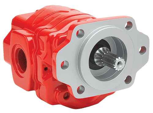
The external gear pump technology is a type of positive displacement pump. External gear pumps simply use the actions of gears to transfer different types of fluids. In this article, we will illustrate the main features of external and internal gear pumps, the way they work, and other technical information. Finally, we will briefly introduce the external gear pumps produced
• an external gear pump utilizes two identical gears meshed side by side, where one gear (driving) is driven by a motor, and it – in turn – drives the other one, the idle (driven) gear. Each gear is supported by a shaft with bearings on both sides of the gear. Fluid trapped between the gear teeth is transported from the inlet to outlet ports, with the gear mesh acting as a seal between the ports.
• aninternal gear pumputilizes two meshing gears with the outer (ring) gear typically driving the inner (idler) gear. Fluids trapped between the gears are transmitted from the inlet to the outlet port due to the rotation of the meshing gears, with the gear mesh typically acting as a seal between the ports. An internal gear pump will often use a crescent component to assist in the internal sealing of the gears.
In the external gear pumps the two gears mesh with each other in a close fitting housing. As the gears rotate, fluid fills the space between corresponding gear teeth and is carried from the inlet side to the outlet around the external circumference of the gears. Where the teeth mesh together, fluid cannot pass and so it is ejected through the outlet.
• External helical gears: helical gears utilize “angled” gears, that is each gear tooth has an identical helix angle (referenced to the axis of rotation) such that the contact ratio of the gear mesh is always greater than 1. A higher contact ratio is beneficial in that two gears are often sharing the load during operation. Typically the helix angle for a pump gear is less than 5 degrees to maintain good hydraulic efficiency.
Thanks to their versatility, resistance, and technical features, external gear pumps offer advantagesthat are renowned in all their application fields.
Fluid-o-Tech is a market leader in the design and production of external gear pumpsand internal gear pumps. At the core of our work, we have chosen to build long-lasting relationships of trust with our Customers, becoming their technology partner for the newest developments.
Fluid-o-Tech external gear pump technology has proven to be the most reliable, efficient,and robustpump technology over the years for use within different applications and industries. Among our product types that are worth mentioning, you should consider:

Low Trip - Run the pump with the OUTLET valves closed. This is the minimum flow. Set the low trip about here. High Trip - Run the pump with all valves wide open. This is the maximum flow. Set the high trip about here.
:quality(90)/images.vogel.de/vogelonline/bdb/351100/351166/original.jpg)
For most normal size fixtures, a pump rated in gpm (gallons per minute) is not recommended. If your pump is rated much more than 1 gpm, call us, we’d rather give you sound advice now than have you damage clamps and have to buy replacements. Be sure that you do not exceed the recommended flow rates for your system. If you aren’t sure, ask us.
Call us. It can often be made to work. Some modifications will probably be necessary. If you have a VektorFlo® pump which runs continuously, call us immediately (they are not set up to run continuously).
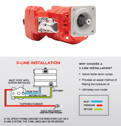
I’ve been using a dump pump (pump builds to pressure, shuts off and releases pressure automatically). Is this pump suitable for hydraulic workholding components?
Clamps should be positioned directly opposite a fixed locator, hydraulic support or other supporting element. This element may be a part of the fixture, a solid portion of a rigid part or a properly sized floating locator such as a hydraulic work support. If your clamp is putting force into your part which is not transmitted directly into a solid stop, it may distort the part. Clamping on draft angles or “mushrooming” the part with excessive force can also cause part distortion. Send us a print of your fixture design, we’ll be pleased to evaluate it and make suggestions.
There could be several causes: A “spool” valve when used with a demand pump will cause it to turn on and off as its internal leakage bleeds off pressure. Use of spool valves voids warranties on VektorFlo® pumps. We suggest the use of “zero leak” poppet or shear seal type valves.
Industrial type double acting cylinders (even high quality ones not designed for clamping) have significant leakage across their internal seals. This leakage will not normally be externally visible. Internal leaks from one side of the piston to the other will cause pumps to cycle excessively.
All leaks at fittings, seals or other typical leak points will eventually cause a pump to cycle. If your VektorFlo® pump cycles more often than you feel appropriate (more than once per minute without a valve being shifted) call us. We will gladly offer advice.
We do not recommend it. Our sequence valves operate better if run directly from the main hydraulic supply line and set at different pressures. (We recommend at least 500 psi differential for ease of set-up.)
Yes, our warranty specifically excludes the use of non-standard hydraulic fluids. While there are some good fluids out there, we have a list of approved fluids (or equivalent). If you must use another fluid and it has good lubricity and corrosion resistance, we can tell you whether it is likely to cause problems or not. Some fluids may provide adequate long term service, we will offer advice upon request. We do not approve of the use of these fluids but may be able to recommend compatible seals.
Preventive maintenance. Before you store your fixtures, be sure that they are free of coolants, coolant buildup, clean and dry. A light coating of corrosion protection may help. Be sure to store in a cool, dry, clean environment. We encourage the use of double acting clamps on fixtures which will be stored for extended periods.
When I unclamp my single acting clamps, a “squirt” of coolant comes out of the vent port. I am running flood coolant and the clamps are covered during the entire machine cycle. Can I eliminate this problem?
Maybe. We suggest you run a vent line to fresh air from each breather port. This can be done in copper or plastic tubing. If you can’t get to fresh air, a trap in the tubing or protected vent inlet area will reduce the amount of coolant entering the cylinders. Keeping the coolant out will reduce the chance of corrosion in the cylinders. It will also keep the cylinders from having to expel the coolant as they return causing sluggish return. Our swing clamps are now available with “bottom” venting to allow them to breathe dry air from protected areas under the fixture.
Water-glycol is a nontraditional hydraulic fluid. This fluid was developed for use where petroleum based fluids are not allowed. They are commonly used in areas requiring “flameproof” fluid. They often cause problems with device seals, valves and pumps. We do not recommend water-glycol fluids. We may in some cases be able to provide devices with seal compounds acceptable for use in this environment. We cannot recommend or warrant their use in any Vektek pump or directional control valve.
Anything above 350°F is considered too hot for most hydraulic fluids and seals. Our standard seals are rated to operate at temperatures from 40°F to 160°F. Even seals made of Viton® (fluorocarbon) are not recommended above 350°F. For advice on high heat applications, you may contact Vektek’s Engineering Department.
A “breather” is a port designed to let captured air vent to atmosphere when a cylinder is actuated or a work support plunger is moved. This lets the trapped air “breathe” into the room. Breathers will sometimes “inhale” coolant and it is often preferable to plumb them to clean, dry air space rather than allow them to suck coolant. Vektek cylinders are all designed with stainless steel springs to reduce the possibility of corrosion from this coolant contamination. Cylinder malfunction wiil occur if breathers are plugged.

A Positive Displacement pump (PD pump) is a mechanical device which displaces a known quantity of liquid for every revolution or cycle that the pump completes. The flow rate through a positive displacement pump is directly proportional to its speed and number of cycles over a given time.
A positive displacement pump works by using a screw, a blade, a vane, a lobe, a gear or diaphragm. It creates a chamber or cavity between the pumping elements and the cavity in which the fluid is temporarily stored is moved by the reciprocating or rotary motion along the pipe to its destination.
Progressive Cavity Pump has a rotor rotating within a housing called a stator. The rotor is always metallic and the stator is made up of a rubber type of material. It looks somewhat like a screw thread – the fluid is between the cavities and the rotary motion of the rotor forces the fluid through from one end to the other. It has a low to moderate capacity, low to high pressure, good solids handling capability, one seal, low shear, constant flow and a low pulsation.
Rotary Lobe Pumphas moderate to high capacity, low to moderate pressure, good solids handling capability, two/four seals, a constant flow and moderate pulsation.
Screw Pump –the screw pump has multi versions known as multi screw pumps featuring moderate to high capacity, high pressures, only lubricative liquids, no solids handling capability, one seal and a constant flow.
Diaphragm Pump – Air Operated Diaphragm Pump has low to moderate capacity, low to moderate pressure, very low efficiencies, no seal and high pulsation.
Positive Displacement pumps are generally used for fluids with a relatively high viscosity. They can be used where high accuracy is required e.g metering or dosing. They can also be used where high pressures are required i.e high pressure washing. Waste Water Treatment is another application e.g Netzsch Tornado Rotary Lobe Pump
The main advantages of a Positive Displacement Pump is that it can handle highly viscous fluids whereas a Centrifugal Pump would be inefficient and require high driver powers. PD pumps also have a good volumetric efficiency & driver power is kept to a minimum. The flow rate is easily adjustable via a speed control because the flow rate is directly proportional to its speed. Driver sizing is not as critical as with a Centrifugal pump because the pump will deliver the known quantity of fluids regardless of system back pressure (losses). A Positive Displacement Pump can produce a very low shear action in the case of sensitive fluids.
The main disadvantages of a Positive Displacement Pump vs a Centrifugal pump is that dry running can be catastrophic due to either close clearances of parts or in the case of progressive cavity pumps the interference fit between the rotor and stator. All PD pumps require the installation of a pressure relief valve to prevent failure of the pump or piping in case of accident or closure of the delivery valve or blockage in the piping. Main pd pumps will produce pulsations which can lead to undesirable effects i.e vibration, product damage & water hammer. PD pumps have a limited flow range ~1000m³/hr vs 180,000m³/hr Centrifugal Pumps. The material of construction of PD pumps are more limited in range of available materials than that of Centrifugal Pumps and finally PD pumps have limited solids handling ability in terms of size and/or content.
A Positive Displacement Pump will usually self-prime due to the very small clearances which exist within the pump. This will help it pull a vacuum and thus expel the air through the pump until the liquid reaches the pump. Care should be taken on the suction line i.e installation of a “goose neck” which will ensure there is some liquid in the pump during the priming cycle which will prevent dry running & consequently failure.
An Air Operated Diaphragm pump (AODD pump) is able to self-prime without any liquid being present but this capability to lift is limited if the line is empty of fluid.
Certain Positive Displacement Pumps can run dry i.e Air Operated Diaphragm pumps have no parts requiring lubrication or no close clearances between parts. Peristaltic pumps can run dry as the hose is lubricated in a bath of its own fluid. Other types of PD pumps should not be run dry.
Every pump has a NPSH (Net pressure suction head) required to ensure reliable and trouble-free operation without damage caused by cavitation therefore therefore the system should be designed to ensure there is a sufficient margin between NPSHA (Net pressure suction head available) and NPSHR (Net pressure suction head required).
Unlike a centrifugal pump which produces pressure, a positive displacement pump does not produce pressure – it is the system itself that develops pressure from the pressure drop which then creates a back pressure which largely depends on the flow rate through the system i.e higher flow rates will result in higher losses and as a result a higher back pressure. The back pressure is also dependent on the pressure in the vessel at the point of discharge i.e a hydrogen blanket present or steam. The pressure is controlled largely by the pumping rate, therefore, pressure is controlled by varying the speed of the pump. In cases where the variable speed drive is not deployed the system pressure will be controlled to a degree by the setting of the pressure relief valve.
Positive Displacement Metering pumps are usually used where a high degree of accuracy is required e.g in dosing applications where pH control is required e.g Waste Water Treatment Plants or where filling lines require accuracy of volumes of fluid dispersed into containers.
Flexachem are the leading distributors for Netzsch Positive Displacements Pumps in Ireland – Progressive Cavity Pump, Rotary Lobe Pump (Industrial applications) & Screw Pump. We also supply Inoxpa Sanitary Rotary Lobe Pump and Flotronic Air Operated Diaphragm Pumps for the Food & Beverage & Pharma sectors.
We provide localised technical support & on-site service engineering to support the operational needs of our clients. We also hold a heavily stocked inventory to help take the pressure off you in the event of unexpected emergencies. Why not contact one of our Pump Specialists if you have a particular application in mind.

One of the more challenging aspects of developing pasture and grazing land is providing access to a reliable water supply for livestock. In some cases, existing streams, creeks, or ponds provide drinking water for the livestock. When a surface water source is not available, wells can be drilled and pumps installed to provide water for the animals. In some instances, surface water may be available, but not accessible to the livestock due to water quality issues, steep access slopes, or fencing issues.
Providing an electrical power source to such a location for a pump can be cost-prohibitive. Utilizing a pump powered by an internal combustion engine can require inspection and attention several times each day and regular fuel supply runs. Nose pumps and sling pumps may be used effectively in some of these situations, but these pumps will not work if the elevation difference between the water source and grazing area is greater than twenty feet. Solar-powered pumps are an excellent option but can be expensive depending on the flow rate and pressure needs of the system.
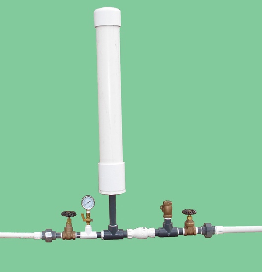
Figure 1. A 3/4-inch homemade hydraulic ram pump made with PVC fittings. Water flows from right to left during operation. Image credit: W. Bryan Smith, Clemson University.
One possible solution to providing livestock drinking water in remote locations is the hydraulic ram pump. The first development work of the hydraulic ram is reported to have been completed by John Whitehurst in 1772, with the first automatic version of the hydraulic ram developed by Joseph Montgolfier in 1796.1 Various companies in England and the United States have been producing cast-iron versions of the hydraulic ram since the early 1800s. Hydraulic ram pumps can lift water over a considerable elevation, and do not require any external power source.
Commercially sold hydraulic ram pumps last for decades but are quite expensive. A simple, homemade PVC (polyvinyl chloride) hydraulic ram pump (figure 1) may be constructed for $150 to $200 depending on material costs in your area and size of pump constructed. These homemade pumps will last for several years if not longer and can allow a farmer to see how such a pump would work before investing in a more expensive commercial unit.
Hydraulic ram pumps operate by utilizing pressure developed by a “water hammer” shock wave. Any object in motion has an inertial force. Energy is required to place the object in motion, and energy will also be required to stop the motion, with more energy being required if the motion is started or stopped quickly. A flow of water in a pipe also has inertia (or momentum) that resists sudden changes in velocity. Slowly closing a valve allows this inertia to dissipate over time, producing very little pressure increase in the pipe. Closing a valve very rapidly will create a pressure surge or shock wave as the flowing water stops, which moves back up the pipe – much like a train stopping, with individual train cars hitting the coupling in front of them in rapid succession as the brakes are applied. The more quickly the valve is closed, the larger the shock wave produced. A faster water flow will also produce a larger shock wave when a valve is closed, since more inertia or momentum is involved. A longer pipe will also produce a larger shock wave for the same reason.
A hydraulic ram relies on a non-pressurized flow of water in a pipe placed from the water source to the pump (called a “drive” pipe). This flow is produced by placing the hydraulic ram some distance below a water source and running the drive pipe from the water source to the pump. The hydraulic ram employs two check valves, which are the only moving parts in the pump.
Figure 6. Step 5: When the low-pressure wave reaches the drive pipe inlet, a normal pressure wave travels down the drive pipe to the valves. Normal water flow due to the elevation of the source water above the ram follows this pressure wave, and the next cycle begins. Image credit: W. Bryan Smith, Clemson University. The hydraulic ram pump cycle described in figures 2-6 may repeat from forty to ninety times per minute depending on elevation drop to the hydraulic ram pump, drive pipe length from the water source to the ram pump, and drive pipe material used. Image credit: W. Bryan Smith, Clemson University.
Figure 7. A typical hydraulic ram pump installation, with (a) drive pipe, (b) delivery pipe, and (c) hydraulic ram pump placement noted. Image credit: W. Bryan Smith, Clemson University.
In its simplest form, a hydraulic ram pump installation includes a drive pipe to bring water from the water source to the pump, the hydraulic ram pump, and a delivery pipe to take water from the pump to the water trough or site where water is needed (figure 7).
The drive pipe size determines the actual pump size and also determines the maximum flow rate that may be expected from the pump. Since the pump efficiency depends on capturing as much of the water hammer shock wave as possible, the best drive pipe material for a hydraulic ram pump installation is galvanized steel pipe. Most livestock producers use PVC pipe instead due to the lower cost and the difficulty in placing and assembling galvanized steel pipe. Hydraulic ram pump installations using a PVC drive pipe will work well, but the elasticity of the pipe will allow some of the water hammer shock wave to dissipate slightly with pipe wall expansion. If PVC pipe is used for the drive pipe installation, choose PVC piping with a thicker wall. Schedule 80 PVC pipe would be the better choice, with Schedule 40 PVC pipe being a secondary choice.
The best drive pipe installation would place the pipe on a constant slope from the water source to the hydraulic ram pump, with no bends or elbows, and anchor it with bolts and/or galvanized tie-downs to large rocks or concrete pads to prevent movement. This would allow the most efficient shock wave development. The Gravi-Chek Company suggests the optimum drive pipe slope is one foot of drop for every five feet of length, which corresponds to a 20% slope.2 However, this is not always practical in livestock water supply installations. The ram pump will work with piping that is not installed on a constant slope, as long as all piping slopes are either level or downward toward the pump (figure 8). There can be no “humps” or up-and-down installation points in the drive pipe, since this will allow air to be captured in the pipe, which will allow shock wave dissipation.
Figure 8. A PVC drive pipe placed in a stream bed. Galvanized steel was not an option due to the bed topography and geometry. The hydraulic ram pump worked well, but each bend allowed a tiny portion of the shock wave to dissipate. A straight, galvanized steel pipe would have captured a larger shock wave and provided more pressure. Image credit: W. Bryan Smith, Clemson University.
If a choice must be made between installing the drive pipe on a constant slope and using a more rigid drive pipe (such as galvanized steel), choose the more rigid drive pipe. This will have a larger impact on pump performance than the drive pipe slope.
There is a range of allowable drive pipe lengths for each pipe size used. If the drive pipe is too short or too long the pressure wave that allows the pump to cycle will not develop properly.
The publication Hydraulic Rams for Off-Stream Livestock Watering gives the following equations developed by N. G. Calvert for minimum and maximum drive pipe length.3
Rife Ram Company literature offers a different method of drive pipe length selection.4 The Rife method does not consider pipe size but is based solely on vertical elevation drop or fall from the water source to the hydraulic ram pump. Values are presented in table 2.
Figure 9. A hydraulic ram pump installation with a (a) standpipe and (b) supply pipe to allow a longer piping solution from water source to ram pump location. Image credit: W. Bryan Smith, Clemson University.
The Rife recommendations in table 2 maintain a given pipe slope for each range of elevation falls. Either method (table 1 or table 2) may be used to determine mainline length; satisfying both methods may provide the best ram pump performance.
There are installation solutions if the maximum drive pipe length allowed is not long enough to reach the water source from the hydraulic ram pump placement. One option is to install a “standpipe” at the maximum drive pipe distance from the ram pump (figure 9). This standpipe should be three pipe sizes larger than the drive pipe and should be open at the top to allow the water hammer shock wave to dissipate at that point. The standpipe should be installed vertically, with the top of the standpipe a foot or so above the level of the water source. Supply piping, which should be at least one pipe size larger than the drive pipe, is then run from that point to the water source.
Figure 10. Use of a carpenter’s level and a measuring stick to determine elevation drop from the water source to the proposed hydraulic ram pump location. Image credit: W. Bryan Smith, Clemson University.
Hydraulic ram pumps operate based on an amount of elevation drop or fall from the water source to the site where the ram pump is placed. The amount of drop will determine the performance of the ram pump. The amount of drop or fall available at a given location can be measured using a measuring stick and a carpenter’s level. Start at the site where the hydraulic ram pump will be placed. Hold the measuring stick vertically, placing one end on the ground. Place the carpenter’s level on the measuring stick, holding it level, with the top even with the top of the measuring stick. Look along the top of the carpenter’s level at the slope going up to the water supply, and sighting along the top of the level, pick a spot on the slope (figure 10). That point is the height of the measuring stick above the starting point. Move to that spot and repeat the sighting process, continuing up the slope after each sighting until the water supply is reached. Count the number of times the measuring stick was placed on the ground, multiply that number by the measuring stick’s length, add any partial stick measurement for the last sighting (see figure 10), and the result will be the elevation drop or fall from the water source to the ram pump location.
Hydraulic ram pumps are very inefficient, generally pumping only one gallon of water for every eight gallons of water passing through the ram. They will, however, pump water up ten feet (or more in some cases) of vertical elevation for every foot of elevation drop from the water source to the hydraulic ram. For instance, if there is an elevation drop of seven feet from the water source to the hydraulic ram, the user can expect the hydraulic ram to pump water up to seventy feet or more in vertical elevation above the ram. Higher delivery elevations do decrease the pump flow – the higher the elevation difference between the hydraulic ram and the delivery pipe outlet, the smaller the delivered water flow will be.
In this equation, Q is the available drive flow in gallons per minute, F is the fall in feet from the water source to the ram, E is the elevation from the ram to the water outlet, and D is the flow rate of the delivery water in gallons per minute. 0.6 is an efficiency factor and may differ somewhat between various ram pumps. For example, if a flow rate of twelve gallons per minute is available to operate a ram pump (Q), the pump is placed six feet below the water source (F), and the water will be pumped up an elevation of twenty feet to the outlet point (E), the amount of water that may be pumped with an appropriately-sized ram pump is:
The same pump with the same drive flow will provide less flow if the water is to be pumped up a higher elevation. For instance, using the data in the previous example but increasing the elevation lift to forty feet (E):
The pump inflow rate, Q, will always be determined by the drive pipe size, drive pipe length, and the elevation of the water source above the hydraulic ram.
Table 3 uses the Rife equation to list some flow rate ranges for various sizes of hydraulic ram pump based on the friction loss found in Schedule 40 PVC pipe. The pump flow ranges in the chart are based on a fall (F) of five feet of elevation and an elevation lift (E) of twenty-five feet. Changing the values of E or F will change the expected performance of the ram pump.
Some of the delivery flow rates listed in table 3 are quite small, but even the 3/4-inch ram pump will deliver a considerable amount of water over time. Hydraulic ram pumps operate twenty-four hours per day, seven days per week, so even at the minimum pump inflow the 3/4-inch ram pump will provide (0.10 gpm x 60 minutes x 24 hours =) 144 gallons of water per day, which would supply the daily water need of four to five 1,200 pound cattle.
If more flow is desired, either a larger hydraulic ram may be used, or another hydraulic ram may be installed with a separate drive pipe, and then plumbed into the same delivery pipe to the water trough as long as there is sufficient water flow in the water source to supply this demand.
Figure 11. A schematic diagram for homemade hydraulic ram pump Design 1. Table 4 contains item descriptions. Image credit: W. Bryan Smith, Clemson University.
There are a number of designs for a homemade hydraulic ram. The University of Warwick has some excellent designs developed for use in developing countries where standard plumbing parts may not be readily available.5
This publication will address two similar designs. The first design was developed by Mark Risse of the University of Georgia and was presented by Frank Henning in University of Georgia Extension Service publications #ENG98-0023 and #ENG98-003.6 Figure 11 provides a schematic of the design, and table 4 provides a parts list for a 1 1/4-inch hydraulic ram pump.
This is a very simple design that only requires assembly of basic plumbing fittings. The air chamber (#14–16) acts like a pressure tank for a well, using compressible air captured in the tank to buffer shock waves and provide a steady outlet pressure. The air initially captured in this air chamber, however, will be absorbed by the water flowing through the pump over time. When this happens there will be a much more pronounced shock to the pump and piping during each cycle (this condition is described as a water-logged pump), and material fatigue and failure will follow. In order to keep air in the chamber over time, a bicycle or scooter inner tube may be filled with air until it feels “springy” or “spongy,” and then folded and inserted into the pressure chamber before the cap (#16) is glued on to the pipe. This will retain air in the chamber and prevent pump failure.
Fittings 1–4 in the diagram must be the same size as the drive pipe in order for the pump to work properly. The spring-loaded check valve (#5) and the pipe nipple (#12) should also be the same size as the drive pipe, but the pump should work if they are reduced to the same size as the delivery pipe.
Figure 12. A brass swing check valve. Note the free-swinging flapper in the outlet port. The swing check valve should be placed vertically for best pump performance. Image credit: W. Bryan Smith, Clemson University.
Valve #1 in figure 11 is used to stop or allow flow to the pump and can be used to turn off water flow if the pump needs to be removed or serviced. Valve #7 is turned off while the pump is started, then gradually opened to allow water to flow after the pump is operating. The pump will operate for thirty seconds or more with this valve completely closed, and if the valve is left in the closed position the pump will reach some maximum pressure and stop operating. The ram pump requires approximately 10 psi of back pressure to operate, so if the delivery pipe outlet is not at least twenty-three feet above the ram pump, valve #7 can be used to throttle the flow and maintain the required back pressure.
The pressure gauge (#11) is used to determine when valve #7 may be opened during pump start-up and can be used to determine how much valve #7 should be closed during normal operation if throttling is needed. The pipe cock (#10) is optional but can be turned off to protect the gauge from failure over time due to repeated pulses.
The air chamber size is dictated by the expected flow rate of the hydraulic ram pump. University or Warwick documentation suggests the optimum pressure chamber volume is twenty to fifty times the expected volume of water delivery per cycle of the pump.5 Table 5 provides some minimum lengths of piping required for a pressure chamber based on this information. The table is based on a hydraulic ram that will operate sixty pulses or cycles per minute.
The second design presented in figure 13 is one commonly found on the internet in YouTube videos.7 It is very similar to the first design, but this design incorporates a homemade “snifter” valve that allows a small amount of air to be added to the air chamber with each pumping cycle, which eliminates the need for an inner tube in the air chamber.
Figure 13. A schematic diagram for homemade hydraulic ram pump Design 2 with air snifter. Tables 4 and 6 contain item descriptions. Image credit: W. Bryan Smith, Clemson University.
The size of the snifter hole is critical to pump operation. The University of Warwick has an extensive discussion concerning this property in their hydraulic ram pump documentation.5 Their information suggests drilling a 1/16-inch hole and increasing the size slightly if necessary. A 1/8-inch snifter hole or smaller with an appropriately sized cotter pin inserted may be a good option instead as a starting point. If the hydraulic ram should become waterlogged, a slightly larger snifter hole may be needed.
The advantage of this design is that if the snifter hole is sized correctly, the pump should never become waterlogged due to a leaking inner tube in the air chamber. The disadvantages are the trial-and-error approach to obtaining the correct hole size, the need for additional support for the pump’s increased vertical height, and the possibility that the snifter hole, being very small, may freeze over and close in cold weather.
Figure 14. A 3/4-inch hydraulic ram pump (Design 1) in operation. The image was taken just at waste valve closure. The concrete block is in place to support the air chamber. Image credit: W. Bryan Smith, Clemson University.
Both pump designs are started using the same steps. Attach the assembled ram pump to the drive pipe, close valve #7, then open valve #1 to allow water flow. The waste valve (#4) will almost immediately forcefully close. The flapper in the waste valve must be pushed down manually a number of times to initially start automatic pump operation. This process purges air from the system and builds up the pressure in the air chamber required for the pump to operate. Pressing the flapper down twenty to thirty times is expected to start a ram pump. If the pump does not start operating after pressing the flapper down more than seventy times, there is an issue somewhere in the system. The flapper on a smaller pump (1/2-inch, 3/4-inch, etc.) can be pressed down with a thumb fairly easily, but larger pumps may require the use of a metal rod of some type to push the flapper down, especially if there is considerable elevation drop between the water source and the hydraulic ram pump.
After the pump has started operating (figure 14), gradually open valve #7 to allow water to flow uphill to the water trough. The pump must have 10 psi or more back pressure to operate, so gradually open valve #7 while watching the gauge to maintain 10 psi of back pressure. Pressure will build as the water fills the delivery pipe as it is pumped uphill.
The pump will operate continuously after starting as long as water flows freely to the pump and is flowing out of the delivery pipe. If water flow is stopped at the water trough, the ram will pump up to some maximum pressure and stop, and then must be manually restarted. The pump will not restart itself. This means that if water is supplied to a single water trough, a float valve cannot be used. Some provision must be made to drain overflow away from the trough after it fills, since the water must flow continuously for the pump to remain in operation. A simple gravel-filled trench or another method may be used to direct the excess water away from the water trough.
Since water continuously flows out of the pump’s waste valve, some consideration must also be given to water drainage at the pump site. If the pump is placed near a stream downstream of a pool or other water source, this will not be an issue. If, however, it is placed on dry ground away from the water source, drainage must be considered.
There are no restrictions on the size or type of delivery pipe used beyond normal piping design practice. Galvanized steel pipe, PVC pipe, rubber hose, or a simple garden hose may be used to deliver water to the water trough, provided it is sized to deliver the anticipated flow rate. Some ram pump installation guidelines indicate the delivery pipe should be one half the size of the drive pipe, but this has no bearing o


 8613371530291