
running hydraulic pump dry in stock

Dry running a pump can cause all kinds of serious problems, yet many operators are unaware of the dangers. When a pump runs dry, it generates heat and force it was never designed to handle, leading to wear and tear that can quickly add up to inflated repair costs. Avoiding dry running is highly important, but it makes sense to learn how negative it can be in order to fully understand the severity of the phenomenon.
When a pump runs dry, it runs without any liquid going through it. This is always a bad idea, as it puts an inordinate amount of strain on the pump’s moving parts.
Instead of circulating fluid, a dry running pump pushes nothing but air around, leading to friction, heat, and destruction of delicate internals. A hydraulic pump is normally designed to run while filled with fluid. As it runs, the fluid inside it helps to preserve its internal pieces, cooling them and even assisting in centreing moving elements such as the rotor.
Pumps that operate at particularly high pressure can suffer considerable cavitation simply from fluid-derived vapor; completely dry running a finely tuned pump is significantly worse for its longevity. Even self-priming pumps should only be run once the proper amount of fluid is inside, as they can withstand only partial dry conditions while priming themselves.
Running your hydraulic pump dry is likely to result in disaster, wearing it out prematurely via the aforementioned heat, violent vibrations, or complete lock-up/seizure of important parts, costing you money to fix or replace.
Running a hydraulic pump dry can lead to a large variety of issues with the pump’s parts and the rest of your hydraulic system as well. Here are a few common problems that dry running can cause:
High temperatures caused by dry running can ruin your pump, pitting its housing and causing leaks.¹ If heat and pressure are excessive enough, the housing boss may deform, potentially stopping your impeller from rotating freely and rendering your pump functionally useless. In many cases, a severely damaged, leaking pump is likely to need replacing, which can run your costs up much further than anticipated.
As is the case for the housing of your pump, the impeller is susceptible to damage done by excessive heat during use. Dry running your pump causes friction, and this friction is strong enough to heat up the impeller, causing it to melt.² Even minor melting is severely detrimental to your pump’s performance, potentially causing it to seize up and stop working at all. Taking it apart for repair is usually an involved and costly exercise best avoided through preventive operating practices.
Internal wear caused by dry running your pump can lead to additional wear throughout the entirety of your system. This is generally caused by either excessive heat or metal particles scraped from disintegrating moving pieces within your pump travelling through the rest of your system. Metal particles, in particular, can cut and clog valve components, pipes, and tubes, leading to system failure over time.
You may need to run your pump dry for short periods of time to empty the system completely, but it is best to keep such instances as brief as possible. Once your tank or system has been emptied by the pump, it should be turned off. Do not allow it to keep running for more than a minute without any fluid.
Keeping someone in charge of monitoring your pump as it runs can help avoid unintended dry running problems. Often, a pump may be left running until a job is completed. If the pump performs its function faster than intended and all fluid is purged from the system, it will run dry and damage itself until an operator returns to turn it off. Having someone manage the pump at all times is crucial to keeping it functional.
Some companies have found an automatic means of controlling their pumps’ functions from afar. By leveraging special protective devices and control systems, it is possible to automatically stop a pump that is in danger of running dry, preserving its internal parts and averting expensive disasters.³ However, such devices incur an additional cost.
At White House Products, Ltd., we offer all manner ofpump parts to patch up a system damaged by dry running. We can also provide complete replacements as needed. Call our technical support team at +44 (0)1475 742500 to learn how we can help get your pump working again.

Dry running occurs when a pump operates without adequate liquid. This leads to a surge in pressure, flow or overheating that will instigate a pump failure. As a result, the pumping elements seize up on the shaft. This article explains how the problem can be avoided.
Pump cavitation and dry run related failures cost companies millions of dollars annually, including replacement costs for damaged equipment and lost sales due to poor performance. With an improving economy and anticipated fuel production increase, sales of fluid-handling pumps are forecast to rise 5.5% annually to $84 billion in 2018.
When cavitation occurs, vapour bubbles form and expand in the pumping liquid on the suction side of the pump before reaching the higher-pressure discharge side of the pump and violently collapsing near the surface of the pumping element. This triggers shock waves inside the pump which cause significant damage to the pumping element.
If left untreated, cavitation will destroy the pumping element and other components over time, drastically shortening the pump’s life. Cavitation may also cause excessive vibration leading to premature seal-and-bearing failure, in addition to creating an immediate increase power consumption and decrease in flow and pressure output.
Whereas cavitation is a common cause of pump degradation and failure related to the physics involved in the pumping operation, dry running on the other hand is usually related to how pumps are actively operated by end users. Cavitation itself may also be so widespread that it creates a dry run situation inside the pump due to excessive vapour formation. Pumps most often rely on the pumping fluid itself to lubricate the bearing surfaces of the pumping element. If a pump is operated without this fluid, the low to non-existent lubrication at these bearing surfaces will cause excess heat generation, increased wear, and potentially even failure of the pump if the pumping element seizes or breaks. The life of a pump subjected to dry run will be significantly reduced or, in the worst case, brought to an untimely end.
The most immediate cause of dry running is usually human error. Companies rely on operators to monitor pumps, but problems occur in cases where operators unintentionally leave pumps running over a period of time after the pumping operation is complete. For example, after offloading is complete, a transfer truck driver may leave a pump running unattended, unaware that the pump is still running. This continued operation after all pumping fluid has been transferred will create a dry run condition inside the pump, leading to damage from this lack of lubrication. Such a situation may also occur during pump priming, where the pipe system and pump casing have not yet been filled with fluid and the pump runs dry until the priming period is over.
In response, many companies have installed protection and control devices of various designs which stop the pump immediately after the pumping operation is complete, preventing dry running from occurring. Engineers also spend significant time and effort to ensure pumps are properly set up for priming, increasing the cost and complexity of plumbing. This level of protection comes at a significant expense. Despite an operator’s best efforts, harmful events still may occur from malfunctioning monitoring systems, improper use of control equipment, or unpredictable events. Pump owners specifically desire a technology to prevent the damaging results of dry running so they are not dependent on operators as their only line of defense. In addition to protection against dry running, pump specifying engineers and maintenance personnel are always in search of a solution to prevent the ever-present problem of cavitation in the most demanding pump applications, with the hopeful result of reduced maintenance costs and increased throughput.
Parker engineers have developed dual-stage hybrid technology by incorporating a centrifugal pump as a first stage in front of a positive displacement rotary tri-lobe pump as a second stage. This dual-stage hybrid approach boosts the flow through the centrifugal impeller, elevating the pressure of the fluid charge for the second stage tri-lobe rotors. In effect, the centrifugal impeller feeds the rotary lobe stage virtually eliminating cavitation issues common in ordinary positive displacement pumps.
The company’s patent-pending, tri-lobe rotors and wiper blade seals are the key to the pump’s dry run capabilities and dry suction capacity. They are pre-loaded against the internal pump casing walls and produce vacuum to 27 inches of mercury. This allows the pump to self-prime, avoiding any dry priming or vapour lock issues common in ordinary centrifugal pumps.
Oil and gas industry operators have raised their voice to solve their top failure modes: extremely short or non-existent dry run time limits and unacceptable levels of cavitation when pumping extremely light liquids with high vapor pressures. Applications which have required two or three different pumps to fully address can now be served by a single product.

Did you know you can invalidate the warranty of your final drive motor if you make the mistake of dry starting it after you’ve just installed it? Read on to learn what a dry start it, how it can damage your motor, and how to keep it from happening to you.
Many people mistakenly believe that because hydraulic fluid circulates through the hydraulic system that all you need to do is connect the hoses to the right ports and you’re good to go. Just because the hydraulic fluid circulates doesn’t mean you can attach an empty component and expect it to be ready to run. And frankly, there is no excuse for dry starting the planetary side of a final drive motor because there is no circulation of fluid to fall back on.
That damage can lead to flakes and other tiny bits of metal breaking free and contaminating the hydraulic fluid or oil once it has access to these parts. Then you have
Scratches and abrasions lead to a reduction in performance, which means that a brand new final drive motor ends up with compromised efficiency and power from the start. In short, you’ve damaged the motor immediately after installation, and dry start damage is not covered by warranties.
Before starting a hydraulic motor that is either brand new, repaired, or rebuilt, add clean, new hydraulic fluid to the hydraulic hub and make sure there is fresh gear oil in the planetary hub. That is all you need to do in order to avoid a dry start.
Just a few simple steps can help you avoid damaging your final drive hydraulic motor by dry starting it. Since damage caused by a dry start is not covered by warranty, it is all the more important that you make sure your motor has fluid and gear oil before you start it.
is your partner in providing new or remanufactured final drive hydraulic motors from a single mini-excavator to a fleet of heavy equipment. Call today so we can find the right final drive or hydraulic component for you, or check out our online store to.

In a recent 2021 Fluid Power Technology Conference — Virtual Series presentation, MSOE University’s Tom Wanke took an in-depth look at Pump and Motor Troubleshooting, Failure Modes and Analysis. One problem that drives engineers and maintenance technicians crazy is when a hydraulic pump underperforms or runs erratically, but doesn’t completely fail. Sorting out the root cause requires a systemic and meticulous approach to troubleshooting, said Wanke. When a pump is delivering some flow, but less than normal, here are nine possible culprits.
Aeration. Fluid aeration and cavitation (discussed below) are considered system faults, as they can be caused by various factors and conditions not related to the pump. Gas bubbles will form due to separation of dissolved air, oil evaporation or entrained air. Bubbles will be transported with the oil to the delivery side of the pump. Bubbles can be sustained in the system if they are formed early enough to grow in size, or if pressure at the delivery side of the pump is relatively low. This is called aeration.
There are many ways air gets into a system. For instance, if there is a leaking fitting in the intake line, tighten it. If the suction hose is porous or has a pin-hole leak, replace it. Likewise, if the pump shaft seal is worn or damaged, install a new seal.
Cavitation. If gas bubbles in the system, described above, implode at the delivery side of the pump at high pressure, this is called cavitation. It can cause high impact forces and severe erosion damage to the components.
Pump undersized. While it may seem obvious, check that you’ve installed the right pump. Make sure you have the correct size pump and proper displacement.
Wrong volume control. Is it a variable-displacement pump? Be sure that the pump is set to deliver the proper flow, and that the volume control is operating properly. Check the pump controller setting and, if necessary, reset the controller to the required value.
Internal leakage or contamination. If the pump delivers low or erratic flow, in addition to other causes listed here, perhaps the pump’s internal parts are sticking. Dissemble, clean and repair; and make sure no varnish or sludge is in the oil. If you suspect excessive wear, conduct a pump performance test and, if necessary, rebuild or replace the pump.

Facility operators in the oil and gas industry have raised concerns on how to solve their top failure modes: extremely short or non-existent dry run pump time limits and unacceptable levels of cavitation when pumping extremely light liquids with high vapor pressures.
Pump cavitation and dry run related failures cost companies millions of dollars annually, including replacement costs for damaged equipment and lost sales due to poor performance. With an improving economy and anticipated fuel production increase, sales of fluid-handling pumps are forecast to rise 5.5% annually to $84 billion in 2018. Given this proliferation, the historical pattern suggests that costs associated with repairs or replacements also will increase dramatically.
Learn how Parker"s innovation in pump technology can reduce your operational downtime, decrease operating costs, and improve performance. Download our white paper now.
Dry running occurs when a pump operates without sufficient lubricating liquid around the pumping element. This can be caused by either widespread vapor formation, also known as cavitation, inside the pump or absence of pumping fluid altogether. These adverse conditions can lead to dangerously unstable pressure, flow, or overheating which may cause the pumping element to seize or break.
When cavitation occurs, vapor bubbles form and expand in the pumping liquid on the suction side of the pump before reaching the higher-pressure discharge side of the pump and violently collapsing near the surface of the pumping element. This triggers shock waves inside the pump which cause significant damage to the pumping element. If left untreated, cavitation will destroy the pumping element and other components over time, drastically shortening the pump’s life.
Cavitation itself may also be so widespread that it creates a dry run situation inside the pump due to excessive vapor formation. Pumps most often rely on the pumping fluid itself to lubricate the bearing surfaces of the pumping element – if a pump is operated without this fluid, the low to non-existent lubrication at these bearing surfaces will cause excess heat generation, increased wear, and potentially even failure of the pump if the pumping element seizes or breaks. The life of a pump subjected to dry run will be significantly reduced or, in the worst case, brought to an untimely end.
“What separates our solution from our competitors is, our technology is automated and integrated into the pump design. You don’t need to worry about pumps stopping and starting every 20 – 30 seconds, they will dry run continuously.”
Learn how this innovation in pump technology can reduce your operational downtime, decrease operating costs, and improve performance. Download our white paper now.
Check that the electric motor is running. Although this is a simple concept, before you begin replacing parts, it’s critical that you make sure the electric motor is running. This can often be one of the easiest aspects to overlook, but it is necessary to confirm before moving forward.
Check that the pump shaft is rotating. Even though coupling guards and C-face mounts can make this difficult to confirm, it is important to establish if your pump shaft is rotating. If it isn’t, this could be an indication of a more severe issue, and this should be investigated immediately.
Check the oil level. This one tends to be the more obvious check, as it is often one of the only factors inspected before the pump is changed. The oil level should be three inches above the pump suction. Otherwise, a vortex can form in the reservoir, allowing air into the pump.
What does the pump sound like when it is operating normally? Vane pumps generally are quieter than piston and gear pumps. If the pump has a high-pitched whining sound, it most likely is cavitating. If it has a knocking sound, like marbles rattling around, then aeration is the likely cause.
Cavitation is the formation and collapse of air cavities in the liquid. When the pump cannot get the total volume of oil it needs, cavitation occurs. Hydraulic oil contains approximately nine percent dissolved air. When the pump does not receive adequate oil volume at its suction port, high vacuum pressure occurs.
This dissolved air is pulled out of the oil on the suction side and then collapses or implodes on the pressure side. The implosions produce a very steady, high-pitched sound. As the air bubbles collapse, the inside of the pump is damaged.
While cavitation is a devastating development, with proper preventative maintenance practices and a quality monitoring system, early detection and deterrence remain attainable goals. UE System’s UltraTrak 850S CD pump cavitation sensor is a Smart Analog Sensor designed and optimized to detect cavitation on pumps earlier by measuring the ultrasound produced as cavitation starts to develop early-onset bubbles in the pump. By continuously monitoring the impact caused by cavitation, the system provides a simple, single value to trend and alert when cavitation is occurring.
The oil viscosity is too high. Low oil temperature increases the oil viscosity, making it harder for the oil to reach the pump. Most hydraulic systems should not be started with the oil any colder than 40°F and should not be put under load until the oil is at least 70°F.
Many reservoirs do not have heaters, particularly in the South. Even when heaters are available, they are often disconnected. While the damage may not be immediate, if a pump is continually started up when the oil is too cold, the pump will fail prematurely.
The suction filter or strainer is contaminated. A strainer is typically 74 or 149 microns in size and is used to keep “large” particles out of the pump. The strainer may be located inside or outside the reservoir. Strainers located inside the reservoir are out of sight and out of mind. Many times, maintenance personnel are not even aware that there is a strainer in the reservoir.
The suction strainer should be removed from the line or reservoir and cleaned a minimum of once a year. Years ago, a plant sought out help to troubleshoot a system that had already had five pumps changed within a single week. Upon closer inspection, it was discovered that the breather cap was missing, allowing dirty air to flow directly into the reservoir.
A check of the hydraulic schematic showed a strainer in the suction line inside the tank. When the strainer was removed, a shop rag was found wrapped around the screen mesh. Apparently, someone had used the rag to plug the breather cap opening, and it had then fallen into the tank. Contamination can come from a variety of different sources, so it pays to be vigilant and responsible with our practices and reliability measures.
The electric motor is driving the hydraulic pump at a speed that is higher than the pump’s rating. All pumps have a recommended maximum drive speed. If the speed is too high, a higher volume of oil will be needed at the suction port.
Due to the size of the suction port, adequate oil cannot fill the suction cavity in the pump, resulting in cavitation. Although this rarely happens, some pumps are rated at a maximum drive speed of 1,200 revolutions per minute (RPM), while others have a maximum speed of 3,600 RPM. The drive speed should be checked any time a pump is replaced with a different brand or model.
Every one of these devastating causes of cavitation threatens to cause major, irreversible damage to your equipment. Therefore, it’s not only critical to have proper, proactive practices in place, but also a monitoring system that can continuously protect your valuable assets, such as UE System’s UltraTrak 850S CD pump cavitation senor. These sensors regularly monitor the health of your pumps and alert you immediately if cavitation symptoms are present, allowing you to take corrective action before it’s too late.
Aeration is sometimes known as pseudo cavitation because air is entering the pump suction cavity. However, the causes of aeration are entirely different than that of cavitation. While cavitation pulls air out of the oil, aeration is the result of outside air entering the pump’s suction line.
Several factors can cause aeration, including an air leak in the suction line. This could be in the form of a loose connection, a cracked line, or an improper fitting seal. One method of finding the leak is to squirt oil around the suction line fittings. The fluid will be momentarily drawn into the suction line, and the knocking sound inside the pump will stop for a short period of time once the airflow path is found.
A bad shaft seal can also cause aeration if the system is supplied by one or more fixed displacement pumps. Oil that bypasses inside a fixed displacement pump is ported back to the suction port. If the shaft seal is worn or damaged, air can flow through the seal and into the pump’s suction cavity.
As mentioned previously, if the oil level is too low, oil can enter the suction line and flow into the pump. Therefore, always check the oil level with all cylinders in the retracted position.
If a new pump is installed and pressure will not build, the shaft may be rotating in the wrong direction. Some gear pumps can be rotated in either direction, but most have an arrow on the housing indicating the direction of rotation, as depicted in Figure 2.
Pump rotation should always be viewed from the shaft end. If the pump is rotated in the wrong direction, adequate fluid will not fill the suction port due to the pump’s internal design.
A fixed displacement pump delivers a constant volume of oil for a given shaft speed. A relief valve must be included downstream of the pump to limit the maximum pressure in the system.
After the visual and sound checks are made, the next step is to determine whether you have a volume or pressure problem. If the pressure will not build to the desired level, isolate the pump and relief valve from the system. This can be done by closing a valve, plugging the line downstream, or blocking the relief valve. If the pressure builds when this is done, there is a component downstream of the isolation point that is bypassing. If the pressure does not build up, the pump or relief valve is bad.
If the system is operating at a slower speed, a volume problem exists. Pumps wear over time, which results in less oil being delivered. While a flow meter can be installed in the pump’s outlet line, this is not always practical, as the proper fittings and adapters may not be available. To determine if the pump is badly worn and bypassing, first check the current to the electric motor. If possible, this test should be made when the pump is new to establish a reference. Electric motor horsepower is relative to the hydraulic horsepower required by the system.
For example, if a 50-GPM pump is used and the maximum pressure is 1,500 psi, a 50-hp motor will be required. If the pump is delivering less oil than when it was new, the current to drive the pump will drop. A 230-volt, 50-hp motor has an average full load rating of 130 amps. If the amperage is considerably lower, the pump is most likely bypassing and should be changed.
Figure 4.To isolate a fixed displacement pump and relief valve from the system, close a valve or plug the line downstream (left). If pressure builds, a component downstream of the isolation point is bypassing (right).
The most common type of variable displacement pump is the pressure-compensating design. The compensator setting limits the maximum pressure at the pump’s outlet port. The pump should be isolated as described for the fixed displacement pump.
If pressure does not build up, the relief valve or pump compensator may be bad. Prior to checking either component, perform the necessary lockout procedures and verify that the pressure at the outlet port is zero psi. The relief valve and compensator can then be taken apart and checked for contamination, wear, and broken springs.
Install a flow meter in the case drain line and check the flow rate. Most variable displacement pumps bypass one to three percent of the maximum pump volume through the case drain line. If the flow rate reaches 10 percent, the pump should be changed. Permanently installing a flow meter in the case drain line is an excellent reliability and troubleshooting tool.
Ensure the compensator is 200 psi above the maximum load pressure. If set too low, the compensator spool will shift and start reducing the pump volume when the system is calling for maximum volume.
Performing these recommended tests should help you make good decisions about the condition of your pumps or the cause of pump failures. If you change a pump, have a reason for changing it. Don’t just do it because you have a spare one in stock.
Conduct a reliability assessment on each of your hydraulic systems so when an issue occurs, you will have current pressure and temperature readings to consult.
Al Smiley is the president of GPM Hydraulic Consulting Inc., located in Monroe, Georgia. Since 1994, GPM has provided hydraulic training, consulting and reliability assessments to companies in t...
Our submersible hydraulic water pump is more versatile and efficient than traditional electric pumps. These portable hydraulic water pumps utilize a highly efficient design to remove water quickly. Moreover, they can run dry and require no cooling while operating.
RGC offers Flow Dividers, allowing you to run RGC tools from an auxiliary power supply. We also offer additional supplies and accessories for our hydraulic water pumps, including hose whips, hydraulic hoses, and biodegradable hydraulic oil.
Questions about our hydraulic water pumps for sale? Reach out to us online by filling out our contact form, or call us at 800-831-5438. With over 75 years of experience in hydraulic tool manufacturing, we’re happy to help in any way we can. Our expert team will answer any questions and provide you with more information regarding our pump products and hydraulic tools.
A dead-head is caused when a centrifugal pump operates with no flow through the pump due to a closed discharge valve or blockage in the line. The pump is forced to circulate the pumped medium, causing the temperature to continually rise. As the fluid churns inside the pump it heats into a vapor. Once a vapor is created, any bushings or mechanical seals in the pump heat to the point that they begin to crack, shatter, score or compromise the elastomers - killing the pump.
When a centrifugal pump is dead-heading, it can lead to explosions, due to the energy being put into the liquid in the pump. Hydraulic overpressure and possible chemical reactions in the pump can also be caused by the overexertion of pressure.
Due to the water levels not reducing during a dead-head scenario, a water level sensor will not detect if dead-heading is occurring. Therefore, pumps need to be installed with a temperature or a flow measuring device.
It is possible to dead head a centrifugal pump for a very short time. No manufacturer will put time limit on this as every installation is different and they will not want to be held accountable if a failure occurs.
A positive displacement pump such as a peristaltic hose pump or helical rotor pump should never run against a closed valve. It is always recommended to install a pressure relief valve in this instance.
Our Global Pumps team have over forty-years’ experience working with clients in all industry’s and for multiple application. When it comes to preventative maintenance - our team can advise you on best practice to ensure dead-heading or other pump failure scenarios are less likely to occur.

One of the main reasons of pump damage is the dry running due to functioning without liquid, so it is important to pay attention and never let a pump operate without liquid inside. Moreover, if you think about it, the main purpose of hydraulic pumps is to transfer a fluid, so letting the pump work without liquid is useless and it’s a huge waste of energy.
To avoid the inconvenience of the dry running you can simply install a dry running protection device which stops the pump immediately in case of danger of dry-running. As a matter of fact, the device checks constantly the active power of the motor, which is the minimum value of the instantaneous power absorbed by the pump, through the reception of information about the voltage, the cosφ and current variations. Through a set point and a timer, which are adjustable, it’s possible to set the minimum power and the triggering time of the device. If the power goes under the established value, the pump stops and the device must be switched on again manually. In case of continuous intervention on the apparatus, check the presence of liquid and/or the correct functioning of the plant to find the cause of working of the device.

Hydraulic Trash Pumps are compact submersible pumps designed to efficiently move large volumes of liquids that can contain sand, dirt, and gravel. Trash pumps can handle liquid with up to 30% solids, require no priming, and run dry without damage to the pump.
These urethane pumps have a history of pumping sand, gravel, concrete, and even mortar slurries without issue. The 3” and 4″ trash pumps can also pump petroleum products. The urethane bowl and impeller are extremely durable and lightweight. Hard and sharp materials bounce off instead of abrading the interior surfaces, making this design last longer and perform better than aluminum, iron, and even steel pumps.

This new lineup of pumps will strengthen the complete line of fertilizer products SurePoint already offers. For over 10 years, the SurePoint PumpRight has been the building block for our higher rate fertilizer systems. SurePoint has sold thousands of the D-series pumps to apply liquid across the globe and feels confident in this new line up of Gen-2 pumps will continue to be a reliable component of our fertilizer systems.
The PumpRight will continue to be driven by an Eaton hydraulic 4.0 cubic inch motor. Mounted to the hydraulic motor is a custom variable rate PWM control block. SurePoint’s PWM driven hydraulic motor has a built in by-pass that allows the PumpRight to be used in series with other hydraulic components on the toolbar. There is also a “manual override” that allows us to run the pump with hydraulic oil only, cutting out the need for PWM signal. With less than 9 GPM of hydraulic oil, you can reach the max capacity of the hydraulic pump.
The PumpRight is a reliable pump solution that will last several seasons with proper care and maintenance. It has a tremendous amount of suction which allows us to pull product from several feet away. With over 15’ of vertical lift, pulling from long distances won’t be a problem anymore. All PumpRight hydraulic driven diaphragm pumps are an oil lubricated pump giving the pump the ability to run dry. These positive displacement pumps will deliver a smooth, consistent flow output throughout the entire range of the pump.

Ace developed the first hydraulic motor driven pump at the request of John Deere in 1969. Many of the original pumps are still operating today after more than 30 years of service.
Centrifugal pump design provides good resistance to abrasive solutions and extra flow for agitation. The advantages of the hydraulic motor driven pump are mounting versatility, customized performance, and ease of maintenance. All hydraulic driven pumps are equipped with a stainless steel shaft and wear ring for excellent corrosion resistance.MOUNTING VERSATILITY:The location of the pump is not tied to the PTO or engine drive shaft; the pump can be mounted in a variety of locations to suit application requirements.
CUSTOMIZED PERFORMANCE: The performance is dependent on the supply of hydraulic oil to the motor and not necessarily tied to engine speed. A hydraulic driven pump can produce higher pressures than PTO or belt driven pumps. They can also hold constant pressure at varying engine speeds on closed center hydraulic systems.
EASY MAINTENANCE: On a hydraulic driven pump there are no belts to align or break. Separate pump and hydraulic motor shafts simplify repair and replacement. Two main pump bearings support shaft loads. All pumps are equipped with easily replaceable FKM mechanical seals.
The Ace gear type hydraulic motor is more efficient than gerotor type motors, and is less subject to damage by contamination than the gerotor design. A built-in needle valve allows for the bypass of up to 9 GPM excess hydraulic fluid on open center systems. The standard motor has a reverse flow check valve which prevents backward hookup and a coasting check which protects the motor seal from the flywheel effect of the impeller. A restrictor orifice is included with pump models recommended for pressure compensating closed center systems. The Ace Internet Hydraulic Selection Guide is here to help in finding the proper hydraulic pump for your tractor.
The 206 motor requires 7 GPM (26.5 LPM) maximum hydraulic fluid input and fits virtually all tractor hydraulic systems. Recommended for:Pressure Compensating Closed Center Systems
The 206 motor requires 7 GPM (26.5 LPM) maximum hydraulic fluid input and fits virtually all tractor hydraulic systems. Recommended for:Pressure Compensating Closed Center Systems
The 310 motor requires 16 GPM (60.6 LPM) maximum hydraulic fluid input. Recommended for:Large Open Center Systems up to 24 GPM (90.9 LPM) using internal needle valve bypass.
The 206 motor requires 7 GPM (26.5 LPM) maximum hydraulic fluid input and fits virtually all tractor hydraulic systems. Recommended for:Pressure Compensating Closed Center Systems
The 206 motor requires 7 GPM (26.5 LPM) maximum hydraulic fluid input and fits virtually all tractor hydraulic systems. Recommended for:Pressure Compensating Closed Center Systems
The 206 motor requires 7 GPM (26.5 LPM) maximum hydraulic fluid input and fits virtually all tractor hydraulic systems. Recommended for:Pressure Compensating Closed Center Systems
The 206 motor requires 7 GPM (26.5 LPM) maximum hydraulic fluid input and fits virtually all tractor hydraulic systems. Recommended for:Pressure Compensating Closed Center Systems
The Gemini DPK (Dual Pump Kit) was designed to solve these concerns. Pick any two pumps with 204 or 206 motors, and run them from one SCV remote port. Run them at different rates. Shut one pump off while leaving the other pump running. Have your rate controller send PWM signal to one or both of the pumps for precision application.
The 310 motor requires 16 GPM (60.6 LPM) maximum hydraulic fluid input. Recommended for:Large Open Center Systems up to 24 GPM (90.9 LPM) using internal needle valve bypass.
Severe duty silicon carbide seal standard - resists abrasive scratching and transfers heat away from seal faces for improved survival during short run-dry events
The 206 motor requires 7 GPM (26.5 LPM) maximum hydraulic fluid input and fits virtually all tractor hydraulic systems. Recommended for:Pressure Compensating Closed Center Systems
The 206 motor requires 7 GPM (26.5 LPM) maximum hydraulic fluid input and fits virtually all tractor hydraulic systems.Pressure Compensating Closed Center Systems
Severe duty silicon carbide seal standard - resists abrasive scratching and transfers heat away from seal faces for improved survival during short run-dry events
The 206 motor requires 7 GPM (26.5 LPM) maximum hydraulic fluid input and fits virtually all tractor hydraulic systems.Pressure Compensating Closed Center Systems
The 206 motor requires 7 GPM (26.5 LPM) maximum hydraulic fluid input and fits virtually all tractor hydraulic systems.Pressure Compensating Closed Center Systems

Self-priming centrifugal pumps are unique. As the name suggests, they have the ability to prime themselves under suction lift conditions. They draw fluid up from tanks or pits below, making them easier and safer to work on than those that work below ground. Under the right conditions, they’ll free themselves of entrained gas and function normally on their own, but sometimes, they can’t.
A BRIEF NOTE OF CAUTION:Just because self-priming pumps able to pull fluid into them, doesn’t mean that they should start up dry. Self-priming, centrifugal pumps need fluid in the casing to get started. Running dry, even for a short while, will cause damage to the mechanical seal, and pump failure.
Once the pump is turned on, the impeller begins to turn in a counter clockwise rotation. The fluid inside, or the “initial prime”, flows through the volute into the discharge cavity. Here, the air and fluid separate, the air evacuates through an open ended line, or air release line, while the fluid returns to the impeller through a recirculation port.
As fluid moves up the suction line, the air ahead of the fluid is pushed into the casing and handled as the initial prime was handled through the recirculation process. Once the fluid arrives in the pump, it operates as normal.
As fluid recirculates in the pump and forces air out of the discharge chamber, it’s trying to create an area of low pressure. However, if there’s a leak in the suction line, air continues to be drawn into the pump, never allowing it to release enough to create that area of low pressure.
If a valve on the air release line is closed, and the valve on the discharge line is closed, again, it"s giving no place for the air to go and get out of the pump.
If there is excessive clearance between the impeller and the wear plate, the pump has a difficult time creating a low-pressure area. This is typically caused by wear, but could also be due to improper reassembly.
If you’ve undersized the pump for the suction line, it will not be able to create the low-pressure area it needs to prime. It’s important to understand the suction lift requirements before selecting a pump for the application. Use Gorman-Rupp’s Pump Selection Guide for the calculations you’ll need.
The ability for self-priming pumps to prime hinges on all the right conditions. The pump must be able to evacuate air from inside the pump, create a low-pressure area at the eye of the impeller, and also be properly sized for the right NPSHconditions.
Engineers and experts rely on Crane Engineering for insight and help with centrifugal pumps and positive displacement pumps. Our in-house team of engineers can answer questions related to not only pumps but valves and skid systems. We provide a complete service and repair team who will fix pumps back to OEM standards. We are ready to assist you, contact us, today!

Pumps may become inefficient or even catastrophically fail simply because the wrong type of hydraulic fluid is used. How do you know if you are using the right kind of fluid for your hydraulic pump? The answer to that question is dependent on several factors, including the type of pump, its maximum operating temperature, its maximum operating pressure, and even the type of material the pump’s seals are made from.
Hydraulic fluid (sometimes referred to as hydraulic oil) can serve multiple purposes in a hydraulic system and its individual components — including pumps. These purposes include the following:
In the majority of cases, the most important factor is the ability of the fluid to transmit energy, but that can be compromised if too much heat is trapped within the pump, internal components are allowed to corrode, or there is not enough lubrication to prevent surface damage of the internal components.
The hydraulic pump is the heart of any hydraulic system, and the wrong choice of fluid can seriously impact the pump’s performance and life expectancy. In fact, the use of a fluid that is poorly matched to the pump can lead to a catastrophic failure that can cause cascading issues throughout the system. Issues that can arise as a result of poor fluid choice include:
When it comes time to select a fluid for your system, it is important to know what properties are important for your particular application. The most important characteristics of a hydraulic fluid include its viscosity, lubrication, thermal properties, flammability, stability, and foaming.
Viscosity is a measure of a fluid’s resistance to flow, with honey being an example of high viscosity, water being an example of medium-level viscosity, and most gases exhibiting very low viscosity. It is closely related to temperature, with hydraulic fluids becoming more viscous as temperatures drop.
If a hydraulic fluid has a viscosity that is too high, the system will not perform efficiently due to the losses involved in overcoming the resistance of the fluid to motion. In addition, damage can occur because components within the system will not be fully lubricated. However, if the viscosity is too low, there can still be lubrication issues and the fluid will not be as effective at transmitting energy.
A good hydraulic fluid will serve as a lubricant within the system, protecting critical surfaces from damage and preventing metal-to-metal contact. In some instances, a hydraulic system or pump may require a hydraulic fluid with additives to maintain its lubricity in the presence of high pressures.
For use in an explosive or highly flammable environment, hydraulic fluid should have a high flashpoint. The flashpoint is the temperature at which the hydraulic fluid gives off enough vapor to ignite in air. However, keep in mind that hydraulic fluids can also easily ignite if they are discharged under a high enough pressure to produce a fine oil mist. Hydraulic fluids should have a non-petroleum makeup or contain large amounts of water if flammability is an issue.
Ideally, a hydraulic fluid should be non-volatile. It should remain both physically and chemically stable even in the presence of extreme pressure fluctuations, a wide operating temperature range, and even long-term storage.
Another potential issue with hydraulic fluids is foaming, which occurs when the hydraulic fluid releases trapped gases. Foaming can result in an increased system temperature as well as a loss of hydraulic fluid as the gases are released.
There are three basic types of hydraulic fluid: water-based, petroleum-based, and synthetic. Each type has its own special characteristics that make it ideal for certain applications. In addition, there are some fluids that are preferred for applications that can affect the environment.
The oldest type of hydraulic fluid is water-based, but in modern times it is not used as much as other types of hydraulic fluid. Keep in mind that while water may not be as effective at lubrication, it is ideal for situations where the possibility of fire is a major concern. As far as the price goes, water-based fluids are cheaper than synthetic fluids but still more expensive than petroleum-based fluids.
The higher base oil groups help extend the life of your hydraulic pump by offering better corrosion resistance, stability, and lubrication. While they may not offer the same performance level as higher-cost synthetic fluids, the inclusion of additives will enhance their properties. One of the issues with petroleum-based hydraulic fluid, however, is the tendency to build up sludge, which can compromise the performance and efficiency of the hydraulic pump.
Additives comprise about 1% or less of petroleum-based fluids but have a tremendous impact on hydraulic fluid performance. Key additive package components include antioxidants, anti-wear components, foam inhibitors, viscosity modifiers, and rust inhibitors.
Synthetic hydraulic fluids are man-made and designed specifically for providing high-performance properties which also work well in flammable environments. These fluids are the most expensive, but they work better than the other types of hydraulic fluid when exposed to extreme temperature variations and high pressures. However, unlike petroleum-based and water-based fluids, they may be incompatible with certain seal materials and can be toxic.
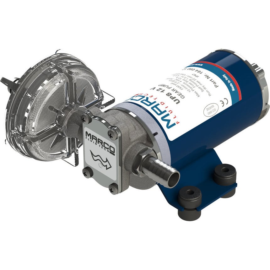
Gear pumps operate by compressing fluid between the inside wall of the gear housing and the trapped air volume of the meshing gear teeth. They are usually classified as internal or external, with internal gear pumps being the more reliable of the two. In addition, internal gear pumps can dry run for short periods. Most gear pumps need a fluid that can handle a maximum temperature and pressure of 158°F, 500 psi. Gear pumps work best with fluids that have an ISO VG viscosity of 15 to 32 for a max temperature of 140°F and 32 to 68 for a max temperature of 158°F.
In a vane pump, rotors with slots are mounted to a shaft that spins eccentrically to a cam ring, thus creating vane chambers. The vane chambers on the discharge side decrease in volume and force fluid out; those on the intake side increase in volume and draw fluid in. For vane pumps with an operating pressure of 500 psi, the ISO VG viscosity can range from 15 to 22. When the maximum operating pressure is around 1000 psi, the viscosity is heavily dependent on the maximum operating temperature. For operating temperatures up to 104°F, the viscosity should be between 10 and 15; for temperatures between 104 and 140°F, the recommended viscosity is 15 to 32. When maximum operating temperatures are expected to reach 158°F, a higher viscosity fluid on the order of 22 to 46 is highly recommended.
Piston pumps are a bit more complex and can achieve much higher levels of pressure than either vane or gear pumps. For low pressures around 500 psi and temperatures up to 158°F, the viscosity should be around 15 to 22. For medium to high pressures (around 4,250 psi), the viscosity is highly dependent on temperature as was the case with vane motors.
Unless a gear pump is being used in a very flammable environment, either petroleum-based or synthetic fluids should work well. The viscosity of fluid — which is one of the most important factors involved with selecting a hydraulic fluid — is heavily dependent on both temperature and pressure, with low-temperature working conditions requiring a lower-viscosity fluid. In addition, the fluid needs to be chemically compatible with the seals used in the pump; this is typically a problem related to the use of synthetic fluids.
MAC Hydraulics offers customized maintenance plans to meet your preventative maintenance needs and goals, and this includes helping you make sure that the most appropriate hydraulic fluid is being used in your systems. We also offer 24-hour emergency repair services and our service trucks are outfitted with the equipment needed to diagnose, troubleshoot, and repair your hydraulic systems.
All John Blue Centrifugal Pumps can run dry without damaging the seal. This, combined with a two-year factory-backed UNCONDITIONAL WARRANTY on cast-iron models, makes the John Blue Centrifugal Pumps second to no other pump manufacturer on the market today — all at an affordable price. Our centrifugal pumps are available with gas, electric, or hydraulic power sources.


 8613371530291