
running hydraulic pump dry brands
There are typically three types of hydraulic pump constructions found in mobile hydraulic applications. These include gear, piston, and vane; however, there are also clutch pumps, dump pumps, and pumps for refuse vehicles such as dry valve pumps and Muncie Power Products’ Live PakTM.
The hydraulic pump is the component of the hydraulic system that takes mechanical energy and converts it into fluid energy in the form of oil flow. This mechanical energy is taken from what is called the prime mover (a turning force) such as the power take-off or directly from the truck engine.
With each hydraulic pump, the pump will be of either a uni-rotational or bi-rotational design. As its name implies, a uni-rotational pump is designed to operate in one direction of shaft rotation. On the other hand, a bi-rotational pump has the ability to operate in either direction.
For truck-mounted hydraulic systems, the most common design in use is the gear pump. This design is characterized as having fewer moving parts, being easy to service, more tolerant of contamination than other designs and relatively inexpensive. Gear pumps are fixed displacement, also called positive displacement, pumps. This means the same volume of flow is produced with each rotation of the pump’s shaft. Gear pumps are rated in terms of the pump’s maximum pressure rating, cubic inch displacement and maximum input speed limitation.
Generally, gear pumps are used in open center hydraulic systems. Gear pumps trap oil in the areas between the teeth of the pump’s two gears and the body of the pump, transport it around the circumference of the gear cavity and then force it through the outlet port as the gears mesh. Behind the brass alloy thrust plates, or wear plates, a small amount of pressurized oil pushes the plates tightly against the gear ends to improve pump efficiency.
A cylinder block containing pistons that move in and out is housed within a piston pump. It’s the movement of these pistons that draw oil from the supply port and then force it through the outlet. The angle of the swash plate, which the slipper end of the piston rides against, determines the length of the piston’s stroke. While the swash plate remains stationary, the cylinder block, encompassing the pistons, rotates with the pump’s input shaft. The pump displacement is then determined by the total volume of the pump’s cylinders. Fixed and variable displacement designs are both available.
With a fixed displacement piston pump, the swash plate is nonadjustable. Its proportional output flow to input shaft speed is like that of a gear pump and like a gear pump, the fixed displacement piston pump is used within open center hydraulic systems.
As previously mentioned, piston pumps are also used within applications like snow and ice control where it may be desirable to vary system flow without varying engine speed. This is where the variable displacement piston pump comes into play – when the hydraulic flow requirements will vary based on operating conditions. Unlike the fixed displacement design, the swash plate is not fixed and its angle can be adjusted by a pressure signal from the directional valve via a compensator.
Vane pumps were, at one time, commonly used on utility vehicles such as aerial buckets and ladders. Today, the vane pump is not commonly found on these mobile (truck-mounted) hydraulic systems as gear pumps are more widely accepted and available.
Within a vane pump, as the input shaft rotates it causes oil to be picked up between the vanes of the pump which is then transported to the pump’s outlet side. This is similar to how gear pumps work, but there is one set of vanes – versus a pair of gears – on a rotating cartridge in the pump housing. As the area between the vanes decreases on the outlet side and increases on the inlet side of the pump, oil is drawn in through the supply port and expelled through the outlet as the vane cartridge rotates due to the change in area.
Input shaft rotates, causing oil to be picked up between the vanes of the pump which is then transported to pump outlet side as area between vanes decreases on outlet side and increases on inlet side to draw oil through supply port and expel though outlet as vane cartridge rotates
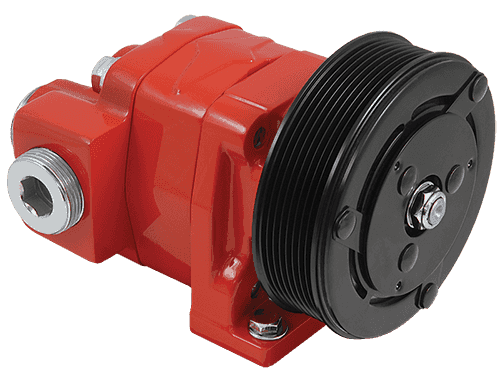
A clutch pump is a small displacement gear pump equipped with a belt-driven, electromagnetic clutch, much like that found on a car’s air conditioner compressor. It is engaged when the operator turns on a switch inside the truck cab. Clutch pumps are frequently used where a transmission power take-off aperture is not provided or is not easily accessible. Common applications include aerial bucket trucks, wreckers and hay spikes. As a general rule clutch pumps cannot be used where pump output flows are in excess of 15 GPM as the engine drive belt is subject to slipping under higher loads.
What separates this pump from the traditional gear pump is its built-in pressure relief assembly and an integral three-position, three-way directional control valve. The dump pump is unsuited for continuous-duty applications because of its narrow, internal paths and the subsequent likelihood of excessive heat generation.
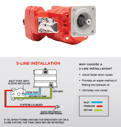
Dump pumps are often direct mounted to the power take-off; however, it is vital that the direct-coupled pumps be rigidly supported with an installer-supplied bracket to the transmission case with the pump’s weight at 70 lbs. With a dump pump, either a two- or three-line installation must be selected (two-line and three-line refer to the number of hoses used to plumb the pump); however, a dump pump can easily be converted from a two- to three-line installation. This is accomplished by inserting an inexpensive sleeve into the pump’s inlet port and uncapping the return port.
Many dump bodies can function adequately with a two-line installation if not left operating too long in neutral. When left operating in neutral for too long however, the most common dump pump failure occurs due to high temperatures. To prevent this failure, a three-line installation can be selected – which also provides additional benefits.
Pumps for refuse equipment include both dry valve and Live Pak pumps. Both conserve fuel while in the OFF mode, but have the ability to provide full flow when work is required. While both have designs based on that of standard gear pumps, the dry valve and Like Pak pumps incorporate additional, special valving.
Primarily used on refuse equipment, dry valve pumps are large displacement, front crankshaft-driven pumps. The dry valve pump encompasses a plunger-type valve in the pump inlet port. This special plunger-type valve restricts flow in the OFF mode and allows full flow in the ON mode. As a result, the horsepower draw is lowered, which saves fuel when the hydraulic system is not in use.
In the closed position, the dry valve allows just enough oil to pass through to maintain lubrication of the pump. This oil is then returned to the reservoir through a bleed valve and small return line. A bleed valve that is fully functioning is critical to the life of this type of pump, as pump failure induced by cavitation will result if the bleed valve becomes clogged by contaminates. Muncie Power Products also offer a butterfly-style dry valve, which eliminates the bleed valve requirement and allows for improved system efficiency.
It’s important to note that with the dry valve, wear plates and shaft seals differ from standard gear pumps. Trying to fit a standard gear pump to a dry valve likely will result in premature pump failure.
Encompasses plunger-type valve in the pump inlet port restricting flow in OFF mode, but allows full flow in ON mode lowering horsepower draw to save fuel when not in use
Wear plates and shaft seals differ from standard gear pumps – trying to fit standard gear pump to dry valve likely will result in premature pump failure
Live Pak pumps are also primarily used on refuse equipment and are engine crankshaft driven; however, the inlet on a Live Pak pump is not outfitted with a shut-off valve. With a Live Pak pump, the outlet incorporates a flow limiting valve. This is called a Live Pak valve. The valve acts as an unloading valve in OFF mode and a flow limiting valve in the ON mode. As a result, the hydraulic system speed is limited to keep within safe operating parameters.
Outlet incorporates flow limiting valve called Live Pak valve – acts as an unloading valve in OFF mode and flow limiting valve in ON mode restricting hydraulic system speed to keep within safe operating parameters
Did you know you can invalidate the warranty of your final drive motor if you make the mistake of dry starting it after you’ve just installed it? Read on to learn what a dry start it, how it can damage your motor, and how to keep it from happening to you.
Many people mistakenly believe that because hydraulic fluid circulates through the hydraulic system that all you need to do is connect the hoses to the right ports and you’re good to go. Just because the hydraulic fluid circulates doesn’t mean you can attach an empty component and expect it to be ready to run. And frankly, there is no excuse for dry starting the planetary side of a final drive motor because there is no circulation of fluid to fall back on.
That damage can lead to flakes and other tiny bits of metal breaking free and contaminating the hydraulic fluid or oil once it has access to these parts. Then you have
Scratches and abrasions lead to a reduction in performance, which means that a brand new final drive motor ends up with compromised efficiency and power from the start. In short, you’ve damaged the motor immediately after installation, and dry start damage is not covered by warranties.
Before starting a hydraulic motor that is either brand new, repaired, or rebuilt, add clean, new hydraulic fluid to the hydraulic hub and make sure there is fresh gear oil in the planetary hub. That is all you need to do in order to avoid a dry start.
Just a few simple steps can help you avoid damaging your final drive hydraulic motor by dry starting it. Since damage caused by a dry start is not covered by warranty, it is all the more important that you make sure your motor has fluid and gear oil before you start it.
is your partner in providing new or remanufactured final drive hydraulic motors from a single mini-excavator to a fleet of heavy equipment. Call today so we can find the right final drive or hydraulic component for you, or check out our online store to.
Pumps may become inefficient or even catastrophically fail simply because the wrong type of hydraulic fluid is used. How do you know if you are using the right kind of fluid for your hydraulic pump? The answer to that question is dependent on several factors, including the type of pump, its maximum operating temperature, its maximum operating pressure, and even the type of material the pump’s seals are made from.
Hydraulic fluid (sometimes referred to as hydraulic oil) can serve multiple purposes in a hydraulic system and its individual components — including pumps. These purposes include the following:
In the majority of cases, the most important factor is the ability of the fluid to transmit energy, but that can be compromised if too much heat is trapped within the pump, internal components are allowed to corrode, or there is not enough lubrication to prevent surface damage of the internal components.
The hydraulic pump is the heart of any hydraulic system, and the wrong choice of fluid can seriously impact the pump’s performance and life expectancy. In fact, the use of a fluid that is poorly matched to the pump can lead to a catastrophic failure that can cause cascading issues throughout the system. Issues that can arise as a result of poor fluid choice include:
When it comes time to select a fluid for your system, it is important to know what properties are important for your particular application. The most important characteristics of a hydraulic fluid include its viscosity, lubrication, thermal properties, flammability, stability, and foaming.
Viscosity is a measure of a fluid’s resistance to flow, with honey being an example of high viscosity, water being an example of medium-level viscosity, and most gases exhibiting very low viscosity. It is closely related to temperature, with hydraulic fluids becoming more viscous as temperatures drop.
If a hydraulic fluid has a viscosity that is too high, the system will not perform efficiently due to the losses involved in overcoming the resistance of the fluid to motion. In addition, damage can occur because components within the system will not be fully lubricated. However, if the viscosity is too low, there can still be lubrication issues and the fluid will not be as effective at transmitting energy.
A good hydraulic fluid will serve as a lubricant within the system, protecting critical surfaces from damage and preventing metal-to-metal contact. In some instances, a hydraulic system or pump may require a hydraulic fluid with additives to maintain its lubricity in the presence of high pressures.
For use in an explosive or highly flammable environment, hydraulic fluid should have a high flashpoint. The flashpoint is the temperature at which the hydraulic fluid gives off enough vapor to ignite in air. However, keep in mind that hydraulic fluids can also easily ignite if they are discharged under a high enough pressure to produce a fine oil mist. Hydraulic fluids should have a non-petroleum makeup or contain large amounts of water if flammability is an issue.
Ideally, a hydraulic fluid should be non-volatile. It should remain both physically and chemically stable even in the presence of extreme pressure fluctuations, a wide operating temperature range, and even long-term storage.
Another potential issue with hydraulic fluids is foaming, which occurs when the hydraulic fluid releases trapped gases. Foaming can result in an increased system temperature as well as a loss of hydraulic fluid as the gases are released.
There are three basic types of hydraulic fluid: water-based, petroleum-based, and synthetic. Each type has its own special characteristics that make it ideal for certain applications. In addition, there are some fluids that are preferred for applications that can affect the environment.
The oldest type of hydraulic fluid is water-based, but in modern times it is not used as much as other types of hydraulic fluid. Keep in mind that while water may not be as effective at lubrication, it is ideal for situations where the possibility of fire is a major concern. As far as the price goes, water-based fluids are cheaper than synthetic fluids but still more expensive than petroleum-based fluids.
The higher base oil groups help extend the life of your hydraulic pump by offering better corrosion resistance, stability, and lubrication. While they may not offer the same performance level as higher-cost synthetic fluids, the inclusion of additives will enhance their properties. One of the issues with petroleum-based hydraulic fluid, however, is the tendency to build up sludge, which can compromise the performance and efficiency of the hydraulic pump.
Additives comprise about 1% or less of petroleum-based fluids but have a tremendous impact on hydraulic fluid performance. Key additive package components include antioxidants, anti-wear components, foam inhibitors, viscosity modifiers, and rust inhibitors.
Synthetic hydraulic fluids are man-made and designed specifically for providing high-performance properties which also work well in flammable environments. These fluids are the most expensive, but they work better than the other types of hydraulic fluid when exposed to extreme temperature variations and high pressures. However, unlike petroleum-based and water-based fluids, they may be incompatible with certain seal materials and can be toxic.
Gear pumps operate by compressing fluid between the inside wall of the gear housing and the trapped air volume of the meshing gear teeth. They are usually classified as internal or external, with internal gear pumps being the more reliable of the two. In addition, internal gear pumps can dry run for short periods. Most gear pumps need a fluid that can handle a maximum temperature and pressure of 158°F, 500 psi. Gear pumps work best with fluids that have an ISO VG viscosity of 15 to 32 for a max temperature of 140°F and 32 to 68 for a max temperature of 158°F.
In a vane pump, rotors with slots are mounted to a shaft that spins eccentrically to a cam ring, thus creating vane chambers. The vane chambers on the discharge side decrease in volume and force fluid out; those on the intake side increase in volume and draw fluid in. For vane pumps with an operating pressure of 500 psi, the ISO VG viscosity can range from 15 to 22. When the maximum operating pressure is around 1000 psi, the viscosity is heavily dependent on the maximum operating temperature. For operating temperatures up to 104°F, the viscosity should be between 10 and 15; for temperatures between 104 and 140°F, the recommended viscosity is 15 to 32. When maximum operating temperatures are expected to reach 158°F, a higher viscosity fluid on the order of 22 to 46 is highly recommended.
Piston pumps are a bit more complex and can achieve much higher levels of pressure than either vane or gear pumps. For low pressures around 500 psi and temperatures up to 158°F, the viscosity should be around 15 to 22. For medium to high pressures (around 4,250 psi), the viscosity is highly dependent on temperature as was the case with vane motors.
Unless a gear pump is being used in a very flammable environment, either petroleum-based or synthetic fluids should work well. The viscosity of fluid — which is one of the most important factors involved with selecting a hydraulic fluid — is heavily dependent on both temperature and pressure, with low-temperature working conditions requiring a lower-viscosity fluid. In addition, the fluid needs to be chemically compatible with the seals used in the pump; this is typically a problem related to the use of synthetic fluids.
MAC Hydraulics offers customized maintenance plans to meet your preventative maintenance needs and goals, and this includes helping you make sure that the most appropriate hydraulic fluid is being used in your systems. We also offer 24-hour emergency repair services and our service trucks are outfitted with the equipment needed to diagnose, troubleshoot, and repair your hydraulic systems.

The goal of a hydraulic pump is to move hydraulic fluid through a hydraulic system, acting much like the beating heart of the system. There are two things that all hydraulic pumps have in common: (1) they provide hydraulic flow to other components (e.g., rams, hydraulic motors, cylinder) within a hydraulic system, and (2) they produce flow which in turn generates pressure when there is a resistance to flow. In addition, most hydraulic pumps are motor-driven and include a pressure relief valve as a type of overpressure protection. The three most common types of hydraulic pumps currently in use are gear, piston, and vane pumps.
In a gear pump, hydraulic fluid is trapped between the body of the pump and the areas between the teeth of the pump’s two meshing gears. The driveshaft is used to power one gear while the other remains idle until it meshes with the driving gear. These pumps are what is known as fixed displacement or positive displacement because each rotation of the shaft displaces the same amount of hydraulic fluid at the same pressure. There are two basic types of gear pumps, external and internal, which will be discussed in a moment.
Gear pumps are compact, making them ideal for applications that involve limited space. They are also simple in design, making them easier to repair and maintain. Note that gear pumps usually exhibit the highest efficiency when running at their maximum speed. In general, external gear pumps can produce higher levels of pressure (up to 3,000 psi) and greater throughput than vane pumps.
External gear pumps are often found in close-coupled designs where the gear pump and the hydraulic motor share the same mounting and the same shaft. In an external gear pump, fluid flow occurs around the outside of a pair of meshed external spur gears. The hydraulic fluid moves between the housing of the pump and the gears to create the alternating suction and discharge needed for fluid flow.
External gear pumps can provide very high pressures (up to 3,000 psi), operate at high speeds (3,000 rpm), and run more quietly than internal gear pumps. When gear pumps are designed to handle even higher pressures and speeds, however, they will be very noisy and there may be special precautions that must be made.
External gear pumps are often used in powerlifting applications, as well as areas where electrical equipment would be either too bulky, inconvenient, or costly. External gear pumps can also be found on some agricultural and construction equipment to power their hydraulic systems.
In an internal gear pump, the meshing action of external and internal gears works with a crescent-shaped sector element to generate fluid flow. The outer gear has teeth pointing inwards and the inner gear has teeth pointing outward. As these gears rotate and come in and out of mesh, they create suction and discharge zones with the sector acting as a barrier between these zones. A gerotor is a special type of internal gear pump that eliminates the need for a sector element by using trochoidal gears to create suction and discharge zones.
Unlike external gear pumps, internal gear pumps are not meant for high-pressure applications; however, they do generate flow with very little pulsation present. They are not as widely used in hydraulics as external gear pumps; however, they are used with lube oils and fuel oils and work well for metering applications.
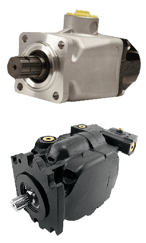
In a piston pump, reciprocating pistons are used to alternately generate suction and discharge. There are two different ways to categorize piston pumps: whether their piston is axially or radially mounted and whether their displacement is fixed or variable.
Piston pumps can handle higher pressures than gear or vane pumps even with comparable displacements, but they tend to be more expensive in terms of the initial cost. They are also more sensitive to contamination, but following strict hydraulic cleanliness guidelines and filtering any hydraulic fluid added to the system can address most contamination issues.
In an axial piston pump, sometimes called an inline axial pump, the pistons are aligned with the axis of the pump and arranged within a circular cylinder block. On one side of the cylinder block are the inlet and outlet ports, while an angled swashplate lies on the other side. As the cylinder block rotates, the pistons move in and out of the cylinder block, thus creating alternating suction and discharge of hydraulic fluid.
Axial piston pumps are ideal for high-pressure, high-volume applications and can often be found powering mission-critical hydraulic systems such as those of jet aircraft.
In a bent-axis piston pump (which many consider a subtype of the axial piston pump), the pump is made up of two sides that meet at an angle. On one side, the drive shaft turns the cylinder block that contains the pistons which match up to bores on the other side of the pump. As the cylinder block rotates, the distances between the pistons and the valving surface vary, thus achieving the necessary suction and discharge.
In a radial piston pump, the pistons lie perpendicular to the axis of the pump and are arranged radially like spokes on a wheel around an eccentrically placed cam. When the drive shaft rotates, the cam moves and pushes the spring-loaded pistons inward as it passes them. Each of these pistons has its own inlet and outlet ports that lead to a chamber. Within this chamber are valves that control the release and intake of hydraulic fluid.
In a fixed displacement pump, the amount of fluid discharged in each reciprocation is the same volume. However, in a variable displacement pump, a change to the angle of the adjustable swashplate can increase or reduce the volume of fluid discharged. This design allows you to vary system speed without having to change engine speed.
When the input shaft of a vane pump rotates, rigid vanes mounted on an eccentric rotor pick up hydraulic fluid and transport it to the outlet of the pump. The area between the vanes increases on the inlet side as hydraulic fluid is drawn inside the pump and decreases on the outlet side to expel the hydraulic fluid through the output port. Vane pumps can be either fixed or variable displacement, as discussed for piston pumps.
Vane pumps are used in utility vehicles (such as those with aerial ladders or buckets) but are not as common today, having been replaced by gear pumps. This does not mean, however, that they are not still in use. They are not designed to handle high pressures but they can generate a good vacuum and even run dry for short periods of time.
There are other key aspects to choosing the right hydraulic pump that goes beyond deciding what type is best adapted to your application. These pump characteristics include the following:
Selecting a pump can be very challenging, but a good place to start is looking at the type of pump that you need. Vane pumps have been largely replaced by compact, durable gear pumps, with external gear pumps working best for high pressure and operating speeds while internal gear pumps are able to generate flow with very little pulsation. However, vane pumps are still good for creating an effective vacuum and can run even when dry for short periods of time. Piston pumps in general are more powerful but, at the same time, more susceptible to contamination.
Whether the pump is needed for the rugged world of mining, the sterile world of food and beverage processing, or the mission-critical aerospace industry, MAC Hydraulics can assist you with selecting, installing, maintaining, and repairing the right pump to meet the needs of your hydraulic system. In the event of a breakdown, our highly skilled technicians can troubleshoot and repair your pump — no matter who the manufacturer happens to be. We also offer on-site services that include common repairs, preventative maintenance, lubrication, cleaning, pressure testing, and setting.
The TP03 and TP08 lines of trash pumps are a great example of the power of hydraulics when it comes to pumping liquids with solids. The TP03 pump provides 450 gallons per minute (1688 lpm) of discharge capacity and can pump solids up to 3 inch (76 mm) in diameter. The TP08 has a 800 gpm (3028 lpm) of discharge capacityand can pump up to 4 inch (102 mm) diameter solids.

The SM50 water pump is fitted with dripless flat-faced HTMA quick couplers for easy connecting and disconnecting of the pump and hydraulic system. The water outlet is a 3-inch pipe thread fitted with a 3-inch groove fitting to which can be connected a cam hose end fitting. Access to the pumping chamber for cleaning requires the removal of only two cap screws. The motor with the impeller attached is then easily removed from the pump casing. The SM50 can draw down water to a depth of 3.5 inches. Putting the SM50 in a sump will allow it to pump all but 3.5 inches of water remaining in the sump. The integral screen effectively keeps solids larger than 3/8 of an inch out of the pump. The pump will handle clear water and water containing up to 10% solids.

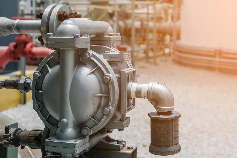
Dry Running is an undesirable condition which affects most pump designs and is characterised when a pump operates without an adequate amount of fluid. In most pump technologies, this leads to cavitation and critical damage to the internal pumping elements such as impellers, lobes, gears, casings, seals & bearings.
Dry running is usually related to how the pump is operated, monitored & controlled which is typically a result of human error. Companies generally rely on their operators to monitor the pumps on the line, however, problems will arise when a pump is unintentionally left running for prolonged periods of time after the intended operation has been completed. For example, during offloading of a tanker, an operator may leave the pump unattended whilst the tanker is being evacuated and the pump may over-run when the tanker is empty thus resulting in damage to the pump internals.
Dry running could lead mechanical seals to wearing quickly which could cause the pump to leak. This will allow the potentially hazardous liquid to spill putting pump operators at risk.
Dry running can damage your pump which could cause an immediate stop to your production line meaning a loss of production – delays & costs to your business
Risked cavitation if dry run for long periods of time which may require the whole pump to be replaced if there has been serious damage to the impellers in your pump
Dry Running can be extremely costly to your business so please check with your supplier or the pump manufacturer whether the pump you’ve purchased can be dry run before operating it.
When using most pump designs, such as Rotodynamic as well as Reciprocating and Rotary Positive Displacement Pumps, most companies need to install protection and control devises on the pumps and system to ensure that the pump is stopped immediately after the pumping operation is complete, or in the absence of fluid at the pump suction or source.
Pressure or Level Switch Protection:Pressure Switches fitted to the suction pipe or port of the pump(s) or Float Switches/Electrode Relays in the Supply tank
Engineers on-site and Operators spend significant amounts of time ensuring pumps are properly installed & primed, significantly increasing the cost and complexity of the installation. However, despite all these efforts, the ever-present possibility of human error, malfunctioning control and monitoring equipment, unpredictable events & improper use of equipment means that Dry Running is never completely eradicated. As a result, plant owners are constantly in search of technology and solutions which can prevent or avoid the costly and damaging effects of Dry Running in order to reduce maintenance costs, increase throughput and alleviate pressures put onto operators to constantly monitor, control and protect their equipment on the line.
There are a variety of standard accessories that can be used to control pumping equipment to protect is from dry running such as pressure and temperature sensors. Additional accessories and expensive sealing systems aren’t always the answer. Not all pumps are created equally, in fact, at Tapflo UK we have a variety of pump solutions that will allow you to dry run your pump without causing damage to it. Need your pump to run dry? Let us know when you call us.
Tapflo offer a range of pump technologies that have the added benefit of being able to dry run, including our Diaphragm Pumps and Peristaltic Pumps which can run dry indefinitely without damaging the pump.
Due to their design and construction, both of these pumping technologies are able to operate under dry conditions without experiencing common wear problems associated with dry running. Not only does this alleviate the pressure put on the operator, but it also simplifies the pumping system and reduces the cost of installation and ownership significantly. Of course, these designs, on their own, do not overcome the energy costs affiliated with overrunning equipment, to improve this, Tapflo offers dry run protection devices such as our Pneumatic Guardian System for Diaphragm Pumps which automatically stops your pump when the pumping process is complete.
In summary, Tapflo UK have a full range of pumping solutions which can either protect equipment from Dry Running or indeed avoid problems associated with Dry Running completely! Let’s discuss your options today.

Repairing and supplying remanufactured and new Hydreco Hydraulics – Hydreco Hydraulics pumps, Hydreco Hydraulics valves, Hydreco Hydraulics cylinders and Hydreco Hydraulics motors. Search our online catalog or contact us and let us know how we can help you.
We can supply what you need or repair what you have. There may be a good chance before purchasing that your current Hydreco hydraulic pump, or motor can be repaired. Hydreco Hydraulics pump and motor repairs come with our two year warranty, giving you peace of mind with any Hydreco hydraulic pump purchase.
When purchasing, consider Hydreco Hydraulics remanufactured or after-market hydraulic units. Best of all they can get you back up and running for less than the cost of a new hydraulic unit. We will give you a free quote so you can compare costs for a new, repaired or remanufactured Hydreco Hydraulics unit, saving you time and money with the best return on investment for your situation.
Hydreco Hydraulics has 100 years in developing solutions which includes their offer designing, manufacturing and distributing products servicing the transport and mobile hydraulics sector. David Brown Hydraulics joined Powauto and Hydreco in 1997. Under the name Hydreco Powauto, Hydreco Hydraulics sells a variety of transport hydraulic products which cover power take-off units, pumps, valves, cylinders and accessories for on and off road vehicles.
Engineering is at the core of Hydreco Hydraulics, thus offering product solutions for applications within construction, earth moving, transport, industrial and materials handling. Products evolved and advanced, leading to a series of some of the highest quality products available.
Hydreco Hydraulics’ extensive range includes low noise helical gear, aluminum and cast iron gear pumps and standard spur gear models from David Brown. Valves include multi-spool sectional and mono-block models with electro hydraulic and lever control which come with spring focused and electric detent options.Appliances include dual axis, stackable and single axis hydraulic pilot valves. These include a wide range of handle options including ergonomic handles with many switches and button options.
Hydreco Gear PumpsHelical gear and spur gear pumps together have cast iron and aluminum bodies, offer stability, long life and high efficiency combined with low noise. These Hydreco hydraulic pump models include:
Powauto Gear Pumps & Piston PumpsSelect from 13 gear pump sizes, ranging from 25cc to 115cc in addition to 10 sizes of bent axis piston pumps generate up to 350 bars and include popular ports and mountings.
Gear Pumps: PUT20 UNI Series pumps come in 7 displacements from 6.1 to 40.2 ccm/rev. while pump range has superseded the CF range in five pump sizes for general and high pressure use.
Hydreco Dump Pumps & Dry Valve PumpsLow cost and low maintenance dump pumps premium bearings offer a long life and durability. Dry Valves have a smaller overall length with 3000 psi rated pressure. They have higher pressure in select models while horsepower demand is reduced when hydraulic power is not required. This makes these Hydreco Hydraulic pumps a viable choice for varied pressure needs.
Powauto Hydraulic Transport ValvesControl options include manual, pilot hydraulic, pneumatic and electro hydraulic. Depending on the model, features include sectional or mono-block construction, flow rating to 450 liters/min, tandem circuits, and many inlets. Additional features include hard chrome spools for longer life, large ports/spool passages for maximum flow with minimum pressure drop, and simple design for trouble free operation and installation.
Welcome to the Ag Superstore guide to Hypro Pumps Centrifugal pumps. In this guide, we will be looking at what makes the centrifugal pump the most popular pump in the Agriculture industry. Along with this, we’ll point out the key things you need to know, along with some tips on how to maintain your centrifugal pump
Centrifugal pumps aredesigned to move fluid by means of the transfer of rotational energy from one or more driven rotors, called impellers.The impeller typically is driven by a hydraulic or electric or motor. The speed of the motor or in the case of the Hydraulic motor is governed by the oil flow available determines the speed of the impeller and hence the flow and the pressure out of the pump.
Centrifugal pumps rely on constant, high speed rotation of the impellers. If the pumping fluid is of a high viscosity centrifugal pumps become increasingly inefficient as there is greater resistance and higher pressure is needed to maintain the flow rate. In general, centrifugal pumps are therefore suited to low pressure, high capacity, pumping applications of liquids with viscosities between 0.1 and 200 cP.
High Viscosity fluids such as mud and oils can cause excessive wear and overheating leading to damage or even premature failure.Diaphragm pumpsoften operate at considerably lower speeds and are less prone to these problems.
Most of thepumps that are used in Agriculture and farming are centrifugal pumps as they offer a simple and relatively low-cost solution to low pressure and high-capacity pumping situations.
Centrifugal pumps are typically the go-to choice for transferring lower viscosity fluids. Since less viscous liquids are much easier to accelerate with kinetic energy, centrifugal pumps can transfer them much more efficiently than other designs. This is what makes them perfect for boom spraying applications as you’re going to be pumping a low viscosity liquid in a consistent and even manner.
Keeping your Centrifugal pump running is easy so long as you follow some rules. Ignoring these rules will result in increased downtime and increased cost to repair.
The mechanical seal enables the fluid from the hydraulic motor to power the impeller without the oil from the motor contaminating the fluid you’re pumping. It’s important that this seal remains lubricated from the product you are pumping.
Cavitation is a problem for all pumps however it is specifically an issue for centrifugal pumps. The eye is the inlet area of the pump where the fluid impacts the spinning impeller. When the pressure is too low, bubbles form. As the product spins faster through the impeller the pressure increases and the bubbles collapse and turns to vapour.
Hypro is a brand with over 50 years of experience in developing centrifugal pumps and motors for fluid transfer. We recommendHypro Pumpsas a cheap and effective sprayer pump solution for all of your low viscosity spraying needs. Hypro pumps specifically develop centrifugal pumps, and whilst they are a cheaper alternative to a diaphragm pump we hope you can apply all the information you’ve learnt in the above blog to keep your Hypro Pump running for years to come.
If you have any questions about our pumps or anything Ag don’t hesitate to give the team at Ag Superstore a call.Check out our range of Hypro Agriculture and Spraying Pumps.

Facility operators in the oil and gas industry have raised concerns on how to solve their top failure modes: extremely short or non-existent dry run pump time limits and unacceptable levels of cavitation when pumping extremely light liquids with high vapor pressures.
Pump cavitation and dry run related failures cost companies millions of dollars annually, including replacement costs for damaged equipment and lost sales due to poor performance. With an improving economy and anticipated fuel production increase, sales of fluid-handling pumps are forecast to rise 5.5% annually to $84 billion in 2018. Given this proliferation, the historical pattern suggests that costs associated with repairs or replacements also will increase dramatically.
Learn how Parker"s innovation in pump technology can reduce your operational downtime, decrease operating costs, and improve performance. Download our white paper now.
Dry running occurs when a pump operates without sufficient lubricating liquid around the pumping element. This can be caused by either widespread vapor formation, also known as cavitation, inside the pump or absence of pumping fluid altogether. These adverse conditions can lead to dangerously unstable pressure, flow, or overheating which may cause the pumping element to seize or break.
When cavitation occurs, vapor bubbles form and expand in the pumping liquid on the suction side of the pump before reaching the higher-pressure discharge side of the pump and violently collapsing near the surface of the pumping element. This triggers shock waves inside the pump which cause significant damage to the pumping element. If left untreated, cavitation will destroy the pumping element and other components over time, drastically shortening the pump’s life.
Cavitation itself may also be so widespread that it creates a dry run situation inside the pump due to excessive vapor formation. Pumps most often rely on the pumping fluid itself to lubricate the bearing surfaces of the pumping element – if a pump is operated without this fluid, the low to non-existent lubrication at these bearing surfaces will cause excess heat generation, increased wear, and potentially even failure of the pump if the pumping element seizes or breaks. The life of a pump subjected to dry run will be significantly reduced or, in the worst case, brought to an untimely end.
“What separates our solution from our competitors is, our technology is automated and integrated into the pump design. You don’t need to worry about pumps stopping and starting every 20 – 30 seconds, they will dry run continuously.”
Learn how this innovation in pump technology can reduce your operational downtime, decrease operating costs, and improve performance. Download our white paper now.
While the sliding vane pump and internal/external gear pump operating principles have set the standard in reliable, efficient, and safe positive displacement pump operation for centuries, sliding vane pumps will functionally outperform their gear pump cousins in a number of important ways. These include internal clearances, component lifespan, system functionality, relief valve cracking pressure, and liquid compatibility.
Gear pumps are compact and simple with a limited number of moving parts. They are unable to match the pressure generated by reciprocating pumps or the flow rates of centrifugal pumps but offer higher pressures and throughputs than vane or lobe pumps. Winston engineering is manufacturing and supplying high-quality gear pimps in Malaysia. Visit us herehttps://www.winstonengineering.com/my
Gear pumps are self-priming and can dry-lift although their priming characteristics improve if the gears are wetted. The gears need to be lubricated by the pumped fluid and should not be run dry for prolonged periods. Some gearpump designs can be run in either direction so the same pump can be used to load and unload a vessel.
The gear pump may be in style selection for several applications. They aren"t continually used for water, though. They are utilized in the organic compound and chemical industries and build nice pumps for hydraulic applications. They can be used for viscous and aggressive fluids.Choose Winston Engineering, the gear pump expert in Malaysia.
There are two types of gear pumps –external gear pumps and internal gear pumps. External gear pumps build use of 2 external opposing gears (typically spur gears) in transferring the fluid sort.

Check that the electric motor is running. Although this is a simple concept, before you begin replacing parts, it’s critical that you make sure the electric motor is running. This can often be one of the easiest aspects to overlook, but it is necessary to confirm before moving forward.
Check that the pump shaft is rotating. Even though coupling guards and C-face mounts can make this difficult to confirm, it is important to establish if your pump shaft is rotating. If it isn’t, this could be an indication of a more severe issue, and this should be investigated immediately.
Check the oil level. This one tends to be the more obvious check, as it is often one of the only factors inspected before the pump is changed. The oil level should be three inches above the pump suction. Otherwise, a vortex can form in the reservoir, allowing air into the pump.
What does the pump sound like when it is operating normally? Vane pumps generally are quieter than piston and gear pumps. If the pump has a high-pitched whining sound, it most likely is cavitating. If it has a knocking sound, like marbles rattling around, then aeration is the likely cause.
Cavitation is the formation and collapse of air cavities in the liquid. When the pump cannot get the total volume of oil it needs, cavitation occurs. Hydraulic oil contains approximately nine percent dissolved air. When the pump does not receive adequate oil volume at its suction port, high vacuum pressure occurs.
This dissolved air is pulled out of the oil on the suction side and then collapses or implodes on the pressure side. The implosions produce a very steady, high-pitched sound. As the air bubbles collapse, the inside of the pump is damaged.
While cavitation is a devastating development, with proper preventative maintenance practices and a quality monitoring system, early detection and deterrence remain attainable goals. UE System’s UltraTrak 850S CD pump cavitation sensor is a Smart Analog Sensor designed and optimized to detect cavitation on pumps earlier by measuring the ultrasound produced as cavitation starts to develop early-onset bubbles in the pump. By continuously monitoring the impact caused by cavitation, the system provides a simple, single value to trend and alert when cavitation is occurring.
The oil viscosity is too high. Low oil temperature increases the oil viscosity, making it harder for the oil to reach the pump. Most hydraulic systems should not be started with the oil any colder than 40°F and should not be put under load until the oil is at least 70°F.
Many reservoirs do not have heaters, particularly in the South. Even when heaters are available, they are often disconnected. While the damage may not be immediate, if a pump is continually started up when the oil is too cold, the pump will fail prematurely.
The suction filter or strainer is contaminated. A strainer is typically 74 or 149 microns in size and is used to keep “large” particles out of the pump. The strainer may be located inside or outside the reservoir. Strainers located inside the reservoir are out of sight and out of mind. Many times, maintenance personnel are not even aware that there is a strainer in the reservoir.
The suction strainer should be removed from the line or reservoir and cleaned a minimum of once a year. Years ago, a plant sought out help to troubleshoot a system that had already had five pumps changed within a single week. Upon closer inspection, it was discovered that the breather cap was missing, allowing dirty air to flow directly into the reservoir.
A check of the hydraulic schematic showed a strainer in the suction line inside the tank. When the strainer was removed, a shop rag was found wrapped around the screen mesh. Apparently, someone had used the rag to plug the breather cap opening, and it had then fallen into the tank. Contamination can come from a variety of different sources, so it pays to be vigilant and responsible with our practices and reliability measures.
The electric motor is driving the hydraulic pump at a speed that is higher than the pump’s rating. All pumps have a recommended maximum drive speed. If the speed is too high, a higher volume of oil will be needed at the suction port.
Due to the size of the suction port, adequate oil cannot fill the suction cavity in the pump, resulting in cavitation. Although this rarely happens, some pumps are rated at a maximum drive speed of 1,200 revolutions per minute (RPM), while others have a maximum speed of 3,600 RPM. The drive speed should be checked any time a pump is replaced with a different brand or model.
Every one of these devastating causes of cavitation threatens to cause major, irreversible damage to your equipment. Therefore, it’s not only critical to have proper, proactive practices in place, but also a monitoring system that can continuously protect your valuable assets, such as UE System’s UltraTrak 850S CD pump cavitation senor. These sensors regularly monitor the health of your pumps and alert you immediately if cavitation symptoms are present, allowing you to take corrective action before it’s too late.
Aeration is sometimes known as pseudo cavitation because air is entering the pump suction cavity. However, the causes of aeration are entirely different than that of cavitation. While cavitation pulls air out of the oil, aeration is the result of outside air entering the pump’s suction line.
Several factors can cause aeration, including an air leak in the suction line. This could be in the form of a loose connection, a cracked line, or an improper fitting seal. One method of finding the leak is to squirt oil around the suction line fittings. The fluid will be momentarily drawn into the suction line, and the knocking sound inside the pump will stop for a short period of time once the airflow path is found.
A bad shaft seal can also cause aeration if the system is supplied by one or more fixed displacement pumps. Oil that bypasses inside a fixed displacement pump is ported back to the suction port. If the shaft seal is worn or damaged, air can flow through the seal and into the pump’s suction cavity.
As mentioned previously, if the oil level is too low, oil can enter the suction line and flow into the pump. Therefore, always check the oil level with all cylinders in the retracted position.
If a new pump is installed and pressure will not build, the shaft may be rotating in the wrong direction. Some gear pumps can be rotated in either direction, but most have an arrow on the housing indicating the direction of rotation, as depicted in Figure 2.
Pump rotation should always be viewed from the shaft end. If the pump is rotated in the wrong direction, adequate fluid will not fill the suction port due to the pump’s internal design.
A fixed displacement pump delivers a constant volume of oil for a given shaft speed. A relief valve must be included downstream of the pump to limit the maximum pressure in the system.
After the visual and sound checks are made, the next step is to determine whether you have a volume or pressure problem. If the pressure will not build to the desired level, isolate the pump and relief valve from the system. This can be done by closing a valve, plugging the line downstream, or blocking the relief valve. If the pressure builds when this is done, there is a component downstream of the isolation point that is bypassing. If the pressure does not build up, the pump or relief valve is bad.
If the system is operating at a slower speed, a volume problem exists. Pumps wear over time, which results in less oil being delivered. While a flow meter can be installed in the pump’s outlet line, this is not always practical, as the proper fittings and adapters may not be available. To determine if the pump is badly worn and bypassing, first check the current to the electric motor. If possible, this test should be made when the pump is new to establish a reference. Electric motor horsepower is relative to the hydraulic horsepower required by the system.
For example, if a 50-GPM pump is used and the maximum pressure is 1,500 psi, a 50-hp motor will be required. If the pump is delivering less oil than when it was new, the current to drive the pump will drop. A 230-volt, 50-hp motor has an average full load rating of 130 amps. If the amperage is considerably lower, the pump is most likely bypassing and should be changed.
Figure 4.To isolate a fixed displacement pump and relief valve from the system, close a valve or plug the line downstream (left). If pressure builds, a component downstream of the isolation point is bypassing (right).
The most common type of variable displacement pump is the pressure-compensating design. The compensator setting limits the maximum pressure at the pump’s outlet port. The pump should be isolated as described for the fixed displacement pump.
If pressure does not build up, the relief valve or pump compensator may be bad. Prior to checking either component, perform the necessary lockout procedures and verify that the pressure at the outlet port is zero psi. The relief valve and compensator can then be taken apart and checked for contamination, wear, and broken springs.
Install a flow meter in the case drain line and check the flow rate. Most variable displacement pumps bypass one to three percent of the maximum pump volume through the case drain line. If the flow rate reaches 10 percent, the pump should be changed. Permanently installing a flow meter in the case drain line is an excellent reliability and troubleshooting tool.
Ensure the compensator is 200 psi above the maximum load pressure. If set too low, the compensator spool will shift and start reducing the pump volume when the system is calling for maximum volume.
Performing these recommended tests should help you make good decisions about the condition of your pumps or the cause of pump failures. If you change a pump, have a reason for changing it. Don’t just do it because you have a spare one in stock.
Conduct a reliability assessment on each of your hydraulic systems so when an issue occurs, you will have current pressure and temperature readings to consult.
Al Smiley is the president of GPM Hydraulic Consulting Inc., located in Monroe, Georgia. Since 1994, GPM has provided hydraulic training, consulting and reliability assessments to companies in t...

This new lineup of pumps will strengthen the complete line of fertilizer products SurePoint already offers. For over 10 years, the SurePoint PumpRight has been the building block for our higher rate fertilizer systems. SurePoint has sold thousands of the D-series pumps to apply liquid across the globe and feels confident in this new line up of Gen-2 pumps will continue to be a reliable component of our fertilizer systems.
The PumpRight will continue to be driven by an Eaton hydraulic 4.0 cubic inch motor. Mounted to the hydraulic motor is a custom variable rate PWM control block. SurePoint’s PWM driven hydraulic motor has a built in by-pass that allows the PumpRight to be used in series with other hydraulic components on the toolbar. There is also a “manual override” that allows us to run the pump with hydraulic oil only, cutting out the need for PWM signal. With less than 9 GPM of hydraulic oil, you can reach the max capacity of the hydraulic pump.
The PumpRight is a reliable pump solution that will last several seasons with proper care and maintenance. It has a tremendous amount of suction which allows us to pull product from several feet away. With over 15’ of vertical lift, pulling from long distances won’t be a problem anymore. All PumpRight hydraulic driven diaphragm pumps are an oil lubricated pump giving the pump the ability to run dry. These positive displacement pumps will deliver a smooth, consistent flow output throughout the entire range of the pump.


 8613371530291