
simple hydraulic pump diagram brands
Hydraulic pumps are mechanisms in hydraulic systems that move hydraulic fluid from point to point initiating the production of hydraulic power. Hydraulic pumps are sometimes incorrectly referred to as “hydrolic” pumps.
They are an important device overall in the hydraulics field, a special kind of power transmission which controls the energy which moving fluids transmit while under pressure and change into mechanical energy. Other kinds of pumps utilized to transmit hydraulic fluids could also be referred to as hydraulic pumps. There is a wide range of contexts in which hydraulic systems are applied, hence they are very important in many commercial, industrial, and consumer utilities.
“Power transmission” alludes to the complete procedure of technologically changing energy into a beneficial form for practical applications. Mechanical power, electrical power, and fluid power are the three major branches that make up the power transmission field. Fluid power covers the usage of moving gas and moving fluids for the transmission of power. Hydraulics are then considered as a sub category of fluid power that focuses on fluid use in opposition to gas use. The other fluid power field is known as pneumatics and it’s focused on the storage and release of energy with compressed gas.
"Pascal"s Law" applies to confined liquids. Thus, in order for liquids to act hydraulically, they must be contained within a system. A hydraulic power pack or hydraulic power unit is a confined mechanical system that utilizes liquid hydraulically. Despite the fact that specific operating systems vary, all hydraulic power units share the same basic components. A reservoir, valves, a piping/tubing system, a pump, and actuators are examples of these components. Similarly, despite their versatility and adaptability, these mechanisms work together in related operating processes at the heart of all hydraulic power packs.
The hydraulic reservoir"s function is to hold a volume of liquid, transfer heat from the system, permit solid pollutants to settle, and aid in releasing moisture and air from the liquid.
Mechanical energy is changed to hydraulic energy by the hydraulic pump. This is accomplished through the movement of liquid, which serves as the transmission medium. All hydraulic pumps operate on the same basic principle of dispensing fluid volume against a resistive load or pressure.
Hydraulic valves are utilized to start, stop, and direct liquid flow in a system. Hydraulic valves are made of spools or poppets and can be actuated hydraulically, pneumatically, manually, electrically, or mechanically.
The end result of Pascal"s law is hydraulic actuators. This is the point at which hydraulic energy is transformed back to mechanical energy. This can be accomplished by using a hydraulic cylinder to transform hydraulic energy into linear movement and work or a hydraulic motor to transform hydraulic energy into rotational motion and work. Hydraulic motors and hydraulic cylinders, like hydraulic pumps, have various subtypes, each meant for specific design use.
The essence of hydraulics can be found in a fundamental physical fact: fluids are incompressible. (As a result, fluids more closely resemble solids than compressible gasses) The incompressible essence of fluid allows it to transfer force and speed very efficiently. This fact is summed up by a variant of "Pascal"s Principle," which states that virtually all pressure enforced on any part of a fluid is transferred to every other part of the fluid. This scientific principle states, in other words, that pressure applied to a fluid transmits equally in all directions.
Furthermore, the force transferred through a fluid has the ability to multiply as it moves. In a slightly more abstract sense, because fluids are incompressible, pressurized fluids should keep a consistent pressure just as they move. Pressure is defined mathematically as a force acting per particular area unit (P = F/A). A simplified version of this equation shows that force is the product of area and pressure (F = P x A). Thus, by varying the size or area of various parts inside a hydraulic system, the force acting inside the pump can be adjusted accordingly (to either greater or lesser). The need for pressure to remain constant is what causes force and area to mirror each other (on the basis of either shrinking or growing). A hydraulic system with a piston five times larger than a second piston can demonstrate this force-area relationship. When a force (e.g., 50lbs) is exerted on the smaller piston, it is multiplied by five (e.g., 250 lbs) and transmitted to the larger piston via the hydraulic system.
Hydraulics is built on fluids’ chemical properties and the physical relationship between pressure, area, and force. Overall, hydraulic applications allow human operators to generate and exert immense mechanical force with little to no physical effort. Within hydraulic systems, both oil and water are used to transmit power. The use of oil, on the other hand, is far more common, owing in part to its extremely incompressible nature.
Pressure relief valves prevent excess pressure by regulating the actuators’ output and redirecting liquid back to the reservoir when necessary. Directional control valves are used to change the size and direction of hydraulic fluid flow.
While hydraulic power transmission is remarkably useful in a wide range of professional applications, relying solely on one type of power transmission is generally unwise. On the contrary, the most efficient strategy is to combine a wide range of power transmissions (pneumatic, hydraulic, mechanical, and electrical). As a result, hydraulic systems must be carefully embedded into an overall power transmission strategy for the specific commercial application. It is necessary to invest in locating trustworthy and skilled hydraulic manufacturers/suppliers who can aid in the development and implementation of an overall hydraulic strategy.
The intended use of a hydraulic pump must be considered when selecting a specific type. This is significant because some pumps may only perform one function, whereas others allow for greater flexibility.
The pump"s material composition must also be considered in the application context. The cylinders, pistons, and gears are frequently made of long-lasting materials like aluminum, stainless steel, or steel that can withstand the continuous wear of repeated pumping. The materials must be able to withstand not only the process but also the hydraulic fluids. Composite fluids frequently contain oils, polyalkylene glycols, esters, butanol, and corrosion inhibitors (though water is used in some instances). The operating temperature, flash point, and viscosity of these fluids differ.
In addition to material, manufacturers must compare hydraulic pump operating specifications to make sure that intended utilization does not exceed pump abilities. The many variables in hydraulic pump functionality include maximum operating pressure, continuous operating pressure, horsepower, operating speed, power source, pump weight, and maximum fluid flow. Standard measurements like length, rod extension, and diameter should be compared as well. Because hydraulic pumps are used in lifts, cranes, motors, and other heavy machinery, they must meet strict operating specifications.
It is critical to recall that the overall power generated by any hydraulic drive system is influenced by various inefficiencies that must be considered in order to get the most out of the system. The presence of air bubbles within a hydraulic drive, for example, is known for changing the direction of the energy flow inside the system (since energy is wasted on the way to the actuators on bubble compression). Using a hydraulic drive system requires identifying shortfalls and selecting the best parts to mitigate their effects. A hydraulic pump is the "generator" side of a hydraulic system that initiates the hydraulic procedure (as opposed to the "actuator" side that completes the hydraulic procedure). Regardless of disparities, all hydraulic pumps are responsible for displacing liquid volume and transporting it to the actuator(s) from the reservoir via the tubing system. Some form of internal combustion system typically powers pumps.
While the operation of hydraulic pumps is normally the same, these mechanisms can be split into basic categories. There are two types of hydraulic pumps to consider: gear pumps and piston pumps. Radial and axial piston pumps are types of piston pumps. Axial pumps produce linear motion, whereas radial pumps can produce rotary motion. The gear pump category is further subdivided into external gear pumps and internal gear pumps.
Each type of hydraulic pump, regardless of piston or gear, is either double-action or single-action. Single-action pumps can only pull, push, or lift in one direction, while double-action pumps can pull, push, or lift in multiple directions.
Vane pumps are positive displacement pumps that maintain a constant flow rate under varying pressures. It is a pump that self-primes. It is referred to as a "vane pump" because the effect of the vane pressurizes the liquid.
This pump has a variable number of vanes mounted onto a rotor that rotates within the cavity. These vanes may be variable in length and tensioned to maintain contact with the wall while the pump draws power. The pump also features a pressure relief valve, which prevents pressure rise inside the pump from damaging it.
Internal gear pumps and external gear pumps are the two main types of hydraulic gear pumps. Pumps with external gears have two spur gears, the spurs of which are all externally arranged. Internal gear pumps also feature two spur gears, and the spurs of both gears are internally arranged, with one gear spinning around inside the other.
Both types of gear pumps deliver a consistent amount of liquid with each spinning of the gears. Hydraulic gear pumps are popular due to their versatility, effectiveness, and fairly simple design. Furthermore, because they are obtainable in a variety of configurations, they can be used in a wide range of consumer, industrial, and commercial product contexts.
Hydraulic ram pumps are cyclic machines that use water power, also referred to as hydropower, to transport water to a higher level than its original source. This hydraulic pump type is powered solely by the momentum of moving or falling water.
Ram pumps are a common type of hydraulic pump, especially among other types of hydraulic water pumps. Hydraulic ram pumps are utilized to move the water in the waste management, agricultural, sewage, plumbing, manufacturing, and engineering industries, though only about ten percent of the water utilized to run the pump gets to the planned end point.
Despite this disadvantage, using hydropower instead of an external energy source to power this kind of pump makes it a prominent choice in developing countries where the availability of the fuel and electricity required to energize motorized pumps is limited. The use of hydropower also reduces energy consumption for industrial factories and plants significantly. Having only two moving parts is another advantage of the hydraulic ram, making installation fairly simple in areas with free falling or flowing water. The water amount and the rate at which it falls have an important effect on the pump"s success. It is critical to keep this in mind when choosing a location for a pump and a water source. Length, size, diameter, minimum and maximum flow rates, and speed of operation are all important factors to consider.
Hydraulic water pumps are machines that move water from one location to another. Because water pumps are used in so many different applications, there are numerous hydraulic water pump variations.
Water pumps are useful in a variety of situations. Hydraulic pumps can be used to direct water where it is needed in industry, where water is often an ingredient in an industrial process or product. Water pumps are essential in supplying water to people in homes, particularly in rural residences that are not linked to a large sewage circuit. Water pumps are required in commercial settings to transport water to the upper floors of high rise buildings. Hydraulic water pumps in all of these situations could be powered by fuel, electricity, or even by hand, as is the situation with hydraulic hand pumps.
Water pumps in developed economies are typically automated and powered by electricity. Alternative pumping tools are frequently used in developing economies where dependable and cost effective sources of electricity and fuel are scarce. Hydraulic ram pumps, for example, can deliver water to remote locations without the use of electricity or fuel. These pumps rely solely on a moving stream of water’s force and a properly configured number of valves, tubes, and compression chambers.
Electric hydraulic pumps are hydraulic liquid transmission machines that use electricity to operate. They are frequently used to transfer hydraulic liquid from a reservoir to an actuator, like a hydraulic cylinder. These actuation mechanisms are an essential component of a wide range of hydraulic machinery.
There are several different types of hydraulic pumps, but the defining feature of each type is the use of pressurized fluids to accomplish a job. The natural characteristics of water, for example, are harnessed in the particular instance of hydraulic water pumps to transport water from one location to another. Hydraulic gear pumps and hydraulic piston pumps work in the same way to help actuate the motion of a piston in a mechanical system.
Despite the fact that there are numerous varieties of each of these pump mechanisms, all of them are powered by electricity. In such instances, an electric current flows through the motor, which turns impellers or other devices inside the pump system to create pressure differences; these differential pressure levels enable fluids to flow through the pump. Pump systems of this type can be utilized to direct hydraulic liquid to industrial machines such as commercial equipment like elevators or excavators.
Hydraulic hand pumps are fluid transmission machines that utilize the mechanical force generated by a manually operated actuator. A manually operated actuator could be a lever, a toggle, a handle, or any of a variety of other parts. Hydraulic hand pumps are utilized for hydraulic fluid distribution, water pumping, and various other applications.
Hydraulic hand pumps may be utilized for a variety of tasks, including hydraulic liquid direction to circuits in helicopters and other aircraft, instrument calibration, and piston actuation in hydraulic cylinders. Hydraulic hand pumps of this type use manual power to put hydraulic fluids under pressure. They can be utilized to test the pressure in a variety of devices such as hoses, pipes, valves, sprinklers, and heat exchangers systems. Hand pumps are extraordinarily simple to use.
Each hydraulic hand pump has a lever or other actuation handle linked to the pump that, when pulled and pushed, causes the hydraulic liquid in the pump"s system to be depressurized or pressurized. This action, in the instance of a hydraulic machine, provides power to the devices to which the pump is attached. The actuation of a water pump causes the liquid to be pulled from its source and transferred to another location. Hydraulic hand pumps will remain relevant as long as hydraulics are used in the commerce industry, owing to their simplicity and easy usage.
12V hydraulic pumps are hydraulic power devices that operate on 12 volts DC supplied by a battery or motor. These are specially designed processes that, like all hydraulic pumps, are applied in commercial, industrial, and consumer places to convert kinetic energy into beneficial mechanical energy through pressurized viscous liquids. This converted energy is put to use in a variety of industries.
Hydraulic pumps are commonly used to pull, push, and lift heavy loads in motorized and vehicle machines. Hydraulic water pumps may also be powered by 12V batteries and are used to move water out of or into the desired location. These electric hydraulic pumps are common since they run on small batteries, allowing for ease of portability. Such portability is sometimes required in waste removal systems and vehiclies. In addition to portable and compact models, options include variable amp hour productions, rechargeable battery pumps, and variable weights.
While non rechargeable alkaline 12V hydraulic pumps are used, rechargeable ones are much more common because they enable a continuous flow. More considerations include minimum discharge flow, maximum discharge pressure, discharge size, and inlet size. As 12V batteries are able to pump up to 150 feet from the ground, it is imperative to choose the right pump for a given use.
Air hydraulic pumps are hydraulic power devices that use compressed air to stimulate a pump mechanism, generating useful energy from a pressurized liquid. These devices are also known as pneumatic hydraulic pumps and are applied in a variety of industries to assist in the lifting of heavy loads and transportation of materials with minimal initial force.
Air pumps, like all hydraulic pumps, begin with the same components. The hydraulic liquids, which are typically oil or water-based composites, require the use of a reservoir. The fluid is moved from the storage tank to the hydraulic cylinder via hoses or tubes connected to this reservoir. The hydraulic cylinder houses a piston system and two valves. A hydraulic fluid intake valve allows hydraulic liquid to enter and then traps it by closing. The discharge valve is the point at which the high pressure fluid stream is released. Air hydraulic pumps have a linked air cylinder in addition to the hydraulic cylinder enclosing one end of the piston.
The protruding end of the piston is acted upon by a compressed air compressor or air in the cylinder. When the air cylinder is empty, a spring system in the hydraulic cylinder pushes the piston out. This makes a vacuum, which sucks fluid from the reservoir into the hydraulic cylinder. When the air compressor is under pressure, it engages the piston and pushes it deeper into the hydraulic cylinder and compresses the liquids. This pumping action is repeated until the hydraulic cylinder pressure is high enough to forcibly push fluid out through the discharge check valve. In some instances, this is connected to a nozzle and hoses, with the important part being the pressurized stream. Other uses apply the energy of this stream to pull, lift, and push heavy loads.
Hydraulic piston pumps transfer hydraulic liquids through a cylinder using plunger-like equipment to successfully raise the pressure for a machine, enabling it to pull, lift, and push heavy loads. This type of hydraulic pump is the power source for heavy-duty machines like excavators, backhoes, loaders, diggers, and cranes. Piston pumps are used in a variety of industries, including automotive, aeronautics, power generation, military, marine, and manufacturing, to mention a few.
Hydraulic piston pumps are common due to their capability to enhance energy usage productivity. A hydraulic hand pump energized by a hand or foot pedal can convert a force of 4.5 pounds into a load-moving force of 100 pounds. Electric hydraulic pumps can attain pressure reaching 4,000 PSI. Because capacities vary so much, the desired usage pump must be carefully considered. Several other factors must also be considered. Standard and custom configurations of operating speeds, task-specific power sources, pump weights, and maximum fluid flows are widely available. Measurements such as rod extension length, diameter, width, and height should also be considered, particularly when a hydraulic piston pump is to be installed in place of a current hydraulic piston pump.
Hydraulic clutch pumps are mechanisms that include a clutch assembly and a pump that enables the user to apply the necessary pressure to disengage or engage the clutch mechanism. Hydraulic clutches are crafted to either link two shafts and lock them together to rotate at the same speed or detach the shafts and allow them to rotate at different speeds as needed to decelerate or shift gears.
Hydraulic pumps change hydraulic energy to mechanical energy. Hydraulic pumps are particularly designed machines utilized in commercial, industrial, and residential areas to generate useful energy from different viscous liquids pressurization. Hydraulic pumps are exceptionally simple yet effective machines for moving fluids. "Hydraulic" is actually often misspelled as "Hydralic". Hydraulic pumps depend on the energy provided by hydraulic cylinders to power different machines and mechanisms.
There are several different types of hydraulic pumps, and all hydraulic pumps can be split into two primary categories. The first category includes hydraulic pumps that function without the assistance of auxiliary power sources such as electric motors and gas. These hydraulic pump types can use the kinetic energy of a fluid to transfer it from one location to another. These pumps are commonly called ram pumps. Hydraulic hand pumps are never regarded as ram pumps, despite the fact that their operating principles are similar.
The construction, excavation, automotive manufacturing, agriculture, manufacturing, and defense contracting industries are just a few examples of operations that apply hydraulics power in normal, daily procedures. Since hydraulics usage is so prevalent, hydraulic pumps are unsurprisingly used in a wide range of machines and industries. Pumps serve the same basic function in all contexts where hydraulic machinery is used: they transport hydraulic fluid from one location to another in order to generate hydraulic energy and pressure (together with the actuators).
Elevators, automotive brakes, automotive lifts, cranes, airplane flaps, shock absorbers, log splitters, motorboat steering systems, garage jacks and other products use hydraulic pumps. The most common application of hydraulic pumps in construction sites is in big hydraulic machines and different types of "off-highway" equipment such as excavators, dumpers, diggers, and so on. Hydraulic systems are used in other settings, such as offshore work areas and factories, to power heavy machinery, cut and bend material, move heavy equipment, and so on.
Fluid’s incompressible nature in hydraulic systems allows an operator to make and apply mechanical power in an effective and efficient way. Practically all force created in a hydraulic system is applied to the intended target.
Because of the relationship between area, pressure, and force (F = P x A), modifying the force of a hydraulic system is as simple as changing the size of its components.
Hydraulic systems can transfer energy on an equal level with many mechanical and electrical systems while being significantly simpler in general. A hydraulic system, for example, can easily generate linear motion. On the contrary, most electrical and mechanical power systems need an intermediate mechanical step to convert rotational motion to linear motion.
Hydraulic systems are typically smaller than their mechanical and electrical counterparts while producing equivalents amounts of power, providing the benefit of saving physical space.
Hydraulic systems can be used in a wide range of physical settings due to their basic design (a pump attached to actuators via some kind of piping system). Hydraulic systems could also be utilized in environments where electrical systems would be impractical (for example underwater).
By removing electrical safety hazards, using hydraulic systems instead of electrical power transmission improves relative safety (for example explosions, electric shock).
The amount of power that hydraulic pumps can generate is a significant, distinct advantage. In certain cases, a hydraulic pump could generate ten times the power of an electrical counterpart. Some hydraulic pumps (for example, piston pumps) cost more than the ordinary hydraulic component. These drawbacks, however, can be mitigated by the pump"s power and efficiency. Despite their relatively high cost, piston pumps are treasured for their strength and capability to transmit very viscous fluids.
Handling hydraulic liquids is messy, and repairing leaks in a hydraulic pump can be difficult. Hydraulic liquid that leaks in hot areas may catch fire. Hydraulic lines that burst may cause serious injuries. Hydraulic liquids are corrosive as well, though some are less so than others. Hydraulic systems need frequent and intense maintenance. Parts with a high factor of precision are frequently required in systems. If the power is very high and the pipeline cannot handle the power transferred by the liquid, the high pressure received by the liquid may also cause work accidents.
Even though hydraulic systems are less complex than electrical or mechanical systems, they are still complex systems that should be handled with caution. Avoiding physical contact with hydraulic systems is an essential safety precaution when engaging with them. Even when a hydraulic machine is not in use, active liquid pressure within the system can be a hazard.
Inadequate pumps can cause mechanical failure in the place of work that can have serious and costly consequences. Although pump failure has historically been unpredictable, new diagnostic technology continues to improve on detecting methods that previously relied solely on vibration signals. Measuring discharge pressures enables manufacturers to forecast pump wear more accurately. Discharge sensors are simple to integrate into existing systems, increasing the hydraulic pump"s safety and versatility.
Hydraulic pumps are devices in hydraulic systems that move hydraulic fluid from point to point, initiating hydraulic power production. They are an important device overall in the hydraulics field, a special kind of power transmission that controls the energy which moving fluids transmit while under pressure and change into mechanical energy. Hydraulic pumps are divided into two categories namely gear pumps and piston pumps. Radial and axial piston pumps are types of piston pumps. Axial pumps produce linear motion, whereas radial pumps can produce rotary motion. The construction, excavation, automotive manufacturing, agriculture, manufacturing, and defense contracting industries are just a few examples of operations that apply hydraulics power in normal, daily procedures.

A hydraulic circuit represents all the hydraulic components in a system. This includes the arrangement of the components and the behavior of the system as a whole in a universally accepted symbolic manner. In this article we will discuss the most common hydraulic symbols as represented in ISO 1219-1:2012. Armed with knowledge of how basic hydraulic components are represented in the hydraulic circuit; one can understand a wide range of different hydraulic symbols, representing components performing similar tasks with minor modifications.
A hydraulic reservoir stores hydraulic fluid. This is a must-have component in any hydraulic system. All hydraulic reservoirs are open to the atmosphere except in the case of those used in aircraft and submarines.
A hydraulic pump converts electrical and/or mechanical energy into hydraulic energy. The lower end (suction side) of a pump is connected to the hydraulic reservoir, the upper end is connected to the remaining circuit. The dark upper triangle in these hydraulic symbols indicates fluid going out of the system and hence represents a pump.
In the case of the hydraulic motor, the dark triangle is inverted indicating that the fluid is entering into the system. A hydraulic motor converts hydraulic energy into mechanical energy.
System output is represented by an arrow at 450 – this can be adjusted, In other words, that the pump/motor can deal with variable flow rate per shaft rotation. Most industrial applications use electric motors as prime movers to rotate hydraulic pumps. The electric motor is represented by the letter M inside of a circle. The curved arrow represents the direction of shaft rotation.
A direction control valve is a vital component in a hydraulic system. It controls the actuator’s position and direction by controlling the fluid flow into the actuator. Therefore direction control valves can be designated by number of ports and number of positions and are selected based on the application.
The central position is a neutral position and various neutral positions are available depending upon the application. All ports closed will increase the system pressure to the maximum – actuating the pressure relief valve. Whereas all ports connected in the neutral position will relieve the system by diverting fluid from the pump to the tank directly.
A pressure indictaor is used to measure hydraulic pressure at any one point. Hence it is generally connected between the hydraulic pump and direction control valve
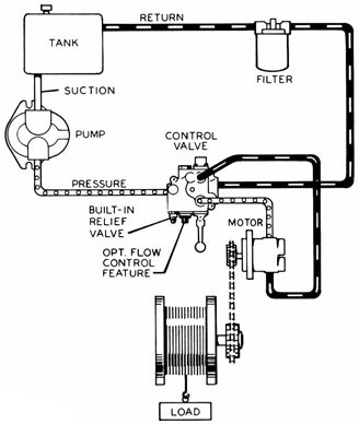
First of all you can see the electric motor driving the fixed delivery hydraulic pump in the above circuit. A safe pressure level is maintained using the pressure relief valve which is connected after the pump.
I. Fixed Displacement Pump – These pump has a set flow rate means every stroke of the motor moves same amount of fluid. Fixed displacement pumps are perfect for single jobs that to be repeated indefinitely over long periods of time. There are three types of fixed displacement pump : Gear Pump, Gerotor Pump, Screw Pump.
II. Variable Displacement Pump – In Variable displacement pumps flow rate and outlet pressure can be changed as the pump operates. They are used to power a wider variety of tool, but require more expense and more attention. There are four types of variable displacement pump: Bent Axis Pump, Axial Piston Pump, Radial Piston Pump, Rotary Vane Pump.
A hydraulic motor is a mechanical hydraulic actuator that converts hydraulic energy or hydraulic pressure into torque and angular displacement / rotation.
Hydraulic cylinder is a mechanical hydraulic actuator that converts hydraulic energy or hydraulic pressure into linear displacement. It consists of cylindrical barrel, piston and piston rod.
I. Pressure Relief Valve – They are designed to protect hydraulic system when pressure in the system increases beyond the specified design pressure or maximum working pressure. They are normally closed and it opens when the pressure exceeds a specified maximum value and diverts the pump flow back to reservoir or tank internally. They are located near hydraulic pump.
II. Pressure Reducing Valve – They are design to limit and maintain outlet pressure. They are normally open and closed if the pressure exceed beyond specified design pressure at outlet. They are located near hydraulic actuator.
IV. Counterbalance Valve – Counterbalance valves are used in hydraulic systems working with running-away or suspended load. They are designed to create backpressure at the return line of the actuator to prevent losing control over the load.
I. Check Valve– check valve or non return valve are simplest type of directional control valve used to allow free flow of fluid in only one direction.
They control the returning flow in relation to the flow being directed into opposite side of the actuator. It is used in hydraulic system to influence the speed of hydraulic motor and hydraulic cylinder independent to the load (prevent running away).
It is a electro mechanically operated valve. The valve is control by electric current through a solenoid. The function of solenoid valve in hydraulic system is to shut off, distribute and release fluid.

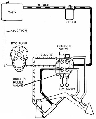
Operation of the system following actuation of the component depends on the type of selector valve being used. Several types of selector valves are used in conjunction with the open center system. One type is both manually engaged and manually disengaged. First, the valve is manually moved to an operating position. Then, the actuating mechanism reaches the end of its operating cycle, and the pump output continues until the system relief valve relieves the pressure. The relief valve unseats and allows the fluid to flow back to the reservoir. The system pressure remains at the relief valve set pressure until the selector valve is manually returned to the neutral position. This action reopens the open center flow and allows the system pressure to drop to line resistance pressure.
Closed-Center Hydraulic SystemsIn the closed-center system, the fluid is under pressure whenever the power pump is operating. The three actuators are arranged in parallel and actuating units B and C are operating at the same time, while actuating unit A is not operating. This system differs from the open-center system in that the selector or directional control valves are arranged in parallel and not in series. The means of controlling pump pressure varies in the closed-center system. If a constant delivery pump is used, the system pressure is regulated by a pressure regulator. A relief valve acts as a backup safety device in case the regulator fails.
If a variable displacement pump is used, system pressure is controlled by the pump’s integral pressure mechanism compensator. The compensator automatically varies the volume output. When pressure approaches normal system pressure, the compensator begins to reduce the flow output of the pump. The pump is fully compensated (near zero flow) when normal system pressure is attained. When the pump is in this fully compensated condition, its internal bypass mechanism provides fluid circulation through the pump for cooling and lubrication.A relief valve is installed in the system as a safety backup. [Figure 3] An advantage of the open-center system over the closed-center system is that the continuous pressurization of the system is eliminated. Since the pressure is built up gradually after the selector valve is moved to an operating position, there is very little shock from pressure surges. This action provides a smoother operation of the actuating mechanisms. The operation is slower than the closed-center system, in which the pressure is available the moment the selector valve is positioned. Since most aircraft applications require instantaneous operation, closed-center systems are the most widely used.
Evolution of Hydraulic SystemsSmaller aircraft have relatively low flight control surface loads, and the pilot can operate the flight controls by hand. Hydraulic systems were utilized for brake systems on early aircraft. When aircraft started to fly faster and got larger in size, the pilot was not able to move the control surfaces by hand anymore, and hydraulic power boost systems were introduced. Power boost systems assist the pilot in overcoming high control forces, but the pilot still actuates the flight controls by cable or push rod.
Many modern aircraft use a power supply system and fly-bywire flight control. The pilot input is electronically sent to the flight control servos. Cables or push rods are not used. Small power packs are the latest evolution of the hydraulic system. They reduce weight by eliminating hydraulic lines and large quantities of hydraulic fluid. Some manufacturers are reducing hydraulic systems in their aircraft in favor of electrically controlled systems. The Boeing 787 is the first aircraft designed with more electrical systems than hydraulic systems.
Hydraulic Power Pack SystemA hydraulic power pack is a small unit that consists of an electric pump, filters, reservoir, valves, and pressure relief valve. [Figure 4] The advantage of the power pack is that there is no need for a centralized hydraulic power supply system and long stretches of hydraulic lines, which reduces weight. Power packs could be driven by either an engine gearbox or electric motor. Integration of essential valves, filters, sensors, and transducers reduces system weight, virtually eliminates any opportunity for external leakage, and simplifies troubleshooting. Some power pack systems have an integrated actuator. These systems are used to control the stabilizer trim, landing gear, or flight control surfaces directly, thus eliminating the need for a centralized hydraulic system.
Below are some common illustrations of equipment located on fluids circuit diagrams, followed by descriptions of the most common elements. Later in this article series we will describe some simple hydraulic and pneumatic circuits composed of these circuit elements.
Hydraulic pumps are used to pump oil from the power unit to other parts of the hydraulic system. Some pumps have control options such as pressure or flow compensators.
Heat exchangers are used to remove heat from the circulating oil in the hydraulic system. The most common heat exchanger is water-to-oil but some times air-to-oil units are used. Coolers will cool the fluid.
Proportional valves are electrically controlled hydraulic valves. These valves proportionally control the hydraulic pressure and/or flow based on an electrical input signal.
For more information about reading hydraulic and pneumatic circuit diagrams, read the next article in this series which describes sample hydraulic circuits, or contact your Valmet representative.
A hydraulic pump is a mechanical device that converts mechanical power into hydraulic energy. It generates flow with enough power to overcome pressure induced by the load.
A hydraulic pump performs two functions when it operates. Firstly, its mechanical action creates a vacuum at the pump inlet, subsequently allowing atmospheric pressure to force liquid from the reservoir and then pumping it through to the inlet line of the pump. Secondly, its mechanical action delivers this liquid to the pump outlet and forces it into the hydraulic system.
The three most common hydraulic pump designs are: vane pump, gear pump and radial piston pump. All are well suited to common hydraulic uses, however the piston design is recommended for higher pressures.
Most pumps used in hydraulic systems are positive-displacement pumps. This means that they displace (deliver) the same amount of liquid for each rotating cycle of the pumping element. The delivery per cycle remains almost constant, regardless of changes in pressure.
Positive-displacement pumps are grouped into fixed or variable displacement. A fixed displacement pump’s output remains constant during each pumping cycle and at a given pump speed. Altering the geometry of the displacement chamber changes the variable displacement pump’s output.
Fixed displacement pumps (or screw pumps) make little noise, so they are perfect for use in for example theatres and opera houses. Variable displacement pumps, on the other hand, are particularly well suited in circuits using hydraulic motors and where variable speeds or the ability to reverse is needed.
Applications commonly using a piston pump include: marine auxiliary power, machine tools, mobile and construction equipment, metal forming and oil field equipment.
As the name suggests, a piston pump operates through pistons that move back and forth in the cylinders connected to the hydraulic pump. A piston pump also has excellent sealing capabilities.
A hydraulic piston pump can operate at large volumetric levels thanks to low oil leakage. Some plungers require valves at the suction and pressure ports, whilst others require them with the input and output channels. Valves (and their sealing properties) at the end of the piston pumps will further enhance the performance at higher pressures.
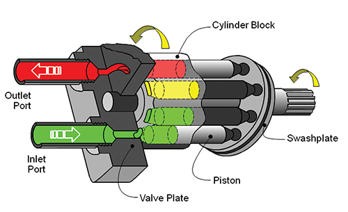
The axial piston pump is possibly the most widely used variable displacement pump. It’s used in everything from heavy industrial to mobile applications. Different compensation techniques will continuously alter the pump’s fluid discharge per revolution. And moreover, also alter the system pressure based on load requirements, maximum pressure cut-off settings and ratio control. This implies significant power savings.
Two principles characterise the axial piston pump. Firstly the swash plate or bent axis design and secondly the system parameters. System parameters include the decision on whether or not the pump is used in an open or closed circuit.
The return line in a closed loop circuit is under constant pressure. This must be considered when designing an axial piston pump that is used in a closed loop circuit. It is also very important that a variable displacement volume pump is installed and operates alongside the axial piston pump in the systems. Axial piston pumps can interchange between a pump and a motor in some fixed displacement configurations.
The swivel angle determines the displacement volume of the bent axis pump. The pistons in the cylinder bore moves when the shaft rotates. The swash plate, in the swash plate design, sustain the turning pistons. Moreover, the angle of the swash plate decides the piston stroke.
In general, the largest displacements are approximately one litre per revolution. However if necessary, a two-litre swept volume pump can be built. Often variable-displacement pumps are used, so that the oil flow can be adjusted carefully. These pumps generally operate with a working pressure of up to 350–420 bars in continuous work
Radial piston pumps are used especially for high pressure and relatively small flows. Pressures of up to 650 bar are normal. The plungers are connected to a floating ring. A control lever moves the floating ring horizontally by a control lever and thus causes an eccentricity in the centre of rotation of the plungers. The amount of eccentricity is controlled to vary the discharge. Moreover, shifting the eccentricity to the opposite side seamlessly reverses the suction and discharge.
Radial piston pumps are the only pumps that work continuously under high pressure for long periods of time. Examples of applications include: presses, machines for processing plastic and machine tools.
A vane pump uses the back and forth movement of rectangle-shaped vanes inside slots to move fluids. They are sometimes also referred to as sliding vane pumps.
The simplest vane pump consists of a circular rotor, rotating inside of a larger circular cavity. The centres of the two circles are offset, causing eccentricity. Vanes slide into and out of the rotor and seal on all edges. This creates vane chambers that do the pumping work.
A vacuum is generated when the vanes travel further than the suction port of the pump. This is how the oil is drawn into the pumping chamber. The oil travels through the ports and is then forced out of the discharge port of the pump. Direction of the oil flow may alter, dependent on the rotation of the pump. This is the case for many rotary pumps.
Vane pumps operate most efficiently with low viscosity oils, such as water and petrol. Higher viscosity fluids on the other hand, may cause issues for the vane’s rotation, preventing them from moving easily in the slots.
Gear pumps are one of the most common types of pumps for hydraulic fluid power applications. Here at Hydraulics Online, we offer a wide range of high-powered hydraulic gear pumps suitable for industrial, commercial and domestic use. We provide a reliable pump model, whatever the specifications of your hydraulic system. And we furthermore ensure that it operates as efficiently as possible.
Johannes Kepler invented the gear pump around year 1600. Fluid carried between the teeth of two meshing gears produces the flow. The pump housing and side plates, also called wear or pressure plates, enclose the chambers, which are formed between adjacent gear teeth. The pump suction creates a partial vacuum. Thereafter fluid flows in to fill the space and is carried around the discharge of the gears. Next the fluid is forced out as the teeth mesh (at the discharge end).
Some gear pumps are quite noisy. However, modern designs incorporating split gears, helical gear teeth and higher precision/quality tooth profiles are much quieter. On top of this, they can mesh and un-mesh more smoothly. Subsequently this reduces pressure ripples and related detrimental problems.
Catastrophic breakdowns are easier to prevent with hydraulic gear pumps. This is because the gears gradually wear down the housing and/or main bushings. Therefore reducing the volumetric efficiency of the pump gradually until it is all but useless. This often happens long before wear causes the unit to seize or break down.
Can hydraulic gear pumps be reversed? Yes, most pumps can be reversed by taking the pump apart and flipping the center section. This is why most gear pumps are symmetrical.
External gear pumps use two external spur gears. Internal gear pumps use an external and an internal spur gear. Moreover, the spur gear teeth face inwards for internal gear pumps. Gear pumps are positive displacement (or fixed displacement). In other words, they pump a constant amount of fluid for each revolution. Some gear pumps are interchangeable and function both as a motor and a pump.
The petrochemical industry uses gear pumps to move: diesel oil, pitch, lube oil, crude oil and other fluids. The chemical industry also uses them for materials such as: plastics, acids, sodium silicate, mixed chemicals and other media. Finally, these pumps are also used to transport: ink, paint, resins and adhesives and in the food industry.
Mathematical calculations are key to any type of hydraulic motor or pump design, but are especially interesting in the gerotor design. The inner rotor has N teeth, where N > 2. The outer rotor must have N + 1 teeth (= one more tooth than the inner rotor) in order for the design to work.
Hydraulic systems for lifting, lowering, or pulling can vary according to each individual project. There are many different configurations possible, so choosing the right components for your system should be done carefully to ensure a safe and successful outcome.
Important! For the inexperienced, understanding pressurized hydraulic systems can be complex. Every heavy-lift project has its own unique requirements and using the wrong set-up could be catastrophic. Please consult a suitably qualified and experienced person before you start work.
What follows is a simple introductory overview of how to configure a lifting system for anyone unfamiliar, or unaware of the options available. We’ve put together eight examples to get you started, ranging from simple hand pump cylinder sets to complex synchronous lifting systems.
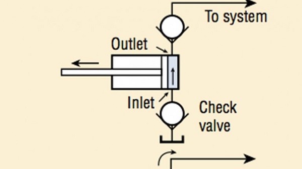
This diagram shows a very simple hydraulic system suitable for asingle-acting lifting application. Arrangements like this can be used in a wide variety of general-purpose maintenance situations, or in a hydraulic press.
It shows a manual hand pump for controlling the cylinder advance. (Note that this could be substituted for a powered pump). It’s worth knowing that a cylinder with a capacity of 25 ton and above may require many hand-pump strokes – especially for longer stroke applications.
Even in a simple setup such as this, using a pressure gauge is always recommended, as it gives a window into the hydraulic system. The Enerpac GA45GC 45® gauge assembly is perfect when using a hydraulic hand pump.
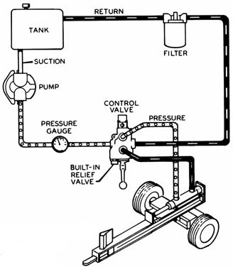
This shows another basic hydraulic system using asingle-acting hydraulic cylinder. This time it includes a cylinder with a longer stroke and an air-powered hydraulic pump.
When using any of our powered pumps (air/electric) we always recommend using our glycerine-filled gauges to reduce needle vibration for accurate pressure reading.
When lowering a heavy load it is sometimes important to have controlled retract. When this is a requirement, a system designed for a double-acting cylinder should be used. A double-acting cylinder uses hydraulics to lift or lower the load, unlike single-acting cylinders which rely on a return spring and gravity to retract the plunger. The latter can be time-consuming. (especially on longer stroke cylinders).
The above diagram shows a powered pump, but a hand pump may be used, however, please ensure the pump reservoir is sufficient to both fully advance and retract the cylinder(s).
Whenever you intend to use multiple cylinders – make sure the pump has a large enough reservoir to contain enough hydraulic fluid for the stroke of all the cylinders.
For long-term load holding applications, consider Enerpac hydraulic lock nut cylinders which mechanically lock off the load ensuring safe working in and around the area.
Safety Tip– Never work under a hydraulically suspended load. Always mechanically lock the load either by using cribbing blocks or mechanically operated locknut cylinders.
Split flow pumps offer many benefits for large-scale multi-point jacking applications. For lifting and lowering applications with multiple points, split flow pumps are a far better alternative than using independently operated pumps.
If you need more than 8 lifting points, they can be upgraded to network with additional split flow pumps – increasing the number of jacking locations up to an impressive 32 units!
For extreme accuracy applications, SFP-Series split flow pumps can be upgraded to become PLC-controlled synchronous lifting systems. This increases the SFP’s capabilities to become an accurate synchronous lifting/lowering system that’s capable of achieving +/-1mm accuracy from the leading/lagging hydraulic cylinder.
This upgrade utilizes external stroke sensors which communicate with the master control box to provide continuous feedback. Similarly, the upgraded SFP-Series Split Flow Pumps can also be networked to achieve an impressive 32 point synchronous lifting system – without the need to change any of the standard SFP hardware.
Network control boxes expand the number of lifting points by combining up to four split flow pumps together. This simplifies lifting operations by using a single operator station

It wasn’t until the beginning of the industrial revolution when a British mechanic named Joseph Bramah applied the principle of Pascal’s law in the development of the first hydraulic press. In 1795, he patented his hydraulic press, known as the Bramah press. Bramah figured that if a small force on a small area would create a proportionally larger force on a larger area, the only limit to the force that a machine can exert is the area to which the pressure is applied.
Hydraulic systems can be found today in a wide variety of applications, from small assembly processes to integrated steel and paper mill applications. Hydraulics enable the operator to accomplish significant work (lifting heavy loads, turning a shaft, drilling precision holes, etc.) with a minimum investment in mechanical linkage through the application of Pascal’s law, which states:
The principle of Pascal’s law is realized in a hydraulic system by the hydraulic fluidthat is used to transmit the energy from one point to another. Because hydraulic fluid is nearly incompressible, it is able to transmit power instantaneously.
The purpose of the hydraulic reservoir is to hold a volume of fluid, transfer heat from the system, allow solid contaminants to settle and facilitate the release of air and moisture from the fluid.
The hydraulic pump transmits mechanical energy into hydraulic energy. This is done by the movement of fluid which is the transmission medium. There are several types of hydraulic pumps including gear, vane and piston. All of these pumps have different subtypes intended for specific applications such as a bent-axis piston pump or a variable displacement vane pump. All hydraulic pumps work on the same principle, which is to displace fluid volume against a resistant load or pressure.
Hydraulic valves are used in a system to start, stop and direct fluid flow. Hydraulic valves are made up of poppets or spools and can be actuated by means of pneumatic, hydraulic, electrical, manual or mechanical means.
Hydraulic actuators are the end result of Pascal’s law. This is where the hydraulic energy is converted back to mechanical energy. This can be done through use of a hydraulic cylinder which converts hydraulic energy into linear motion and work, or a hydraulic motor which converts hydraulic energy into rotary motion and work. As with hydraulic pumps, hydraulic cylinders and hydraulic motors have several different subtypes, each intended for specific design applications.
There are several components in a hydraulic system that are considered vital components due to cost of repair or criticality of mission, including pumps and valves. Several different configurations for pumps must be treated individually from a lubrication perspective. However, regardless of pump configuration, the selected lubricant should inhibit corrosion, meet viscosity requirements, exhibit thermal stability, and be easily identifiable (in case of a leak).
There are many variations of vane pumps available between manufacturers. They all work on similar design principles. A slotted rotor is coupled to the drive shaft and turns inside of a cam ring that is offset or eccentric to the drive shaft. Vanes are inserted into the rotor slots and follow the inner surface of the cam ring as the rotor turns.
The vanes and the inner surface of the cam rings are always in contact and are subject to high amounts of wear. As the two surfaces wear, the vanes come further out of their slot. Vane pumps deliver a steady flow at a high cost. Vane pumps operate at a normal viscosity range between 14 and 160 cSt at operating temperature. Vane pumps may not be suitable in critical high-pressure hydraulic systems where contamination and fluid quality are difficult to control. The performance of the fluid’s antiwear additive is generally very important with vane pumps.
As with all hydraulic pumps, piston pumps are available in fixed and variable displacement designs. Piston pumps are generally the most versatile and rugged pump type and offer a range of options for any type of system. Piston pumps can operate at pressures beyond 6000 psi, are highly efficient and produce comparatively little noise. Many designs of piston pumps also tend to resist wear better than other pump types. Piston pumps operate at a normal fluid viscosity range of 10 to 160 cSt.
There are two common types of gear pumps, internal and external. Each type has a variety of subtypes, but all of them develop flow by carrying fluid between the teeth of a meshing gear set. While generally less efficient than vane and piston pumps, gear pumps are often more tolerant of fluid contamination.
Internal gear pumps produce pressures up to 3000 to 3500 psi. These types of pumps offer a wide viscosity range up to 2200 cSt, depending on flow rate and are generally quiet. Internal gear pumps also have a high efficiency even at low fluid viscosity.
External gear pumps are common and can handle pressures up to 3000 to 3500 psi. These gear pumps offer an inexpensive, mid-pressure, mid-volume, fixed isplacement delivery to a system. Viscosity ranges for these types of pumps are limited to less than 300 cSt.
Today’s hydraulic fluids serve multiple purposes. The major function of a hydraulic fluid is to provide energy transmission through the system which enables work and motion to be accomplished. Hydraulic fluids are also responsible for lubrication, heat transfer and contamination control. When selecting a lubricant, consider the viscosity, seal compatibility, basestock and the additive package. Three common varieties of hydraulic fluids found on the market today are petroleum-based, water-based and synthetics.
Petroleum-based or mineral-based fluids are the most widely used fluids today. These fluids offer a low-cost, high quality, readily available selection. The properties of a mineral-based fluid depend on the additives used, the quality of the original crude oil and the refining process. Additives in a mineral-based fluid offer a range of specific performance characteristic. Common hydraulic fluid additives include rust and oxidation inhibitors (R&O), anticorrosion agents, demulsifiers, antiwear (AW) and extreme pressure (EP) agents, VI improvers and defoamants. Additionally, some of these lubricants contain colorful dyes, allowing you to easily identify leaks. Because hydraulic leaks are so costly (and common), this minor characteristic plays a huge role in extending the life of your equipment and saving your plant money and resources.
Elevated temperatures cause the water in the fluids to evaporate, which causes the viscosity to rise. Occasionally, distilled water will have to be added to the system to correct the balance of the fluid. Whenever these fluids are used, several system components must be checked for compatibility, including pumps, filters, plumbing, fittings and seal materials.
When choosing a hydraulic fluid, consider the following characteristics: viscosity, viscosity index, oxidation stability and wear resistance. These characteristics will determine how your fluid operates within your system. Fluid property testing is done in accordance with either American Society of Testing and Materials (ASTM) or other recognized standards organizations.
Viscosity (ASTM D445-97) is the measure of a fluid’s resistance to flow and shear. A fluid of higher viscosity will flow with higher resistance compared to a fluid with a low viscosity. Excessively high viscosity can contribute to high fluid temperature and greater energy consumption. Viscosity that is too high or too low can damage a system, and consequently, is the key factor when considering a hydraulic fluid.
Viscosity Index (ASTM D2270) is how the viscosity of a fluid changes with a change in temperature. A high VI fluid will maintain its viscosity over a broader temperature range than a low VI fluid of the same weight. High VI fluids are used where temperature extremes are expected. This is particularly important for hydraulic systems that operate outdoors.
Aside from these fundamental characteristics, another property to consider is visibiilty. If there is ever a hydraulic leak, you want to catch it early on so you don"t damage your equipment. Opting for adyed lubricant can help you spot leaks quickly, effectively saving your plant from machine failure.
When selecting lubricants, ensure that the lubricant performs efficiently at the operating parameters of the system pump or motor. It is useful to have a defined procedure to follow through the process. Consider a simple system with a fixed-displacement gear pump that drives a cylinder (Figure 2).
Collect all relevant data for the pump. This includes collecting all the design limitations and optimum operating characteristics from the manufacturer. What you are looking for is the optimum operating viscosity range for the pump in question. Minimum viscosity is 13 cSt, maximum viscosity is 54 cSt, and optimum viscosity is 23 cSt.
Check the actual operating temperature conditions of the pump during normal operation. This step is extremely important because it gives a reference point for comparing different fluids during operation. Pump normally operates at 92ºC.
Using the manufacturer’s data for the pump’s optimum operating viscosity, find the value on the vertical viscosity axis of the chart. Draw a horizontal line across the page until it hits the yellow viscosity vs. temperature line of the lubricant. Now draw a vertical line (green line, Figure 5) to the bottom of the chart from the yellow viscosity vs. temperature line where it is intersected by the horizontal optimum viscosity line. Where this line crosses, the temperature axis is the optimum operating temperature of the pump for this specific lubricant (69ºC).
Repeat Step 8 for maximum continuous and minimum continuous viscosities of the pump (brown lines, Figure 5). The area between the minimum and maximum temperatures is the minimum and maximum allowable operating temperature of the pump for the selected lubricant product.
Find the normal operating temperature of the pump on the chart using the heat gun scan done in Step 2. If the value is within the minimum and maximum temperatures as outlined on the chart, the fluid is suitable for use in the system. If it is not, you must change the fluid to a higher or lower viscosity grade accordingly. As shown in the chart, the normal operating conditions of the pump are out of the suitable range (brown area, Figure 5) for our particular lubricant and will have to be changed.
The purpose of hydraulic fluid consolidation is to reduce complexity and inventory. Caution must be observed to consider all of the critical fluid characteristics required for each system. Therefore, fluid consolidation needs to start at the system level. Consider the following when consolidating fluids:
Hydraulic systems are complicated fluid-based systems for transferring energy and converting that energy into useful work. Successful hydraulic operations require the careful selection of hydraulic fluids that meet the system demands. Viscosity selection is central to a correct fluid selection.

Hydraulic systems are used in a wide range of applications today in hydraulic companies, from simple assembly operations to integrated steel and paper mills. Through Pascal’s law, the operator may achieve multiple tasks like lifting large weights, drilling precise holes, rotating a shaft, and so on, with a minimum investment in mechanical linkage.
The hydraulic fluid that is used to convey energy from one place to another embodies the idea of Pascal’s law in a hydraulic system. Hydraulic fluid can transmit power instantly because it is primarily incompressible.
The hydraulic reservoir’s role is to contain a fluid volume, transfer heat from the system, enable solid impurities to settle, and make air and moisture escape from the fluid easier. The industrial filters are located within the reservoir itself.
Mechanical energy is converted into hydraulic energy with the help of the hydraulic pump. The flow of fluid, which serves as the transmission channel, accomplishes this. Hydraulic pumps come in various shapes and sizes, including gear, vane, and piston. Different kinds of these pumps, such as a variable displacement vane pump or a bent-axis piston pump, are designed for various uses. The basic concept of all hydraulic pumps is to displace fluid volume against a resistive load or pressure.
Hydraulic valves are used to start, halt, and guide the fluid flow in a system. Pneumatic, hydraulic, electrical, manual, or mechanical actuation can be used to operate hydraulic valves formed up of poppets or spools.
Pascal’s law has resulted in hydraulic actuators. The hydraulic energy is transformed back to me


 8613371530291