
simple hydraulic pump diagram made in china
Electric hydraulic pumps are pray coating, anti-corrosion, pollution-resistant, durable. Lightweight and compact design make it easy to be moved. Double speed pump design, with the high flow in low pressure. The actuator can be fast moved on no-load status.Internal high and low pressure automatic reversing valve and external adjustable pressure valve to make it easy to calibrate the working pressure and avoid the over load. Motor starter has the function of preventing overload, overheat and leakage. The pump can be matched with both double acting and single acting cylinders. Choosing the solenoid valve electric hydraulic pump, remote operation can be realized.
The hydraulic components market in China (target market) is valued at approximately RMB 35 Bn in revenues as of year-end 2011(or RMB 37 Bn when including exports).
This study focuses on domestic sales of the four main hydraulic components used in hydraulic systems. These have been divided into the following product categories: hydraulic pumps, hydraulic cylinders, hydraulic valves and hydraulic motors.

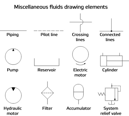
Below are some common illustrations of equipment located on fluids circuit diagrams, followed by descriptions of the most common elements. Later in this article series we will describe some simple hydraulic and pneumatic circuits composed of these circuit elements.
Hydraulic pumps are used to pump oil from the power unit to other parts of the hydraulic system. Some pumps have control options such as pressure or flow compensators.
Heat exchangers are used to remove heat from the circulating oil in the hydraulic system. The most common heat exchanger is water-to-oil but some times air-to-oil units are used. Coolers will cool the fluid.
Proportional valves are electrically controlled hydraulic valves. These valves proportionally control the hydraulic pressure and/or flow based on an electrical input signal.
For more information about reading hydraulic and pneumatic circuit diagrams, read the next article in this series which describes sample hydraulic circuits, or contact your Valmet representative.

The Betts Hydraulic Pump HP46982ALSL is designed as a corrosion resistant, reliable hydraulic pump for use with any Betts hydraulically operated valve or vent. The pump head and internal parts are made of corrosion resistant stainless steel. The reservoir is made of aluminum with a durable E-coating.
¼ NPT hydraulic connections are conveniently located at both the front of the pump and on the right side. A drain plug allows the reservoir to be drained without unbolting the pump.

A hydraulic pump converts mechanical energy into fluid power. It"s used in hydraulic systems to perform work, such as lifting heavy loads in excavators or jacks to being used in hydraulic splitters. This article focuses on how hydraulic pumps operate, different types of hydraulic pumps, and their applications.
A hydraulic pump operates on positive displacement, where a confined fluid is subjected to pressure using a reciprocating or rotary action. The pump"s driving force is supplied by a prime mover, such as an electric motor, internal combustion engine, human labor (Figure 1), or compressed air (Figure 2), which drives the impeller, gear (Figure 3), or vane to create a flow of fluid within the pump"s housing.
A hydraulic pump’s mechanical action creates a vacuum at the pump’s inlet, which allows atmospheric pressure to force fluid into the pump. The drawn in fluid creates a vacuum at the inlet chamber, which allows the fluid to then be forced towards the outlet at a high pressure.
Vane pump:Vanes are pushed outwards by centrifugal force and pushed back into the rotor as they move past the pump inlet and outlet, generating fluid flow and pressure.
Piston pump:A piston is moved back and forth within a cylinder, creating chambers of varying size that draw in and compress fluid, generating fluid flow and pressure.
A hydraulic pump"s performance is determined by the size and shape of the pump"s internal chambers, the speed at which the pump operates, and the power supplied to the pump. Hydraulic pumps use an incompressible fluid, usually petroleum oil or a food-safe alternative, as the working fluid. The fluid must have lubrication properties and be able to operate at high temperatures. The type of fluid used may depend on safety requirements, such as fire resistance or food preparation.
Air hydraulic pump:These pumps have a compact design and do not require an external power source. However, a reliable source of compressed air is necessary and is limited by the supply pressure of compressed air.
Electric hydraulic pump:They have a reliable and efficient power source and can be easily integrated into existing systems. However, these pumps require a constant power source, may be affected by power outages, and require additional electrical safety measures. Also, they have a higher upfront cost than other pump types.
Gas-powered hydraulic pump:Gas-powered pumps are portable hydraulic pumps which are easy to use in outdoor and remote environments. However, they are limited by fuel supply, have higher emissions compared to other hydraulic pumps, and the fuel systems require regular maintenance.
Manual hydraulic pump:They are easy to transport and do not require a power source. However, they are limited by the operator’s physical ability, have a lower flow rate than other hydraulic pump types, and may require extra time to complete tasks.
Hydraulic hand pump:Hydraulic hand pumps are suitable for small-scale, and low-pressure applications and typically cost less than hydraulic foot pumps.
Hydraulic foot pump:Hydraulic foot pumps are suitable for heavy-duty and high-pressure applications and require less effort than hydraulic hand pumps.
Hydraulic pumps can be single-acting or double-acting. Single-acting pumps have a single port that hydraulic fluid enters to extend the pump’s cylinder. Double-acting pumps have two ports, one for extending the cylinder and one for retracting the cylinder.
Single-acting:With single-acting hydraulic pumps, the cylinder extends when hydraulic fluid enters it. The cylinder will retract with a spring, with gravity, or from the load.
Double-acting:With double-acting hydraulic pumps, the cylinder retracts when hydraulic fluid enters the top port. The cylinder goes back to its starting position.
Single-acting:Single-acting hydraulic pumps are suitable for simple applications that only need linear movement in one direction. For example, such as lifting an object or pressing a load.
Double-acting:Double-acting hydraulic pumps are for applications that need precise linear movement in two directions, such as elevators and forklifts.
Pressure:Hydraulic gear pumps and hydraulic vane pumps are suitable for low-pressure applications, and hydraulic piston pumps are suitable for high-pressure applications.
Cost:Gear pumps are the least expensive to purchase and maintain, whereas piston pumps are the most expensive. Vane pumps land somewhere between the other two in cost.
Efficiency:Gear pumps are the least efficient. They typically have 80% efficiency, meaning 10 mechanical horsepower turns into 8 hydraulic horsepower. Vane pumps are more efficient than gear pumps, and piston pumps are the most efficient with up to 95% efficiency.
Automotive industry:In the automotive industry, hydraulic pumps are combined with jacks and engine hoists for lifting vehicles, platforms, heavy loads, and pulling engines.
Process and manufacturing:Heavy-duty hydraulic pumps are used for driving and tapping applications, turning heavy valves, tightening, and expanding applications.
Despite the different pump mechanism types in hydraulic pumps, they are categorized based on size (pressure output) and driving force (manual, air, electric, and fuel-powered). There are several parameters to consider while selecting the right hydraulic pump for an application. The most important parameters are described below:
Speed of operation: If it is a manual hydraulic pump, should it be a single-speed or double-speed? How much volume of fluid per handle stroke? When using a powered hydraulic pump, how much volume per minute? Air, gas, and electric-powered hydraulic pumps are useful for high-volume flows.
Portability: Manual hand hydraulic pumps are usually portable but with lower output, while fuel power has high-output pressure but stationary for remote operations in places without electricity. Electric hydraulic pumps can be both mobile and stationary, as well as air hydraulic pumps. Air hydraulic pumps require compressed air at the operation site.
Operating temperature: The application operating temperature can affect the size of the oil reservoir needed, the type of fluid, and the materials used for the pump components. The oil is the operating fluid but also serves as a cooling liquid in heavy-duty hydraulic pumps.
Operating noise: Consider if the environment has a noise requirement. A hydraulic pump with a fuel engine will generate a higher noise than an electric hydraulic pump of the same size.
Spark-free: Should the hydraulic pump be spark-free due to a possible explosive environment? Remember, most operating fluids are derivatives of petroleum oil, but there are spark-free options.
A hydraulic pump transforms mechanical energy into fluid energy. A relatively low amount of input power can turn into a large amount of output power for lifting heavy loads.
A hydraulic pump works by using mechanical energy to pressurize fluid in a closed system. This pressurized fluid is then used to drive machinery such as excavators, presses, and lifts.
A hydraulic ram pump leverages the energy of falling water to move water to a higher height without the usage of external power. It is made up of a valve, a pressure chamber, and inlet and exit pipes.
A water pump moves water from one area to another, whereas a hydraulic pump"s purpose is to overcome a pressure that is dependent on a load, like a heavy car.
Hydraulic pump motor units assembled with electrical motor and hydraulic gear pumps. They are simple hydraulic pump system without hydraulic tanks. Hydraulic pump and motor system driven by electrical motors. Each hydraulic pumps and motors unit is designed and manufactured by
Hydraulic pump & motor systems with powerful 12V DC and 24 V DC motors complete with an hydraulic gear pump creating pressure up to 300 bar and flow up to 20 L/min. Each
These small DC electric hydraulic pump systems assembly with a fan-cooled electric DC motor and aluminum hydraulic gear pumps. Each hydraulic motor and pump system offers flow up to 32 L/min and pressure up to 210 bar. The fan-cooled part make hydraulic motor pump system DC motors work duty S2 and S3 possible.
Our wide range of AC motors voltage come with AC110V,AC220v,240v,AC380V,AC415V, single-phase and three-phase; electric power from 0.37kw up to 3Kw. 50Hz or 60Hz. And customized AC hydraulic pumps and motors system are available.
Each AC hydraulic pump motor is available with a hydraulic gear pump, which can be fitted to offer hydraulic fluid pressures to 250 bar and hydraulic fluid flows to 55 L/min.

The SKS Hydraulic TECHNOLOGY Co., Ltd was established (as the Ningbo WIDESKY SKS Hydraulic CO., LTD.) is located inZhejiang ,China. SKS is an advanced National Torch Plan enterprise and ISO 9001:2008 certified. SKS specializes in manufacturing five major hydraulic product lines: piston pumps/motors/spare parts; swing and travel motors with gearbox reducers; gears and charge pumps for piston pumps; control valves; and precision castings.
Over more than10years of development, SKS has become an internationally reputed brand name in the field of hydraulics and a world-ranking manufacturer of a wide range of hydraulic products. SKS possesses its own independent innovative manufacturing system and technology. It has over 400 units of advanced automatic production machinery, including precision casting lines and bi-metal sintering furnaces. These advanced manufacturing facilities combined with rigorous quality control have contributed to SKS achieving a leading position within the domestic Chinese hydraulic industry.
SKS has its own high-level Hydraulic Research and Development Center. Having 20% of the total workforce made up of professional hydraulic experts, research workers, engineers and technicians helps to build a strong competent R&D team. SKS has collaborated with prominent Chinese universities on R&D and manufacturingprojects for piston pumps, motors, reduction gears and valves.
SKS’s business philosophy is to offer excellent quality, great variety and prompt service to satisfy its customers’ needs. The management has made market-orientation, quality and innovation its core values and aims to take the Chinese national hydraulic industry to new heights.
Target Hydraulics has over 10 years of experience in mini hydraulic power unit Engineering.&Manufacturing, We can supply you with any type of hydraulic power packs for your AC&DC hydraulic power units market.
AC motor hydraulic power unit from 0.5 hp to 5 hp hydraulic power unit even 10 hp hydraulic power unit.DC motor hyd power unit(HPU) from 0.15kw up to 3Kw even 4.5Kw.
Target Hydraulics manufactures compact hydraulic power units that can meet hydraulic flow rating from 0.3LPM to 30LPM based on your compact hydraulic power unit needs.
Target Hydraulics can provide you hydraulic power unit design with different working pressure from 20bar up to 315bar based on your custom hydraulic power units request.
All Target Hydraulics hydraulic block manifold designing&manufacturing with standard valve body cavity. We can also supply you valve cavity tooling if you are custom hydraulic power unit manufacturers.
All hydraulic power units and parts were designed with 3D software for your new project. Professional hydraulic power unit sales and manufacture team guarantee your hyd power unit order processing quick and superior quality.
Hydraulic Manifolds 3D drawing design and CNC machine for quick sample delivery.7/24 no-stop CNC machine line,3000sqm warehouse,8 assembly lines, and test benches,50+ professional staff provide your hyd power units and parts always delivered on time.
Our engineers create small hydraulic power units and hydraulic manifold designs with Solidworks. Our DC and AC hydraulic power pack units and hydraulic cartridge valves are used for industry hydraulics, truck hydraulics, mobile hydraulics, custom hydraulic manifolds, and many other different Hydraulics applications.
Target Hydraulics provides high quality products and good service for our clients and distributors around the world. You hit your target at Target Hydraulics.
DC hydraulic power unit and AC hydraulic power unit. All the electric hydraulic power units will complete with an electrical motor, whatever the motor is DC or AC voltage.
Hydraulic power units were designed can be applied to anything that requires lift,push, and rotational applications, They are utilized in a wide variety of agricultural, material handling, industrial and mobile applications and so much more.
scissor lift, dump trailer hydraulic system unit,forklift hydraulics, plant dump trailers, dump trucks, and even security equipment like access control.
Hydraulic power units should be able to supply the needed power to drive machinery in every movement or direction. All hydraulic power unit working principles follow Pascal’s pressure working mechanism.
Basic components of a hydraulic power pack unit include a diesel or electric powered motors, hydraulic reservoirs, couplings and fittings, suction pipes and filters, hydraulic valves, and hydraulic gear pumps, as well as hydraulic block manifolds.
For example, a small hydraulic power unit has fewer hydraulic components in comparison to hydraulic power units that are utilized in the big heavy lifting industries applications.
A hydraulic power unit has different types of valves in its system. These valves are essential for controlling the hydraulic fluid flow and pressure within a hydraulic power pack hydraulic system.
The following are the types of valves that are mostly used in a hydraulic power supply system. Each type of valves in the list has different functions, depending on the design and application requirement.
StackedValves – Stacked valves are responsible for making the flow of hydraulic transmission changing hydraulic pressure. These valves are mounting attached to the hydraulic central manifolds channel together with the stacked block manifolds.
Check Valves – Check valves keep pressure from the hydraulic pump to the hydraulic cylinder and hold pressure for the single acting hydraulic power unit. These check valves designed with different cracking pressure.
Throttle Valves – Throttle valves also called flow control valve, they are used to open, close,start stop, or regulate the hydraulic oil fluid flow by a dynamic pump.
Directional ControlHydraulicValves – are used to retract or extend double-acting hydraulic cylinders or hydraulic motors. These directional valves provide a directional path from pump to cylinders (hydraulic motors) and a return path from cylinders (hydraulic motors) to the hydraulic fluid oil tank.
A hydraulic reservoir or tank stores the hydraulic fluid for a hydraulic system. The tank is also the key to transfer heat for this hydraulic power unit system.
Without the tank, air moisture will cause problems in your hyd power unit. The heat in the hydraulic tank releases rises the moisture above the hydraulic oil fluid making its way out of the tank through the hydraulic tank air breather cap.
The typical materials used in hydraulic tanks come from steel, stainless steel, and aluminum. the mini hydraulic power unit also used plastic materials as their hydraulic tank reservoir.
With the center manifold, you can assemble motors, pumps, hydraulic valves to complete a hydraulic power unit. There will be hydraulic fluid pressure oil go through the central manifold if this is a small hydraulic power unit design.
There are three major types of hydraulic pumps:Gear Pump– Intervals of gears are used to pump fluids by motion. In each revolution, it pumps a fixed amount of high viscosity fluids.
Piston Pump– Piston pumps are displacement pumps that create pressures and discharge fluid with little effort. The pressure this pump creates pressurized the fluid in the hydraulic system.
Vane Pump– Vane pumps have rectangular-shaped vanes inlets. The back and forth rotation of these vanes moves pressure against the outer face of the ring, making the vane pump work.
The features of gear pumps are simple and compact. Because of having limited numbers of motion components, it cannot compete with reciprocating or centrifugal pumps when it comes to generating pressure and flow. However, it generates higher pressure and flow rate compared to vane pumps.
The common materials used in making gear pumps include iron, alloy, aluminum, and composites. The type of materials is essential in dealing with corrosive liquids.
Having a priming characteristic means gear pumps need lubrication and should not be dry. Close tolerance of gears and casting can wear the pump over time.
The precise specifications between the gears and casing enable the pump to develop suction at the inlet, this will prevent fluid leakage from the discharge place.
An internal gear pump still has two interlocking gears. However, in comparison to the external pump’s identical gears, the gears of internal pumps have different sizes. A smaller gear is mounted at the center of the larger gear.
This is specifically designed to interlock with the gear teeth attached at one point. And a pinion and bushing are engaged at the pump’s casing holding the idler gear in its place.
In contrast with fixed-displacement pumps which have two chambers, a variable displacement pump only has a single chamber. The movement of the outer ring to the inner enables the pump to work.
In applications these two and be reversible. For instance, if it’s powered by a motor and pressure flow is output, it is a hydraulic pump; if the flow of oil pressure is input and the torque energy is output, it’s a hydraulic motor.
This type of cylinder has only one end port that is utilized to supply and vent compressed air. Therefore, hydraulic fluid in a single-acting hydraulic cylinder works only on one side of the piston.
Hydraulic fluid oil can either be synthetic or mineral-based liquid. Common variations of mineral-based hydraulic fluid are petroleum-based and water-based fluids. Some fluids consist of plain water, water-oil emulsions, and even salt solutions.
Hydraulic oil fluid is the ingredient used the hydraulic systems to transfer power in hydraulic machinery and equipment. Hydraulic liquids are additionally in charge of lubrication, warmth transfer, and contamination control within the system.
Its principle is about the principle of off-line filters. The hydraulic fluid oil will be filtered by the hydraulic filter. Then after its filtration, it will be pumped out through the outlet port or back to the tank. Hydraulic filters are placed either on a suction port of the pump or tank port into the reservoir.
Electrical power is usually not needed in order to operate a hydraulic system. The fundamental rule of a hydraulic system is the use of liquid in its operations.
Hydraulic power units have some technical selective components that need precise consideration during design. This is crucial to ensure that the unit will work properly after its setup.
However, credentials or certification are not a must when setting up a hydraulic power unit. Even so, you must have the proper knowledge and ability when dealing with it so that the components will be installed precisely. If it is your first time, collaborate with an experienced installer to accomplish your desired result.
Examination of the hydraulic system after installing should be taken into account. This is important to ensure hyd power unit system working properly.
Make sure there are no debris, chips, or any foreign objects in the valve and hydraulic block manifolds. The O-rings should also be check for cleaning and quality station.To avoid damage during installation, lubricate the O-rings on the cartridge valve.
It’s advisable to use hydraulic oil for lubrication. Grease and motor oil should not be applied for it will mix with the hydraulic fluid and gum up the valves.
Some hydraulic power units remotes are wireless remote, enabling you to control the start and the stop of your hydraulic power units without cables or switches. Remote buttons are controlling the hydraulic cylinder in and out motion.
Follow these sequences. Connect hydraulic power unit and cylinder with hydraulic hoses. Connect both A and B oil ports with cylinder A and B ports.First, take one side of the hose, connect the hydraulic hose one side to the base of the hydraulic cylinder. Then the other side of the hydraulic hose must be connected to the rod end of the hydraulic cylinder.
While testing or operating the hydraulic power pack unit, keep an eye on the fluid level of the tank. The level of the hydraulic fluid should not have lowered down half full during the trial start-up. Do not let the suction filter out of hydraulic fluid.A fully extended cylinder’s tank should be half full. If you will let the hydraulic fluid drop below half full of its initial level, air might enter into your hydraulic system. This can lead to aeration of the fluid and it could overflow the reservoir tank.
If this is the problem, the possible causes are the following:Hydraulic reservoir is short of oil; add the required level of oil into your hydraulic unit’s tank.
General maintenance for hydraulic power unit includes lubricating electric motors, cleaning or changing hydraulic oil fluid, and cleaning of the suction strainers.
The oil of the tank should also be regulated. Always check if the oil level of the tank to avoid an existential drop. Changing oil is also necessary, to keep your hydraulic power unit in good performance.
Then what significant size of a hydraulic power unit is suitable for your job. Also, include the liquid flow rate when deciding what size of hydraulic power pack unit you want to get.
The number of outlets and inlets of the should also be taken into account. This is certainly important you can utilize the amount of power you going to use. Then come with hydraulic oil port question, BSPP, SAE, and Metric units are all available from Target Hydraulics Power Units.

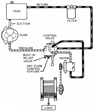
A directional control valve with optional pressure kickout feature controls a double acting cylinder. A pressure gauge is recommended to help spot potential system problems. The tank should be at least one and a half times the pump gpm output and the oil level must remain above the pump intake at all times. (See Logsplitter Safety for more detailed information.)
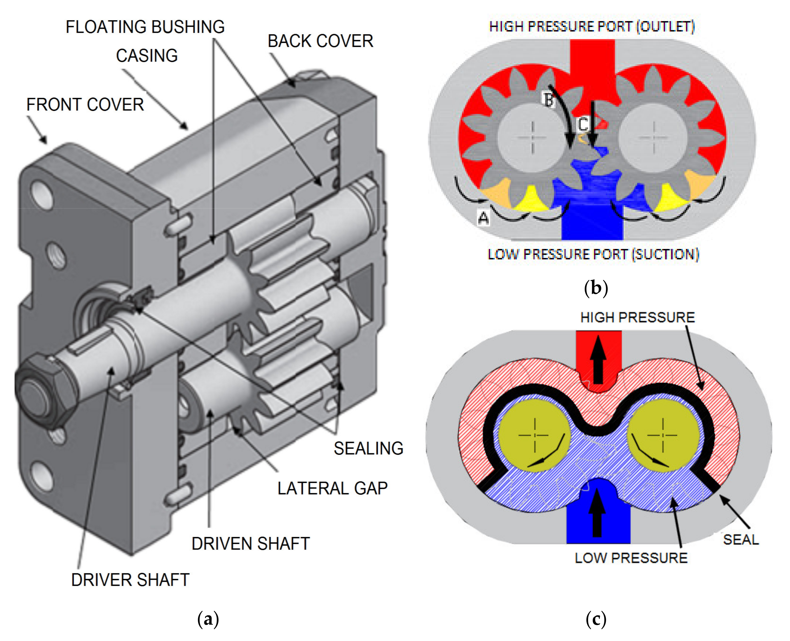
The external gear pump technology is a type of positive displacement pump. External gear pumps simply use the actions of gears to transfer different types of fluids. In this article, we will illustrate the main features of external and internal gear pumps, the way they work, and other technical information. Finally, we will briefly introduce the external gear pumps produced
• an external gear pump utilizes two identical gears meshed side by side, where one gear (driving) is driven by a motor, and it – in turn – drives the other one, the idle (driven) gear. Each gear is supported by a shaft with bearings on both sides of the gear. Fluid trapped between the gear teeth is transported from the inlet to outlet ports, with the gear mesh acting as a seal between the ports.
• aninternal gear pumputilizes two meshing gears with the outer (ring) gear typically driving the inner (idler) gear. Fluids trapped between the gears are transmitted from the inlet to the outlet port due to the rotation of the meshing gears, with the gear mesh typically acting as a seal between the ports. An internal gear pump will often use a crescent component to assist in the internal sealing of the gears.
In the external gear pumps the two gears mesh with each other in a close fitting housing. As the gears rotate, fluid fills the space between corresponding gear teeth and is carried from the inlet side to the outlet around the external circumference of the gears. Where the teeth mesh together, fluid cannot pass and so it is ejected through the outlet.
• External helical gears: helical gears utilize “angled” gears, that is each gear tooth has an identical helix angle (referenced to the axis of rotation) such that the contact ratio of the gear mesh is always greater than 1. A higher contact ratio is beneficial in that two gears are often sharing the load during operation. Typically the helix angle for a pump gear is less than 5 degrees to maintain good hydraulic efficiency.
Thanks to their versatility, resistance, and technical features, external gear pumps offer advantagesthat are renowned in all their application fields.
Fluid-o-Tech is a market leader in the design and production of external gear pumpsand internal gear pumps. At the core of our work, we have chosen to build long-lasting relationships of trust with our Customers, becoming their technology partner for the newest developments.
Fluid-o-Tech external gear pump technology has proven to be the most reliable, efficient,and robustpump technology over the years for use within different applications and industries. Among our product types that are worth mentioning, you should consider:


 8613371530291