
slurry tanker hydraulic pump free sample
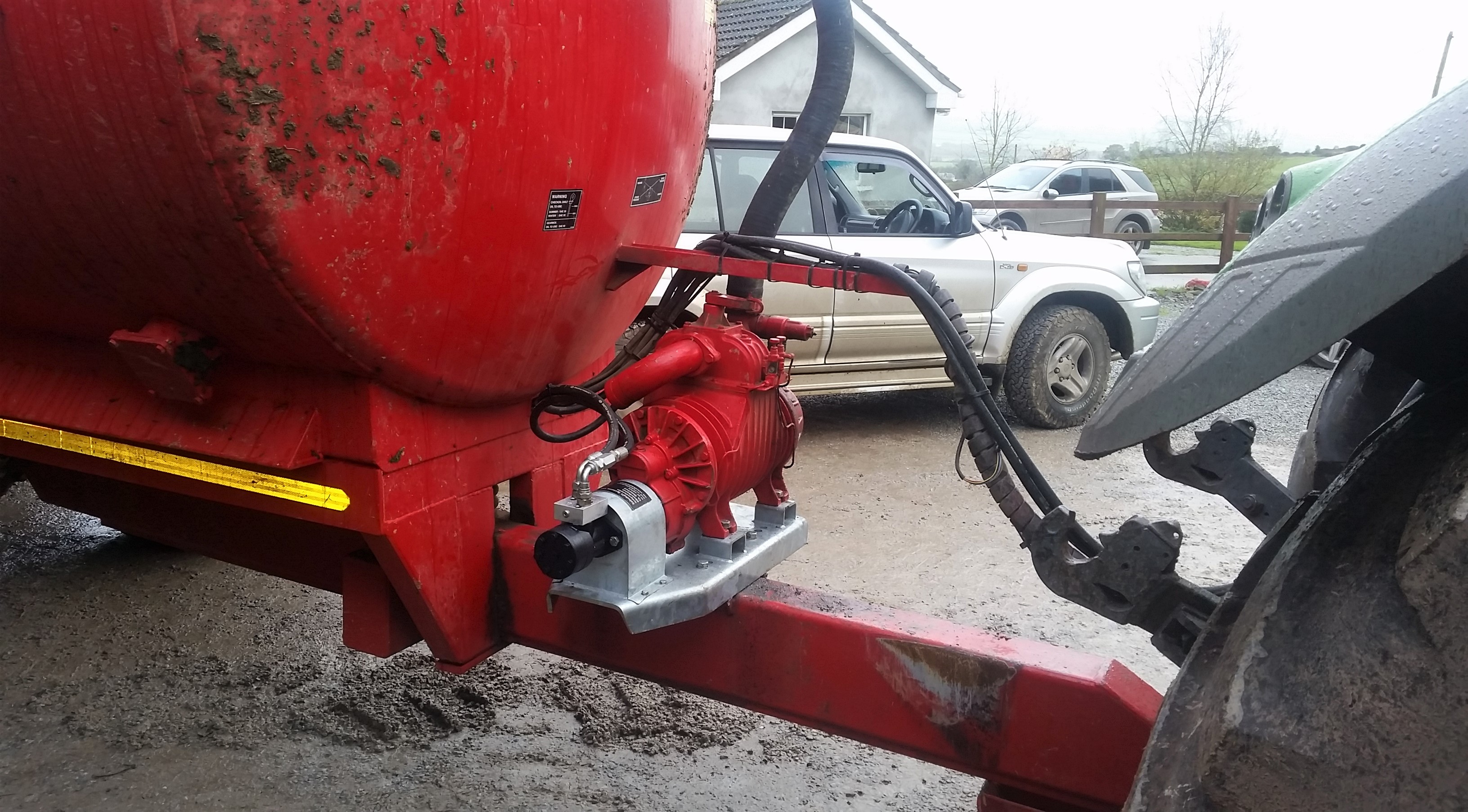
Located outside the village of Kilmacthomas, Co Waterford, brothers Noel and Ger Hickey are the men behind the patented Safeshaft System. For those unfamiliar with Safeshaft, it’s essentially a hydraulic drive system which replaces the conventional PTO shaft used to power vacuum pumps on slurry tankers.
Noel is an agricultural mechanic running his own business while Ger runs his own metal fabrication shop. In 2015, the brothers were approached by a neighbour to see if they could design a solution to replace the standard PTO shaft on his slurry tanker. The duo got to work.
What you see with the Safeshaft is what you get. The concept is to remove the PTO shaft, transferring the drive from the tractor’s PTO to the tanker’s pump.
Obviously, this is the most dangerous part of the slurry tanker, which is due to its high speed of rotation (nine revolutions per second) and close proximity to people.
The Hickey brothers have fitted a hydraulic motor in place of the PTO shaft. This is powered by the tractor’s hydraulic system through a double-acting spool valve. The return line is fitted with a non-return valve to stop the pump being run in reverse accidentally. To allow the pump to start slowly and to prevent shock engagement and disengagement, an anti-cavitation block is fitted which alters the oil flow on start-up and stopping, making it smoother.
The power is transferred from the motor to the pump via a steel coupler with a shock absorber that can allow for up to 4° of misalignment and is fully guarded for safety.
Depending on the brand of slurry tanker and pump, the pump may need to be moved rearwards or mounted crossways so that the hydraulic motor is out of reach of the tractor’s lift arms.
1 For starters, the PTO shaft and PTO cover need to be removed. Next, the four bolts securing the vacuum pump to the tanker chassis need to be removed. Once these bolts are removed, the pump needs to be lifted upwards using a loader or similar.
2 Once there’s enough clearance, the new galvanised base plate specific to the particular pump needs to be slid into place and bolted down to the original mounting plate on the tanker’s chassis. Most base plates are also designed to be mounted crossways on the drawbar if desired. Either way, these bolts need to be tightened correctly.
3 The next step is to seat the pump in position on the new base plate. Fasten the bracket to the face of the pump using the holes in the bracket which correspond with the holes on the face of the pump previously used for mounting the PTO guard. Longer bolts than the previous PTO guard bolts may be needed.
4 Next up, the hydraulic motor and coupler needs to be placed on to the pump shaft and mounted to the front plate with the anti-cavitation valve facing upwards. Once the motor has been fastened to the front plate, square the vacuum pump up on the new base plate and fasten the pump via the four bolts.
5 When the pump and base plate is fastened, tighten the coupler’s hex bolts on both the vacuum pump and hydraulic motor side. At this stage the parking brake will need to be fitted which will involve drilling the base plate to suit the particular bracket.
6 Although the pipe work comes readymade, it needs to be plumbed. Where a hose arm is fitted, try to route the flow and return pipes so that they are alongside existing hydraulic hoses. If fitted with the shut-off valve, make sure pipe work is plumbed according to the diagram provided. It is essential that the one-way valve is fitted on the return line to prevent the pump being operated in reverse.
The manual shut-off lever is designed to stop the vacuum pump at ground level. Once engaged, oil is diverted back through the return causing the pump to cut out. When the spool has been re-engaged, the lever will automatically return to its working position.
Secondly, it cuts out the possibility of damaging an expensive wide-angle PTO shaft with the lift arms. This also means the tractor can turn tighter against the tanker’s drawbar.
The brothers currently have over 70 units to date working throughout Ireland and the UK. It’s worth noting that this design isn’t solely limited to slurry tankers, but can also be fitted to PTO powered implements which do not require huge amounts of power to drive. One such example is sprayers, which the Hickeys have a number of hydraulic drives fitted too.
The big question some readers will have is what is the hydraulic requirement, and will I have enough capacity to simultaneously run both the hydraulic pump and the macerator on a low-emission slurry spreading (LESS) system. According to the Hickeys, when filling the tanker, the system needs 28 l/min, while to spread it needs 20 l/min.
In terms of running a macerator, most will work on 30-35 l/min. This means total oil flow will be in the region of 50-60 l/min, which would be within the capability of the vast majority of tractors which are given the task of operating a tanker and LESS system.
The Hickeys explained that they cater for all tanker manufacturers, with kits on the shelf ready for delivery. Depending on the tanker, there are numerous options available to suit individual requirements, such as manual or electric flow control valves, in-cab speed display and in-line filters.
Depending on brand, a new standard shaft will cost in the region of €250-280 while a wide-angle shaft will cost somewhere in the region of €650. Most slurry tankers will require at least one replacement shaft throughout their lifetime.

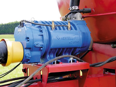
The part on a slurry tanker that does the most amount of work and is subject to the most wear and tear is undoubtedly the vacuum pump. It works on the principle of removing the air from the tank which creates a vacuum which in turn sucks up the slurry. The pump is also used in reverse to push air back into the tank creating pressure which will spread the liquid once the gate valve is opened.
The vacuum pump normally used is a rotary vane pump which consists of vanes mounted into a rotor that rotates inside of a cavity or chamber. The centres of the two rotor ends are offset, causing eccentricity. The vanes are allowed to slide in and out of the rotor and seal against the edges which creates vane chambers that do the pumping work. Over time especially if not maintained correctly the vanes inside the pump can wear, break or become stuck inside the rotor slots which will drastically reduce the pumps ability to work efficiently and often stop it working altogether.
All vacuum pumps should be fitted with an oiler which drops lubricating oil into the rotor at a rate of at least 1 drop every 2 seconds. This oil lubricates the vanes, only a light grade of oil such as pump oil or hydraulic oil should be used. Take care not to let dirt in when filling by cleaning around the area beforehand. Good practice particularly when working with watery slurry is to suck up a cup full of diesel into the pump when finished which will coat the vanes and stop them sticking. Best practice is to try rotate the pump by hand before attaching the PTO shaft; this will allow you the opportunity to identify a potential problem such as a stuck vane before applying the tractors power to it which may potentially cause more damage. If the pump doesn’t rotate freely you should free it by hand using the PTO shaft at 90 degrees for leverage. If it doesn`t move you will have no choice only open it to fix the problem. Another sign that there is an internal issue with the pump is that the sound may be different from the normal note, the suction performance may be reduced or worst case scenario it won`t work at all.
In this article I am going to take a step by step look at how to replace the vanes and rebuild your pump which is a relatively simple job which many farmers can do themselves.
The vacuum pump is attached to the draw=bar of the tanker normally with 4-6 bolts. The best practice is to wash the pump with a high pressure washer before working on it as it will make the job much easier not to mention cleaner. In some cases you can rotate the pump to gain access to the rear of it to remove the rotor however the best practice is to remove it completely and put it onto a bench at waist height to work on. Take care when removing the pump as it is quite heavy and should only be lifted with a suitable machine such as a forklift.
The oiler is a critical part of the pump to ensure it stays working efficiently. When the pump is on the bench it is often a good opportunity to clean the oil system making sure it is working correctly. Remove the bolts holding the oil pump to the vacuum pump and remove it taking care not to lose the small drive piece.
Replacement oiler kits are available starting at €70 + Vat. These kits will consist of a new oil pump, oilers, pipes and all the necessary gaskets to refit.
When refitting the oil pump take extra care that the drive is in place and aligned correctly. Failure to do so may bend or break the drive attachment and stop the oiler working. This is a common mistake that people make so extra care should be taken when refitting.
To remove the rotor the pump will need to be rotated 180 degrees to the input shaft and gearbox end. Drain the oil in the gearbox into an appropriate container and dispose of it correctly. Once drained remove the studs and again use longer bolts to remove the gear casing.
Once the slots are cleaned and sanded the next step is to fit the new vanes. When fitting them firstly lightly coat them with pump oil before assembling making sure that they are free to slide in and out of the slots. Vanes that stick or are tight will cause the pump to not run correctly causing problems or damage so it’s vital that this step is adhered to correctly.
Over time the vanes will inevitably wear due to the friction between them and the chamber wall which creates the seal and allows the pump to work. New vanes are relatively inexpensive with prices on average starting at €10 + Vat each.
Once the vanes are fitted it’s simply a matter of reversing the process to reassemble it. Make sure that all surfaces are clean and dry replacing all gaskets and seals necessary. Refill the gearbox with good quality oil such as SAE 90 gear oil. Refill the pump oiler with clean good quality pump oil or alternatively any light oil such as hydraulic oil. Once assembled turn the pump by hand a number of full rotations to ensure everything is working correctly before running the tractors power through it.
While you are working on the pump it is also a good opportunity to check it over in relation to other components such as the pressure relief valve which is a vital safety feature.
To make life easier you can purchase complete rebuild kits to suit the make and model of the pump fitted to your tanker. These kits range in price from €120 + Vat upwards and contain everything you need to do it yourself.
The most important thing when ordering the kit to suit your pump is to obtain the correct make and model of it as well as the serial number which should be stamped into the casing. This will ensure that you get the exact and correct parts needed to do the complete rebuild.
A small amount of time, some basic mechanical know how and standard tools commonly found in any farm workshop will allow you to refurbish your pump yourself at home in order to obtain many more years reliable service while helping to save you money.

Equipped with full hydraulic operation from the tractor cab, the new Slurry Buggy frees the tractor driver from the task of wrestling with messy pipes and couplings. He simply positions the tanker alongside the slurry pit. Then, using hydraulic controls, swings out the 8-in. dia. filling probe, which sucks the tank full, closes itself off, and swings back up into field position.
The 2,900 gal. tanker wagon fills itself in just 4 min. "An operator could easily spend 3 to 4 minutes with valves and couplings on a manual system so we"re able to cut loading time in half," says Zimmerman, noting that the tanker is also fitted with "peace of mind" features such as up-front indicators that tell if the hydraulic valve at back has closed completely and a level indicator that tells how much is in the tank.
Then tank is made from heavy 5/16-in. steel and features the largest vacuum pump available. Zimmerman designed his own filtering system for the pump that he says practically eliminates maintenance.
The Slurry Buggy unloads through a hydraulically-opened 6-in. dia. rear valve. Pressure is reversed in the tank to blow out the manure and it"s spread in up to a 50-ft. swath by an adjustable deflector plate. Zimmerman also offers a toolbar fitted with shanks for injecting manure below ground.
"There are no bearings, chains and or other moving parts that come in contact with the manure so maintenance is kept to a minimum. And, because we"ve got the thickest tank and largest pump on the market we think it"ll"be the longest lasting slurry tank ever built," says Zimmerman, a farmer who"s just getting into manufacturing. The tank has a 20-in. dia. rear manhole that"s located at the rear rather than on top for easy clean-out.
Self-Load Slurry Wagon MANURE HANDLING Equipment 9-1-2 "So far as we know, it"s the first self-filling vacuum slurry tanker on the market in the U.S. or Canada," says Larry Zimmerman, Ephrata, Penn., manufacturer of the "Slurry Buggy".Equipped with full hydraulic operation from the tractor cab, the new Slurry Buggy frees the tractor driver from the task of wrestling with messy pipes and couplings. He simply positions the tanker alongside the slurry pit. Then, using hydraulic controls, swings out the 8-in. dia. filling probe, which sucks the tank full, closes itself off, and swings back up into field position.The 2,900 gal. tanker wagon fills itself in just 4 min. "An operator could easily spend 3 to 4 minutes with valves and couplings on a manual system so we"re able to cut loading time in half," says Zimmerman, noting that the tanker is also fitted with "peace of mind" features such as up-front indicators that tell if the hydraulic valve at back has closed completely and a level indicator that tells how much is in the tank.Then tank is made from heavy 5/16-in. steel and features the largest vacuum pump available. Zimmerman designed his own filtering system for the pump that he says practically eliminates maintenance.The Slurry Buggy unloads through a hydraulically-opened 6-in. dia. rear valve. Pressure is reversed in the tank to blow out the manure and it"s spread in up to a 50-ft. swath by an adjustable deflector plate. Zimmerman also offers a toolbar fitted with shanks for injecting manure below ground."There are no bearings, chains and or other moving parts that come in contact with the manure so maintenance is kept to a minimum. And, because we"ve got the thickest tank and largest pump on the market we think it"ll"be the longest lasting slurry tank ever built," says Zimmerman, a farmer who"s just getting into manufacturing. The tank has a 20-in. dia. rear manhole that"s located at the rear rather than on top for easy clean-out.The 2,900 gal. tank sells for about $10,000. A 1,500 gal. tank, without the self-load feature, sells for $5,600.For more information, contact: FARM SHOW Followup, Slurry Buggy Equipment, Co., 148 West Metzler Road, Rt. 2, Ephrata, Penn. 17522 (ph 717 859-3869).

The family business Zunhammer GmbH exclusively manufactures customised agricultural vehicles. Whether tyres, distribution or docking systems, pumps or working widths - as a rule, these are customised solutions, completely from their own company. Over the year, this also includes around 450 tankers that the family business manufactures.
When a slurry tanker is planned, all components are precisely matched to each other. This applies to the tyres, the tank and the pump, but also to the chassis. Various axes systems and additional steering support options are available. For some years now, a pendular trapezoidal axis with hydraulic self-steering has been used as standard equipment in the vehicles.
Previously, brass bearings were used in the pendulum steering axes, but they had too much wear. During the transport and spreading of the slurry, the bearings were also exposed to heavy contamination and stress. Therefore, a lubricated bearing was not practical. In addition, there is always a cloud of ammonia hovering around the vehicles, which also affects all components.
As agriculture is dependent on the weather, it is not possible to drive to the field in all weathers, so a slurry tanker is only used for a maximum of 100 days a year. During this time, however, the technology must function 24 hours a day, seven days a week, without failures. There must be no technical faults whatsoever.
The second leading cause of hydraulic pump failure, behind contamination, is cavitation. Cavitation is a condition that can also potentially damage or compromise your hydraulic system. For this reason, understanding cavitation, its symptoms, and methods of prevention are critical to the efficiency and overall health of not just your hydraulic pump, but your hydraulic system as a whole.
The product of excessive vacuum conditions created at the hydraulic pump’s inlet (supply side), cavitation is the formation, and collapse of vapors within a hydraulic pump. High vacuum creates vapor bubbles within the oil, which are carried to the discharge (pressure) side. These bubbles then collapse, thus cavitation.
This type of hydraulic pump failure is caused by poor plumbing, flow restrictions, or high oil viscosity; however, the leading cause of cavitation is poor plumbing. Poor plumbing is the result of incorrectly sized hose or fittings and or an indirect (not straight or vertical) path from the pump to the reservoir. Flow restrictions, for example, include buildup in the strainer or the use of an incorrect length of hose or a valve that is not fully open. Lastly, high oil viscosity—or oil that is too viscous—will not flow easily to the pump. Oil viscosity must be appropriate for the climate and application in which the hydraulic pump is being used.
The greatest damage caused by cavitation results from the excessive heat generated as the vapor bubbles collapse under the pressure at the pump outlet or discharge side. On the discharge side, these vapor bubbles collapse as the pressure causes the gases to return to a liquid state. The collapses of these bubbles result in violent implosions, drawing surrounding material, or debris, into the collapse. The temperature at the point of implosion can exceed 5,000° F. Keep in mind that in order for these implosions to happen, there must be high vacuum at the inlet and high pressure at the outlet.
Cavitation is usually recognized by sound. The pump will either produce a “whining” sound (more mild conditions) or a “rattling” sound (from intense implosions) that can sound like marbles in a can. If you’re hearing either of these sounds, you first need to determine the source. Just because you hear one of these two sounds doesn’t guarantee that your hydraulic pump is the culprit.
To isolate the pump from the power take-off (PTO) to confirm the source, remove the bolts that connect the two components and detach the pump from the PTO. Next, run the PTO with no pump and see if the sound is still present. If not, it is safe to assume your hydraulic pump is the problem.
Another sign you may be experiencing cavitation is physical evidence. As part of your general maintenance, you should be inspecting and replacing the hydraulic oil filter"s elements at regular intervals based on the duty cycle of the application and how often it is used. If at any time during the inspection and replacement of these elements you find metallic debris, it could be a sign that you’re experiencing cavitation in the pump.
The easiest way to determine the health of your complete hydraulic circuit is to check the filter. Every system should have a hydraulic oil filter somewhere in-line. Return line filters should be plumbed in the, you guessed it, return line from the actuator back to tank—as close to the tank as possible. As mentioned earlier, this filter will have elements that should be replaced at regular intervals. If you find metallic debris, your pump could be experiencing cavitation. You’ll then need to flush the entire system and remove the pump for inspection.
Conversely, if you’ve already determined the pump to be damaged, you should remove the filter element, cut it open, and inspect it. If you find a lot of metal, you’ll need to flush the entire system and keep an eye on the other components that may be compromised as a result.
Once cavitation has been detected within the hydraulic pump, you’ll need to determine the exact cause of cavitation. If you don’t, cavitation can result in pump failure and compromise additional components—potentially costing you your system.
Since the pump is fed via gravity and atmospheric pressure, the path between the reservoir and the pump should be as vertical and straight as possible. This means that the pump should be located as close to the reservoir as is practical with no 90-degree fittings or unnecessary bends in the supply hose. Whenever possible, be sure to locate the reservoir above the pump and have the largest supply ports in the reservoir as well. And don"t forget, ensure the reservoir has a proper breather cap or is pressurized (3–5 PSI), either with an air system or pressure breather cap.
Be sure the supply line shut-off valve (if equipped) is fully open with no restrictions. This should be a “full-flow” ball valve with the same inside diameter (i.d.) as the supply hose. If feasible, locate a vacuum gauge that can be T’d into the supply line and plumb it at the pump inlet port. Activate the PTO and operate a hydraulic function while monitoring the gauge. If it reads >5 in. Hg, shut it off, and resume your inspection.
A hose with an inner bladder vulcanized to a heavy spiral is designed to withstand vacuum conditions as opposed to outward pressure. The layline will also denote the size of the hose (i.d.). You can use Muncie Power’s PPC-1 hydraulic hose calculator to determine the optimal diameter for your particular application based on operating flows.
Another consideration, in regards to the inlet plumbing, is laminar flow. To reduce noise and turbulence at the pump inlet, the length of the supply hose should be at least 10 times its diameter. This means that any type of shut-off valve or strainer at the reservoir should be at least 10 diameters from the pump inlet. A flared, flange-style fitting at the pump inlet can also reduce pump noise by at least 50 percent compared to a SAE, JIC, or NPT fitting.
Selecting the proper viscosity of hydraulic fluid for your climate and application is also critical. Oil that is too viscous will not flow as easily to the pump. Consult your local hydraulic oil supplier for help selecting the optimal fluid viscosity.
By maintaining a regular maintenance schedule, remaining vigilant for any signs or symptoms, and taking preventative measures, the good news is that you should be able to prevent cavitation and experience efficient operation for the duration of your pump’s lifespan.
Poor plumbing is the leading cause of cavitation and can be prevented by selecting a properly sized hose, choosing the appropriate fittings, ensuring the most direct, straight routing from the pump to the reservoir, etc.

Phil’s Pumping & Fab proudly offers top fill slurry tankers by Calumet and Balzer with their smooth-riding, heavy-duty hydraulic suspension and available automatic rear steerable axle technologies. These durable, hard-working manure spreader tankers come in multiple sizes and configurations to meet any liquid manure application need.

A vacuum pump is a type of pump device that draws gas particles from a sealed volume in order to leave behind a partial vacuum. The first vacuum pump was invented in 1650 by Otto von Guericke, and was preceded by the suction pump, which dates to antiquity.
The predecessor to the vacuum pump was the suction pump. Dual-action suction pumps were found in the city of Pompeii.Al-Jazari later described dual-action suction pumps as part of water-raising machines in the 13th century. He also said that a suction pump was used in siphons to discharge Greek fire.
By the 17th century, water pump designs had improved to the point that they produced measurable vacuums, but this was not immediately understood. What was known was that suction pumps could not pull water beyond a certain height: 18 Florentine yards according to a measurement taken around 1635, or about 34 feet (10 m).Tuscany, so the duke commissioned Galileo Galilei to investigate the problem. Galileo suggests incorrectly in his Gasparo Berti, who replicated it by building the first water barometer in Rome in 1639.Evangelista Torricelli in 1643. Building upon Galileo"s notes, he built the first mercury barometer and wrote a convincing argument that the space at the top was a vacuum. The height of the column was then limited to the maximum weight that atmospheric pressure could support; this is the limiting height of a suction pump.
In 1650, Otto von Guericke invented the first vacuum pump.Magdeburg hemispheres experiment, showing that teams of horses could not separate two hemispheres from which the air had been evacuated. Robert Boyle improved Guericke"s design and conducted experiments on the properties of vacuum. Robert Hooke also helped Boyle produce an air pump that helped to produce the vacuum.
By 1709, Francis Hauksbee improved on the design further with his two-cylinder pump, where two pistons worked via a rack-and-pinion design that reportedly "gave a vacuum within about one inch of mercury of perfect."
Heinrich Geissler invented the mercury displacement pump in 1855Torr). A number of electrical properties become observable at this vacuum level, and this renewed interest in vacuum. This, in turn, led to the development of the vacuum tube.Sprengel pump was a widely used vacuum producer of this time.
Pumps can be broadly categorized according to three techniques: positive displacement, momentum transfer, and entrapment.cryopumps, getters, and ion pumps.
Positive displacement pumps are the most effective for low vacuums. Momentum transfer pumps, in conjunction with one or two positive displacement pumps, are the most common configuration used to achieve high vacuums. In this configuration the positive displacement pump serves two purposes. First it obtains a rough vacuum in the vessel being evacuated before the momentum transfer pump can be used to obtain the high vacuum, as momentum transfer pumps cannot start pumping at atmospheric pressures. Second the positive displacement pump backs up the momentum transfer pump by evacuating to low vacuum the accumulation of displaced molecules in the high vacuum pump. Entrapment pumps can be added to reach ultrahigh vacuums, but they require periodic regeneration of the surfaces that trap air molecules or ions. Due to this requirement their available operational time can be unacceptably short in low and high vacuums, thus limiting their use to ultrahigh vacuums. Pumps also differ in details like manufacturing tolerances, sealing material, pressure, flow, admission or no admission of oil vapor, service intervals, reliability, tolerance to dust, tolerance to chemicals, tolerance to liquids and vibration.
The manual water pump draws water up from a well by creating a vacuum that water rushes in to fill. In a sense, it acts to evacuate the well, although the high leakage rate of dirt prevents a high quality vacuum from being maintained for any length of time.
A partial vacuum may be generated by increasing the volume of a container. To continue evacuating a chamber indefinitely without requiring infinite growth, a compartment of the vacuum can be repeatedly closed off, exhausted, and expanded again. This is the principle behind a positive displacement pump, for example the manual water pump. Inside the pump, a mechanism expands a small sealed cavity to reduce its pressure below that of the atmosphere. Because of the pressure differential, some fluid from the chamber (or the well, in our example) is pushed into the pump"s small cavity. The pump"s cavity is then sealed from the chamber, opened to the atmosphere, and squeezed back to a minute size.
The base pressure of a rubber- and plastic-sealed piston pump system is typically 1 to 50 kPa, while a scroll pump might reach 10 Pa (when new) and a rotary vane oil pump with a clean and empty metallic chamber can easily achieve 0.1 Pa.
A positive displacement vacuum pump moves the same volume of gas with each cycle, so its pumping speed is constant unless it is overcome by backstreaming.
In a momentum transfer pump (or kinetic pumpfluid dynamics. At atmospheric pressure and mild vacuums, molecules interact with each other and push on their neighboring molecules in what is known as viscous flow. When the distance between the molecules increases, the molecules interact with the walls of the chamber more often than with the other molecules, and molecular pumping becomes more effective than positive displacement pumping. This regime is generally called high vacuum.
Molecular pumps sweep out a larger area than mechanical pumps, and do so more frequently, making them capable of much higher pumping speeds. They do this at the expense of the seal between the vacuum and their exhaust. Since there is no seal, a small pressure at the exhaust can easily cause backstreaming through the pump; this is called stall. In high vacuum, however, pressure gradients have little effect on fluid flows, and molecular pumps can attain their full potential.
The two main types of molecular pumps are the diffusion pump and the turbomolecular pump. Both types of pumps blow out gas molecules that diffuse into the pump by imparting momentum to the gas molecules. Diffusion pumps blow out gas molecules with jets of an oil or mercury vapor, while turbomolecular pumps use high speed fans to push the gas. Both of these pumps will stall and fail to pump if exhausted directly to atmospheric pressure, so they must be exhausted to a lower grade vacuum created by a mechanical pump, in this case called a backing pump.
As with positive displacement pumps, the base pressure will be reached when leakage, outgassing, and backstreaming equal the pump speed, but now minimizing leakage and outgassing to a level comparable to backstreaming becomes much more difficult.
An entrapment pump may be a cryopump, which uses cold temperatures to condense gases to a solid or adsorbed state, a chemical pump, which reacts with gases to produce a solid residue, or an ion pump, which uses strong electrical fields to ionize gases and propel the ions into a solid substrate. A cryomodule uses cryopumping. Other types are the sorption pump, non-evaporative getter pump, and titanium sublimation pump (a type of evaporative getter that can be used repeatedly).
Regenerative pumps utilize vortex behavior of the fluid (air). The construction is based on hybrid concept of centrifugal pump and turbopump. Usually it consists of several sets of perpendicular teeth on the rotor circulating air molecules inside stationary hollow grooves like multistage centrifugal pump. They can reach to 1×10⁻⁵ mbar (0.001 Pa)(when combining with Holweck pump) and directly exhaust to atmospheric pressure. Examples of such pumps are Edwards EPX
This type of pump suffers from high power consumption(~1 kW) compared to turbomolecular pump (<100W) at low pressure since most power is consumed to back atmospheric pressure. This can be reduced by nearly 10 times by backing with a small pump.
Pumping speed refers to the volume flow rate of a pump at its inlet, often measured in volume per unit of time. Momentum transfer and entrapment pumps are more effective on some gases than others, so the pumping rate can be different for each of the gases being pumped, and the average volume flow rate of the pump will vary depending on the chemical composition of the gases remaining in the chamber.
Throughput refers to the pumping speed multiplied by the gas pressure at the inlet, and is measured in units of pressure·volume/unit time. At a constant temperature, throughput is proportional to the number of molecules being pumped per unit time, and therefore to the mass flow rate of the pump. When discussing a leak in the system or backstreaming through the pump, throughput refers to the volume leak rate multiplied by the pressure at the vacuum side of the leak, so the leak throughput can be compared to the pump throughput.
Positive displacement and momentum transfer pumps have a constant volume flow rate (pumping speed), but as the chamber"s pressure drops, this volume contains less and less mass. So although the pumping speed remains constant, the throughput and mass flow rate drop exponentially. Meanwhile, the leakage, evaporation, sublimation and backstreaming rates continue to produce a constant throughput into the system.
Vacuum pumps are combined with chambers and operational procedures into a wide variety of vacuum systems. Sometimes more than one pump will be used (in series or in parallel) in a single application. A partial vacuum, or rough vacuum, can be created using a positive displacement pump that transports a gas load from an inlet port to an outlet (exhaust) port. Because of their mechanical limitations, such pumps can only achieve a low vacuum. To achieve a higher vacuum, other techniques must then be used, typically in series (usually following an initial fast pump down with a positive displacement pump). Some examples might be use of an oil sealed rotary vane pump (the most common positive displacement pump) backing a diffusion pump, or a dry scroll pump backing a turbomolecular pump. There are other combinations depending on the level of vacuum being sought.
Outgassing can also be reduced simply by desiccation prior to vacuum pumping.epoxy, will become a source of outgassing at higher vacuums. With these standard precautions, vacuums of 1 mPa are easily achieved with an assortment of molecular pumps. With careful design and operation, 1 µPa is possible.
Several types of pumps may be used in sequence or in parallel. In a typical pumpdown sequence, a positive displacement pump would be used to remove most of the gas from a chamber, starting from atmosphere (760 Torr, 101 kPa) to 25 Torr (3 kPa). Then a sorption pump would be used to bring the pressure down to 10−4 Torr (10 mPa). A cryopump or turbomolecular pump would be used to bring the pressure further down to 10−8 Torr (1 µPa). An additional ion pump can be started below 10−6 Torr to remove gases which are not adequately handled by a cryopump or turbo pump, such as helium or hydrogen.
Ultra-high vacuum generally requires custom-built equipment, strict operational procedures, and a fair amount of trial-and-error. Ultra-high vacuum systems are usually made of stainless steel with metal-gasketed vacuum flanges. The system is usually baked, preferably under vacuum, to temporarily raise the vapour pressure of all outgassing materials in the system and boil them off. If necessary, this outgassing of the system can also be performed at room temperature, but this takes much more time. Once the bulk of the outgassing materials are boiled off and evacuated, the system may be cooled to lower vapour pressures to minimize residual outgassing during actual operation. Some systems are cooled well below room temperature by liquid nitrogen to shut down residual outgassing and simultaneously cryopump the system.
The impact of molecular size must be considered. Smaller molecules can leak in more easily and are more easily absorbed by certain materials, and molecular pumps are less effective at pumping gases with lower molecular weights. A system may be able to evacuate nitrogen (the main component of air) to the desired vacuum, but the chamber could still be full of residual atmospheric hydrogen and helium. Vessels lined with a highly gas-permeable material such as palladium (which is a high-capacity hydrogen sponge) create special outgassing problems.
A vacuum may be used to power, or provide assistance to mechanical devices. In hybrid and diesel engine motor vehicles, a pump fitted on the engine (usually on the camshaft) is used to produce a vacuum. In petrol engines, instead, the vacuum is typically obtained as a side-effect of the operation of the engine and the flow restriction created by the throttle plate but may be also supplemented by an electrically operated vacuum pump to boost braking assistance or improve fuel consumption. This vacuum may then be used to power the following motor vehicle components:vacuum servo booster for the hydraulic brakes, motors that move dampers in the ventilation system, throttle driver in the cruise control servomechanism, door locks or trunk releases.
Old vacuum-pump oils that were produced before circa 1980 often contain a mixture of several different dangerous polychlorinated biphenyls (PCBs), which are highly toxic, carcinogenic, persistent organic pollutants.
Dayton, B.B. (1994). "History of the Development of Fusion Pumps". In Redhead, P.A. (ed.). Vacuum science and technology : pioneers of the 20th century : history of vacuum science and technology volume 2. New York, NY: AIP Press for the American Vacuum Society. pp. 107–13. ISBN 1-56396-248-9. OCLC 28587335.
Halliday, B.S. (1998). "Chapter 3: Pumps". In Chambers, A. (ed.). Basic vacuum technology. R. K. Fitch, B. S. Halliday (2nd ed.). Bristol: Institute of Physics Pub. ISBN 0-585-25491-5. OCLC 45727687.
Pfeiffer Vacuum. "Side Channel Pump, Vacuum pump for High-vacuum - Pfeiffer Vacuum". Pfeiffer Vacuum. Archived from the original on 7 October 2014. Retrieved 30 September 2022.
Shirinov, A.; Oberbeck, S. (2011). "High vacuum side channel pump working against atmosphere". Vacuum. 85 (12): 1174–1177. Bibcode:2011Vacuu..85.1174S. doi:10.1016/j.vacuum.2010.12.018.
Hablanian, M. H. (1997). "Chapter 3: Fluid Flow and Pumping Concepts". High-vacuum technology : a practical guide (2nd ed., rev. and expanded ed.). New York: Marcel Dekker. pp. 41–66. ISBN 0-585-13875-3. OCLC 44959885.
Butler, David (2018). "Chapter 14: Pumped Systems". Urban drainage. Chris Digman, Christos Makropoulos, John W. Davies (4th ed.). Boca Raton, FL. pp. 293–314. ISBN 978-1-4987-5059-2. OCLC 1004770084.
Bubbles might not seem very powerful, but the types of bubbles in pumping systems are nothing like the ones you make by waving a wand around with little kids. Tiny bubbles created by changes in pressure inside pumps collapse and create shock waves that occur over and over and the repeated shocks erode the components.
Pumps are designed to work with a full flowing water supply, but in some cases a flooded inlet is not enough to maintain pressure required to prevent cavitation. The inlet, or suction side of a pump is the point of lowest pressure in a given pump.For positive displacement pumps, the lowest pressure occurs just prior to rotor meshing; for centrifugal pumps, lowest pressure is near the eye of the impeller.
Cavitation is possible in all pump types and since its principles are essentially the same, we will focus on centrifugal pumps. The eye is where fluid is drawn into the impeller and where the rotation of the impeller begins to act on the fluid. When pressure acting on the liquid (Net Positive Suction Head Available) is too low, bubbles form, and as the liquid accelerates because of impeller rotation, pressure increases and the bubbles collapse.
Under normal atmospheric pressure conditions, fluids have predictable vapor pressure. As the pressure inside the pump falls below the liquid"s vapor pressure, bubbles form. The bubbles collapse when they reach areas of the liquid where the pressure is above the vapor pressure. In the case of cavitation, this formation and collapse is both rapid and violent.Disrupted or poorly executed processing lines can cause suction or discharge pressure to fall, which leads to cavitation.
At extremely high discharge pressure, some fluid circulates inside the pump instead of discharging. Fluid trapped between impeller and housing at very high velocity cause a drop in pressure, creating the same conditions as for suction cavitation.
Cavitation sounds like marbles or gravel circulating through the pump, pipes, or hoses. The effects of prolonged cavitation are visible on the pump impeller and other components.
Start by identifying the cause of the pressure drop. In many cases moving the pump closer to the fluid source and removing as many bends and valves as possible corrects the problem because each component causes additional pressure drop. When suction lift is too high to maintain pressure, move the pump closer to the fluid source or move the fluid source closer to the pump.
Enlarging suction lines can also be effective. In some obvious cases, a blockage occurs in piping or hoses near the pump. Clear those blockages to resolve the issue.Clean suction lines by clearing debris. Avoid blowing the debris back toward the fluid source because it’s likely to create a blockage again.
Don’t exceed your pump manufacturer’s performance guidelines. Pump curves tell you how much net positive suction head the pump requires, so check your pump’s performance curve to ensure it has the right specifications for your application.
The best way to prevent cavitation is to select the right pump for the application. Cavitation increases as pump head falls or as capacity increases, so selecting the correct pump to maintain a positive margin of NPSHa above NPSHr is the best first move.
NPHS at the inlet depends on atmospheric pressure, friction losses in the suction piping, and flow velocity. A good rule of thumb is for pressure at the pump inlet to be 10% greater than the pump"s specified NPSHr. For example, if NPSHr is 10 feet, NPSHa should be at least 11 feet.
Discharge cavitation occurs when pressure at the discharge end of the pump is too high. High discharge pressure limits the volume of fluid flowing out of the pump, causing high-velocity fluid to recirculate between pump impeller and housing, causing cavitation.
Check filters and strainers. Dirty or blocked filters and strainers generate pressure buildup inside the pump. Setting a maintenance schedule ensures that systems are in place to keep the pump system flowing at capacity.
Evaluate the curve. Consider the job pressure demands and then consider the pump data to see if it fits the application. From there you determine if the pump fits the needed flow rate.
The best ounce of cavitation prevention is pump selection and system design for maintaining pressure and flow. The goal of installation is therefore to maintain net positive suction head available (NPSHa) at greater than net positive suction head required (NPSHr) by considering four key variables:
Physically install the pump so the water flows into the pump suction inlet smoothly.Make sure that the suction lines leading to the inlet of the pump are adequately sloped to ensure that the pump housing is flooded.
Placing the pump at a point that is lower than the water level in the tank from which it pumps, for example, uses the force of gravity to maintain flooded suction, which in many cases prevents cavitation.
Pumps, and especially centrifugal pumps, work most efficiently when the fluid travels in a smooth, laminar flow, and turbulence of any kind reduces pump efficiency, so positioning the pump as close as possible to the fluid source makes sense.
In general, you want 12 cm of straight pipe for every centimeter of pump suction diameter.To maintain laminar flow, connect 5-10 pipe diameters of straight piping to the pump inlet. Do not include elbows, reducers, valves, or strainerswithin the final length of pipework. Connecting an elbow directly to the pump flange, for example, draws fluid towards the outer curve of the elbow instead of directly into the eye of the impeller.
Also, the piping arrangement must not cause strain on the pump casing, so pumps can never support the piping for suction or discharge. Use hangers and supports instead.
When your pump, pipe, or hose sounds like marbles or gravel are circulating, you"re witnessing cavitation and need to take immediate action or risk severe damage to components. When cavitation does occur, you need a trusted partner that can diagnose the cause, provide a long-term solution, and repair or replace parts that are damaged.
CSI"s pump service and maintenance program is designed to take the irritation and guesswork out of dealing with pump cavitation. Each audit and repair that CSI completes include an evaluation by an OEM-trained pump technician, a report on the findings, and all the materials required to perform the service. Call us today to schedule your next system audit or pump repair!
Central States Industrial Equipment (CSI) is a leader in distribution of hygienic pipe, valves, fittings, pumps, heat exchangers, and MRO supplies for hygienic industrial processors, with four distribution facilities across the U.S. CSI also provides detail design and execution for hygienic process systems in the food, dairy, beverage, pharmaceutical, biotechnology, and personal care industries. Specializing in process piping, system start-ups, and cleaning systems, CSI leverages technology, intellectual property, and industry expertise to deliver solutions to processing problems. More information can be found at www.csidesigns.com.
This guide is intended for engineers, production managers, or anyone concerned with proper pump selection for pharmaceutical, biotechnology, and other ultra-clean applications.


 8613371530291