
stratopower hydraulic pump free sample
Quality Aircraft Accessories stocks a wide variety of Stratopower hydraulic pumps. Browse our selection of Stratopower hydraulic pumps below. If you can’t find the Stratopower hydraulic pump you need, contact us with your Stratopower hydraulic pump request.

This page provides the chapter on hydraulic pumps from the U.S. Navy"s fluid power training course, NAVEDTRA 14105A, "Fluid Power," Naval Education and Training Professional Development and Technology Center, July 2015.
Pumps are used for some essential services in the Navy. Pumps supply water to the boilers, draw condensation from the condensers, supply sea water to the firemain, circulate cooling water for coolers and condensers, pump out bilges, transfer fuel, supply water to the distilling plants, and serve many other purposes. Although the pumps discussed in this chapter are used primarily in hydraulic systems, the principles of operation apply as well to the pumps used in other systems.
The purpose of a hydraulic pump is to supply a flow of fluid to a hydraulic system. The pump does not create system pressure, since pressure can be created only by a resistance to the flow. As the pump provides flow, it transmits a force to the fluid. As the fluid flow encounters resistance, this force is changed into a pressure. Resistance to flow is the result of a restriction or obstruction in the path of the flow. This restriction is normally the work accomplished by the hydraulic system, but can also be restrictions of lines, fittings, and valves within the system. Thus, the pressure is controlled by the load imposed on the system or the action of a pressure-regulating device.
A pump must have a continuous supply of fluid available to the inlet port to supply fluid to the system. As the pump forces fluid through the outlet port, a partial vacuum or low-pressure area is created at the inlet port. When the pressure at the inlet port of the pump is lower than the local atmospheric pressure, atmospheric pressure acting on the fluid in the reservoir forces the fluid into the pump"s inlet. If the pump is located at a level lower than the reservoir, the force of gravity supplements atmospheric pressure on the reservoir. Aircraft and missiles that operate at high altitudes are equipped with pressurized hydraulic reservoirs to compensate for low atmospheric pressure encountered at high altitudes.
Pumps are normally rated by their volumetric output and pressure. Volumetric output is the amount of fluid a pump can deliver to its outlet port in a certain period of time at a given speed. Volumetric output is usually expressed in gallons per minute. Since changes in pump speed affect volumetric output, some pumps are rated by their displacement. Pump displacement is the amount of fluid the pump can deliver per cycle. Since most pumps use a rotary drive, displacement is usually expressed in terms of cubic inches per revolution.
As a pump does not create pressure, however, pressure develops by the restrictions in the system affecting the volumetric output of the pump. As the system pressure increases, the volumetric output decreases. This drop in volumetric output is the result of an increase in the amount of internal leakage from the outlet side to the inlet side of the pump. This leakage is referred to as pump slippage and is a factor that must be considered in all pumps. This explains why most pumps are rated in terms of volumetric output at a given pressure.
Many different methods are used to classify pumps. Terms such as positive-displacement, nonpositive-displacement, fixed-displacement, variable-displacement, fixed delivery, variable delivery, constant volume, and others are used to describe pumps. The first two of these terms describe the fundamental division of pumps; that is, all pumps are either positive-displacement or nonpositive-displacement.
Basically, pumps that discharge liquid in a continuous flow are referred to as nonpositive-displacement, and those that discharge volumes separated by a period of no discharge are referred to as positive-displacement.
Positive-displacement pumps capture confined amounts of liquid and transfer it from the suction to the discharge (flow is created and pressure is the result).
The centrifugal pump is a nonpositive-displacement pump which delivers a continuous flow produced by a rotating impeller. Centrifugal pumps are widely used aboard ship for pumping nonviscous liquids. In the engine room you will find several important centrifugal pumps: the feed booster pump, the fire and flushing pump, condensate pumps, auxiliary circulating pumps, and the main feed pump. They have several advantages over reciprocating pumps; they are simpler, more compact, lighter, and easily adapted to a high-speed prime mover. Centrifugal pumps also have disadvantages; they have poor suction lift characteristics and they are sensitive to variations in head and speed.
The centrifugal pump uses the throwing force of a rapidly revolving impeller. The liquid is pulled in at the center or eye of the impeller and is discharged at its outer rim. By the time the liquid reaches the outer rim of the impeller, it has acquired a considerable velocity (kinetic energy). The liquid is then slowed down by being led through a volute or through a series of diffusing passages. As the velocity of the liquid decreases, its pressure increases and thus its kinetic energy is transformed into potential energy.
A centrifugal pump does not provide a positive seal against slippage; therefore, the output of the pump varies as system pressure varies. In other words, the volume of fluid delivered for each cycle depends on the resistance to the flow. This type of pump produces a force on the fluid that is constant for each particular speed of the pump. Resistance in the discharge line produces a force in a direction opposite the direction of the force produced by the pump. When these forces are equal, the fluid is in a state of equilibrium and does not flow.
There are many different types of centrifugal pumps, but the two which are most likely encountered aboard ship are the volute pump and the volute turbine, or diffuser pump.
In the volute pump shown in Figure 4-1, the impeller discharges into a volute. As the liquid passes through the volute (a gradually widening spiral channel in the pump casing) and into the discharge nozzle, a great part of its kinetic energy is converted into potential energy.
In the diffuser pump shown in Figure 4-2, the liquid leaving the impeller is first slowed down by the stationary diffuser vanes which surround the impeller. The liquid is forced through gradually widening passages in the diffuser ring (not shown) and into the volute. Since both the diffuser vanes and the volute reduce the velocity of the liquid, there is an almost complete conversion of kinetic energy to potential energy.
A propeller pump is another type of nonpositive-displacement pump. This pump is used primarily where there is a large volume of liquid with a relatively low total head requirement. This pump is usually limited to where the total head does not exceed 40 to 60 feet.
The chief use of the propeller pump is for the main condenser circulating pump. In most ships this has an emergency suction for pumping out the engine room.
The main condenser circulating pump is of the vertical propeller type. The pump unit consists of three major parts: the propeller, together with its bearings and shaft; the pump casing; and the driving unit, which may be an auxiliary steam turbine or electric motor.
If the discharge valve of a nonpositive-displacement pump is completely shut, the discharge pressure will increase to the maximum for that particular pump at a specific speed. Nothing more will happen except that the pump will churn the fluid and produce heat.
A positive-displacement pump is one in which a definite volume of liquid is delivered for each cycle of pump operation. Positive-displacement pumps use two opposing, rotating elements to displace liquid from the suction side of the pump to the discharge side of the pump. As the elements rotate, the chamber formed between the rotors, housing, and cover collects the liquid on the inlet side of the pump and carries the liquid to the discharge side of the pump. Positive-displacement pumps are used for low flow and high-pressure applications.
Positive-displacement pumps sometimes do not pump the full displacement for which they are rated because of slippage. To allow a positive pump"s rotors to rotate, small clearances must be maintained between the rotors and housing. The liquid that slips by will partially fill the inlet cavity. This amount of liquid must be repumped, preventing the pump from reaching its full rated capacity and decreasing its volumetric efficiency.
Positive-displacement pumps physically displace the fluid; therefore, shutting a valve downstream of a positive-displacement pump will result in a continual buildup in pressure resulting in severe damage to the pipeline or pump.
Positive-displacement pumps are further classified as fixed-displacement or variable-displacement. The fixed-displacement pump delivers the same amount of fluid on each cycle.
The variable-displacement pump is constructed so that the displacement per cycle can be varied. The displacement is varied through the use of an internal controlling device.
Pumps may also be classified according to the specific design used to create the flow of fluid. Practically all hydraulic pumps fall within three design classifications − centrifugal, rotary, and reciprocating. The use of centrifugal pumps in hydraulics is limited and will not be discussed in this text.
All rotary pumps have rotating parts which trap the fluid at the inlet (suction) port and force it through the discharge port into the system. Gears, screws, lobes, and vanes are commonly used to move the fluid. Rotary pumps are positive-displacement of the fixed-displacement type. The rotary pump tree is illustrated in Figure 4-3.
Rotary pumps (Figure 4-4 through Figure 4-7) are designed with very small clearances between rotating parts and stationary parts to minimize slippage from the discharge side back to the suction side. These types of pumps are designed to operate at relatively moderate speeds. Operating at high speeds causes erosion and excessive wear which results in increased clearances.
There are numerous types of rotary pumps and various methods of classification. They may be classified by the shaft position — either vertically or horizontally mounted; the type of drive — electric motor, gasoline engine, and so forth; their manufacturer"s name; or their service application. However, classification of rotary pumps is generally made according to the type of rotating element. A few of the most common types of rotary pumps are discussed in the following paragraphs.
Internal gear pumps deliver fluid between the gear teeth from the inlet to outlet ports. The outer gear (rotor) drives the inner or idler gear on a stationary pin. The gears create voids as they come out of mesh and fluid flows into the cavities. As the gears come back into mesh, the volume is reduced and the liquid is forced out of the discharge port. The crescent prevents liquid from flowing backwards from the outlet to the inlet port. Internal gear pumps may be either centered or off-centered. Internal gear pumps may be further divided into those with a crescent and those with no crescent.
This pump is illustrated in Figure 4-8. The drive gear is attached directly to the drive shaft of the pump and is placed off-center in relation to the internal gear. The two gears mesh on one side of the pump, between the suction (inlet) and discharge ports. On the opposite side of the chamber, a crescent-shaped form fitted to a close tolerance fills the space between the two gears.
The rotation of the center gear by the drive shaft causes the outside gear to rotate, since the two are meshed. Everything in the chamber rotates except the crescent. This rotation causes liquid to be trapped in the gear spaces as they pass the crescent. The liquid is carried from the suction port to the discharge port where it is forced out of the pump by the meshing of the gears. The size of the crescent that separates the internal and external gears determines the volume delivery of the pump. A small crescent allows more volume of liquid per revolution than a larger crescent.
In contrast to the internal gear pump with a crescent, the internal gear pump without crescent consists of a gear within a gear. This pump consists of a pair of gear-shaped elements — one within the other — located in the pump chamber. The inner gear is connected to the drive shaft of the power source.
The operation of this type of internal gear pump is illustrated in Figure 4-9. The tooth design of each gear is related to that of the other in such a way that each tooth of the inner gear is always in sliding contact with the surface of the outer gear. Each tooth of the inner gear meshes with the outer gear at just one point during each revolution. As the gears continue to rotate in a clockwise direction, the inner gear teeth approach and mesh with the outer gear teeth. Note that the inner gear has one less tooth than the outer gear. As a result, the outer gear rotates at just six-sevenths the speed of the inner gear. For example, if the inner gear rotates at 1,400 revolutions per minute (rpm), the outer gear rotates at 1,200 rpm.
At one side of the point of mesh, pockets of increasing size are formed as the gears rotate; simultaneously, the pockets decrease in size on the other side. The pockets on the right-hand side of the drawings increase in size as you move down the illustration, while those on the left-hand side decrease in size. The motion of the gears draws fluid in on one side of the pump and pushes it out of the other side.
The operation of this type of internal gear pump is illustrated in Figure 4-10. To simplify the explanation, the teeth of the inner gear and the spaces between the teeth of the outer gear are numbered. Note that the inner gear has one less tooth than the outer gear. The tooth form of each gear is related to that of the other in such a way that each tooth of the inner gear is always in sliding contact with the surface of the outer gear. Each tooth of the inner gear meshes with the outer gear at just one point during each revolution. In the illustration, this point is at the X. In view A, tooth 1 of the inner gear is meshed with space 1 of the outer gear. As the gears continue to rotate in a clockwise direction and the teeth approach point X, tooth 6 of the inner gear will mesh with space 7 of the outer gear, tooth 5 with space 6, and so on. During this revolution, tooth 1 will mesh with space 2; and during the following revolution, tooth 1 will mesh with space 3. As a result, the outer gear will rotate at just six-sevenths the speed of the inner gear.
At one side of the point of mesh, pockets of increasing size are formed as the gears rotate, while on the other side the pockets decrease in size. In Figure 4-10, the pockets on the right-hand side of the drawings are increasing in size toward the bottom of the illustration, while those on the left-hand side are decreasing in size toward the top of the illustration. The intake side of the pump would therefore be on the right and the discharge side on the left.
External gear pumps (Figure 4-11) are similar to internal gear pumps in that two gears come into and out of mesh to produce flow. In the external gear pump, one gear (drive gear) is driven by a motor and in turn drives the other gear (driven gear). As the gears mesh, the fluid, which is trapped in the gear teeth spaces between the housing and the outside of the gears, are transferred from the suction side of the pump to the discharge side. As the gears come out of mesh, they create expanding volume on the inlet side of the pump.
Because the gears are supported on both sides, external gear pumps are quiet-running and are routinely used for high-pressure applications such as hydraulic applications. With no overhung bearing loads, the rotor shaft can"t deflect and cause premature wear.
The spur gear pump (Figure 4-12) consists of two meshed gears which revolve in a housing. The drive gear in the illustration is turned by a drive shaft which is attached to the power source. The clearances between the gear teeth as they mesh and the pump housing are very small.
The herringbone gear pump (Figure 4-13) is a modification of the spur gear pump. A herringbone gear is composed of two helixes spiraling in different directions from the center of the gear. The liquid is pumped in the same manner as in the spur gear pump; however, the herringbone pump has two sets of teeth (double helical) set in a V-shape. Each set of teeth begins its fluid discharge phase before the previous set of teeth has completed its discharge phase. This overlapping of teeth and the relatively larger space at the center of the gears tend to minimize pulsations and give a steadier flow than the spur gear pump.
The helical gear pump (Figure 4-14) is another type of rotary pump. A helix is the curve produced when a straight line moves up or down the surface of a cylinder. Because of the helical gear design, the overlapping of successive discharges from spaces between the teeth produces a smooth discharge flow in the helical pump. In this type of pump, the gears can be designed with a small number of large teeth — thus allowing increased capacity without sacrificing smoothness of flow.
The pumping gears of this type of pump are driven by a set of timing and driving gears that help maintain the required close clearances without actual metallic contact of the pumping gears (metallic contact between the teeth of the pumping gears would provide a tighter seal against slippage; however, it would cause rapid wear of the teeth, because foreign matter in the liquid would be present on the contact surfaces).
The lobe pump uses the same principle of operation as the external gear pump described previously. The lobes are considerably larger than gear teeth, but there are only two or three lobes on each rotor. A three-lobe pump is illustrated in Figure 4-15. The two elements are rotated — one directly driven by the source of power and the other through timing gears. As the elements rotate, liquid is trapped between two lobes of each rotor and the walls of the pump chamber and carried around from the suction side to the discharge side of the pump. As liquid leaves the suction chamber, the pressure in the suction chamber is lowered and additional liquid is forced into the chamber from the reservoir.
The lobes are constructed so there is a continuous seal at the points where they meet at the center of the pump. The lobes of the pump illustrated in Figure 4-15 are fitted with small vanes at the outer edge to improve the seal of the pump. Although these vanes are mechanically held in their slots, they are, to some extent, free to move outward. Centrifugal force keeps the vanes snug against the chamber and the other rotating members.
Screw pumps are primarily used for pumping all viscous fluids such as JP-5 and diesel oil. Hydraulic systems on some ships use the screw pump as the pressure supply for the system. The pump may be either motor-driven or turbine-driven.
There are several types of screw pumps. The main points of difference between the various types are the number of intermeshing screws and the pitch of the screws. A positive-displacement, double-screw, low-pitch pump is illustrated in Figure 4-16. The two-screw, low-pitch screw pump has two rotors — one drive and one driven — and relies on the pumped fluid to fill the clearances between the rotor and rotors and liner. The pumped fluid seals the individual pumping chambers of the screw profiles, allowing the pump to maintain prime. One rotor has a right-handed thread, and the other rotor has a left-handed thread. One shaft is the driving shaft and drives the other shaft through a set of herringbone timing gears. Liquid is trapped at the outer end of each pair of screws. As the first space between the screw threads rotates away from the opposite screw, liquid is enclosed when the end of the screw again meshes with the opposite screw. The enclosures formed by the meshing of the rotors inside the close clearance housing contain the fluid being pumped. As the rotors turn, these enclosures move axially, providing a continuous flow. Effective performance is based on the following factors:
The rolling action obtained with the thread design of the rotors is responsible for the very quiet pump operation. The symmetrical pressure loading around the power rotor eliminates the need for radial bearings because there are no radial loads. The cartridge-type ball bearing in the pump positions the power rotor for proper seal operation. The axial loads on the rotors created by discharge pressure are hydraulically balanced.
The key to screw pump performance is the operation of the idler rotors in their housing bores. The idler rotors generate a hydrodynamic film to support themselves in their bores like journal bearings. Since this film is self-generated, it depends on three operating characteristics of the pump — speed, discharge pressure, and fluid viscosity. The strength of the film is increased by increasing the operating speed, by decreasing pressure, or by increasing the fluid viscosity. This is why screw pump performance capabilities are based on pump speed, discharge pressure, and fluid viscosity.
Vane-type hydraulic pumps generally have a circular- or elliptical-shaped interior and flat end plates. Figure 4-17 illustrates a vane pump with a circular interior. A slotted rotor is fixed to a shaft that enters the housing cavity through one of the end plates. A number of small rectangular plates or vanes are set into the slots of the rotor. As the rotor turns, centrifugal force causes the outer edge of each vane to slide along the surface of the housing cavity as the vanes slide in and out of the rotor slots. The numerous cavities, formed by the vanes, end plates, housing, and rotor, enlarge and shrink as the rotor and vane assembly rotates. An inlet port is installed in the housing so fluid may flow into the cavities as they enlarge. An outlet port is provided to allow the fluid to flow out of the cavities as they become small.
The pump shown in Figure 4-17 is referred to as an unbalanced pump because all of the pumping action takes place on one side of the rotor. This causes a side load on the rotor. Some vane pumps are constructed with an elliptical-shaped housing that forms two separate pumping areas on opposite sides of the rotor. This cancels out the side loads; such pumps are referred to as balanced vane.
Usually vane pumps are fixed-displacement and pump in only one direction. There are, however, some designs of vane pumps that provide variable flow. Vane pumps are generally restricted to service where pressure demand does not exceed 2,000 pounds per square inch (psi). Wear rates, vibration, and noise levels increase rapidly in vane pumps as pressure demands exceed 2,000 psi.
The term reciprocating is defined as back-and-forth motion. In the reciprocating pump it is this back-and-forth motion of pistons inside of cylinders that provides the flow of fluid. Reciprocating pumps, like rotary pumps, operate on the positive principle — that is, each stroke delivers a definite volume of liquid to the system.
The master cylinder of the automobile brake system is an example of a simple reciprocating pump. Several types of power-operated hydraulic pumps, such as the radial piston and axial piston, are also classified as reciprocating pumps. These pumps are sometimes classified as rotary pumps, because a rotary motion is imparted to the pumps by the source of power. However, the actual pumping is performed by sets of pistons reciprocating inside sets of cylinders.
There are two types of manually operated reciprocating pumps — the single-action and the double-action. The single-action pump provides flow during every other stroke, while the double-action provides flow during each stroke. Single-action pumps are frequently used in hydraulic jacks.
A double-action hand pump is illustrated in Figure 4-18. This type of pump is used in some aircraft hydraulic systems as a source of hydraulic power for emergencies, for testing certain subsystems during preventive maintenance inspections, and for determining the causes of malfunctions in these subsystems.
This pump (Figure 4-18) consists of a cylinder, a piston containing a built-in check valve (A), a piston rod, an operating handle, and a check valve (B) at the inlet port. When the piston is moved to the left, the force of the liquid in the outlet chamber and spring tension cause valve A to shut. This movement causes the piston to force the liquid in the outlet chamber through the outlet port and into the system. This same piston movement causes a low-pressure area in the inlet chamber. The difference in pressure between the inlet chamber and the liquid (at atmospheric pressure) in the reservoir acting on check valve B causes its spring to compress; thus, opening the check valve. This allows liquid to enter the inlet chamber.
Piston pumps are made in a variety of types and configurations. A basic distinction is made between axial and radial pumps. The axial piston pump has the cylinders parallel to each other and the drive shaft. The radial piston design has the cylinders extending radially outward from the drive shaft like the spokes of a wheel. A further distinction is made between pumps that provide a fixed delivery and those able to vary the flow of the fluid. Variable delivery pumps can be further divided into those able to pump fluid from zero to full delivery in one direction of flow and those able to pump from zero to full delivery in either direction.
All piston pumps used in Navy shipboard systems have the cylinders bored in a cylinder block that is mounted on bearings within a housing. This cylinder block assembly rotates with the pump drive shaft.
A radial pump has the pistons arranged radially in a cylinder block. The pump consists of a stationary pintle inside a circular reaction ring or rotor. As the block rotates, centrifugal force, charging pressure, or some form of mechanical action causes the pistons to follow the inner surface of the ring, which is offset from the centerline of the cylinder block. A port in the pintle permits the pistons to take in fluid as they move outward and discharge it as they move in. Pump displacement is determined by the size and number of pistons (there may be more than one bank in a single cylinder block) and the length of their stroke. A slide block is used to control the length of the piston strokes. The slide block does not revolve but houses and supports the rotor, which does revolve due to the friction set up by the sliding action between the piston heads and the reaction ring. The cylinder block is attached to the drive shaft.
Referring to Figure 4-19, view B, assume that space X in one of the cylinders of the cylinder block contains liquid and that the respective piston of this cylinder is at position 1. When the cylinder block and piston are rotated in a clockwise direction, the piston is forced into its cylinder as it approaches position 2. This action reduces the volumetric size of the cylinder and forces a quantity of liquid out of the cylinder and into the outlet port above the pintle. This pumping action is due to the rotor being off-center in relation to the center of the cylinder block.
Notice in Figure 4-19, view A and view B, the center point of the rotor is different from the center point of the cylinder block. The difference of these centers produces the pumping action. If the rotor is moved so that its center point is the same as that of the cylinder block, as shown in Figure 4-11, view C, there is no pumping action, since the piston does not move back and forth in the cylinder as it rotates with the cylinder block.
The flow in this pump can be reversed by moving the slide block—and therefore the rotor—to the right so the relation of the centers of the rotor and the cylinder block is reversed from the position shown in Figure 4-19, views A and B. Liquid enters the cylinder as the piston travels from position 1 to position 2 and is discharged from the cylinder as the piston travels from position 3 to 4.
In the illustrations the rotor is shown in the center, on the extreme right, or the extreme left in relation to the cylinder block. The amount of adjustment in distance between the two centers determines the length of the piston stroke, which controls the amount of liquid flow in and out of the cylinder. Thus, this adjustment determines the displacement of the pump; that is, the volume of liquid the pump delivers per revolution. This adjustment may be controlled in different ways. Manual control by a handwheel is the simplest. The pump illustrated in Figure 4-19 is controlled in this way. For automatic control of delivery to accommodate varying volume requirements during the operating cycle, a hydraulically controlled cylinder may be used to position the slide block. A gear-motor controlled by a push button or a limit switch is sometimes used for this purpose. Four pistons are shown in Figure 4-19 for the sake of simplicity.
Radial pumps are actually designed with an odd number of pistons (Figure 4-20). This is to ensure that no more than one cylinder is completely blocked by the pintle at any one time. If there were an even number of pistons spaced evenly around the cylinder block (for example, eight), there would be occasions when two of the cylinders would be blocked by the pintle, while at other times none would be blocked. This would cause three cylinders to discharge at one time and four at one time, causing pulsations in flow. With an odd number of pistons spaced evenly around the cylinder block, only one cylinder is completely blocked by the pintle at any one time. This reduces pulsations of flow.
The variable stroke axial-piston pump usually has either seven or nine single-acting pistons which are evenly spaced around a cylinder barrel. An uneven number of pistons are always used in order to avoid pulsations in the discharge flow. (Note that the term "cylinder barrel," as used here, actually refers to a cylinder block which holds all the cylinders.) The piston rods make a ball-and-socket connection with a socket ring. The socket ring rides on a thrust bearing carried by a casting called the tilting box or tilting block. When the tilting box is at a right angle to the shaft, and the pump is rotating, the pistons do not reciprocate; therefore, no pumping takes place. When the box is tilted away from a right angle, however, the pistons reciprocate and the liquid is pumped.
The variable stroke axial-piston pump is often used as a part of a variable speed gear such as electrohydraulic anchor windlasses, cranes, winches, and the power transmitting unit in electrohydraulic steering engines. In those cases, the tilting box is so arranged that it may be tilted in either direction. Thus it may be used to transmit power hydraulically to pistons or rams, or it may be used to drive a hydraulic motor.
In axial piston pumps of the in-line type where the cylinders and the drive shaft are parallel (Figure 4-21), the reciprocating motion is created by a cam plate, also known as wobble plate, tilting plate, or swash plate. This plate lies in a plane that cuts across the center line of the drive shaft and cylinder barrel and does not rotate. In a fixed-displacement pump, the cam plate will be rigidly mounted in a position so that it intersects the center line of the cylinder barrel at an angle approximately 25 degrees from perpendicular. Variable delivery axial piston pumps are designed so the angle the cam plate makes is perpendicular to the center line of the cylinder barrel and may be varied from zero to 20 or 25 degrees to one or both sides. One end of each piston rod is held in contact with the cam plate as the cylinder block and piston assembly rotates with the drive shaft. This causes the pistons to reciprocate within the cyIinders. The length of the piston stroke is proportional to the angle that the cam plate is set from perpendicular to the center line of the cylinder barrel.
A variation of the axial piston pump is the bent-axis type shown in Figure 4-22. This type does not have a tilting cam plate as the in-line pump. Instead, the cylinder block axis is varied from the drive shaft axis. The ends of the connecting rods are retained in sockets on a disc that turn with the drive shaft. The cylinder block is turned with the drive shaft by a universal joint assembly at the intersection of the drive shaft and the cylinder block shaft. In order to vary the pump displacement, the cylinder block and valve plate are mounted in a yoke and the entire assembly is swung in an area around a pair of mounting pintles attached to the pump housing.
The bent axis piston pump is capable of operating at variable conditions of flow, pressure, speed, and torque. The major elements of bent axis piston pump are pistons, connecting rods, universal joint, flanges, input shaft, output shaft, bearings, and motor.
Bent axis piston pumps tend to be slightly more volumetrically efficient. One end of each piston is held in contact with the cam plate as the cylinder block and piston assembly rotates with the drive shaft. This causes the pistons to reciprocate within the cylinders. The length of the piston stroke is proportional to the angle that the cam plate makes with the pump center line. Another characteristic of a piston-type pump is that the displacement can be changed simply by changing the angle of the swash plate. Any displacement between zero and maximum is achieved with simple actuators to change the swash plate angle. The displacement-varying mechanism and power-to-weight ratio of the variable displacement piston pump makes them most suitable for control of high power levels.
As the assembly rotates, the rods move in and out through the holes in the fixed wheel. This is the way the axial piston pump works. To get a pumping action, pistons are placed at the ends of the rods beyond the fixed wheel, and inserted into cylinders. The rods must be connected to the pistons and to the wheel by ball and socket joints. As the assembly rotates, each piston moves back and forth in its cylinder. Suction and discharge lines can be arranged so that liquid enters the cylinders while the spaces between the piston heads and the bases of the cylinders are increasing, and leaves the cylinders during the other half of each revolution when the pistons are moving in the opposite direction.
The main parts of the pump are the drive shaft, pistons, cylinder block, and valve and swash plates. There are two ports in the valve plate. These ports connect directly to openings in the face of the cylinder block. Fluid is drawn into one port and forced out the other port by the reciprocating action of the pistons.
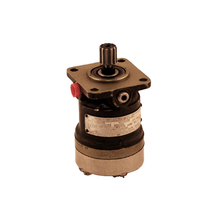
Another type of axial piston pump, sometimes referred to as an in-line pump, is commonly referred to as a Stratopower pump. This pump is available in either the fixed-displacement type or the variable-displacement type.
Two major functions are performed by the internal parts of the fixed-displacement Stratopower pump. These functions are mechanical drive and fluid displacement.
The mechanical drive mechanism is shown in Figure 4-24. In this type of pump, the pistons and block do not rotate. Piston motion is caused by rotating the drive cam, displacing each piston the full height of the drive cam during each revolution of the shaft. The ends of the pistons are attached to a wobble plate supported by a freed center pivot and are held in constant contact with the cam face. As the high side of the rotating drive cam depresses one side of the wobble plate, the other side of the wobble plate is withdrawn an equal amount, moving the pistons with it. The two creep plates are provided to decrease wear on the revolving cam.
The internal features of the variable-displacement Stratopower pump are illustrated in Figure 4-26. This pump operates similarly to the fixed-displacement Stratopower pump; however, this pump provides the additional function of automatically varying the volume output.
This function is controlled by the pressure in the hydraulic system. For example, a pump rated at 3,000 psi provides flow to a 3,000 psi system. As system pressure approaches 2,850 psi, the pump begins to unload (delivering less flow to the system) and is fully unloaded (zero flow) at 3,000 psi.
The bypass system is provided to supply self-lubrication, particularly when the pump is in nonflow operation. The ring of bypass holes in the pistons are aligned with the bypass passage each time a piston reaches the very end of its forward travel. This pumps a small quantity of fluid out of the bypass passage back to the supply reservoir and provides a constant change of fluid in the pump. The bypass is designed to pump against a considerable back pressure for use with pressurized reservoirs.
Eductors (Figure 4-27) are designed to pump large volumes of water. In modern ships, eductors have replaced fire and bilge pumps as a primary means for pumping bilges, deballasting, and dewatering compartments. Eductors allow centrifugal fire pumps to serve indirectly as drainage pumps without the risk of becoming fouled with debris from the bilges. The centrifugal pumps pressurize the fire main, and water from the fire main is used to actuate the eductors. The eductors in modern combat ships have a much larger pumping capacity than fire and bilge pumps. They are installed as part of the piping in the drainage system and are flanged to permit easy removal and disassembly when repairs are necessary.
PDH Classroom offers a continuing education course based on this hydraulic pumps reference page. This course can be used to fulfill PDH credit requirements for maintaining your PE license.

Hydraulic is a complete non-stimulant pre-workout that was formulated specifically by Seth Feroce to increase pumps, performance, muscular endurance focus, strength, and power. Throughout his bodybuilding career, Seth discovered that the more blood and nutrients you can push into the muscle, the more growth you"ll achieve! So he designed a pre-workout to do just that!
Hydraulic uses a combination of L-citrulline, HydroMax® glycerol, AgmaMax™, and Nitrosigine® to increase the diameter of your blood vessels, which allows for more blood, nutrients, and oxygen to be delivered to the working muscles! But we didn"t stop there! Hydraulic also contains several performance boosting ingredients, including Creatine MagnaPower®, Beta-Alanine, Taurine, and B-Vitamins! Lastly, a combination of L-tyrosine and N-acetyl-L-tyrosine will provide you with laser focus.

AN4102-1 PUMP - 700 G.P.H. POWER DRIVEN FUELPART NUMBER: AN4102-1AIRCRAFT: VariousCONDITION: Overhauled - FAA 8130 Airworthiness Cert.DETAILS: 700 GPM engine driven fuel pump

Hydraulic pumps are mechanisms in hydraulic systems that move hydraulic fluid from point to point initiating the production of hydraulic power. Hydraulic pumps are sometimes incorrectly referred to as “hydrolic” pumps.
They are an important device overall in the hydraulics field, a special kind of power transmission which controls the energy which moving fluids transmit while under pressure and change into mechanical energy. Other kinds of pumps utilized to transmit hydraulic fluids could also be referred to as hydraulic pumps. There is a wide range of contexts in which hydraulic systems are applied, hence they are very important in many commercial, industrial, and consumer utilities.
“Power transmission” alludes to the complete procedure of technologically changing energy into a beneficial form for practical applications. Mechanical power, electrical power, and fluid power are the three major branches that make up the power transmission field. Fluid power covers the usage of moving gas and moving fluids for the transmission of power. Hydraulics are then considered as a sub category of fluid power that focuses on fluid use in opposition to gas use. The other fluid power field is known as pneumatics and it’s focused on the storage and release of energy with compressed gas.
"Pascal"s Law" applies to confined liquids. Thus, in order for liquids to act hydraulically, they must be contained within a system. A hydraulic power pack or hydraulic power unit is a confined mechanical system that utilizes liquid hydraulically. Despite the fact that specific operating systems vary, all hydraulic power units share the same basic components. A reservoir, valves, a piping/tubing system, a pump, and actuators are examples of these components. Similarly, despite their versatility and adaptability, these mechanisms work together in related operating processes at the heart of all hydraulic power packs.
The hydraulic reservoir"s function is to hold a volume of liquid, transfer heat from the system, permit solid pollutants to settle, and aid in releasing moisture and air from the liquid.
Mechanical energy is changed to hydraulic energy by the hydraulic pump. This is accomplished through the movement of liquid, which serves as the transmission medium. All hydraulic pumps operate on the same basic principle of dispensing fluid volume against a resistive load or pressure.
Hydraulic valves are utilized to start, stop, and direct liquid flow in a system. Hydraulic valves are made of spools or poppets and can be actuated hydraulically, pneumatically, manually, electrically, or mechanically.
The end result of Pascal"s law is hydraulic actuators. This is the point at which hydraulic energy is transformed back to mechanical energy. This can be accomplished by using a hydraulic cylinder to transform hydraulic energy into linear movement and work or a hydraulic motor to transform hydraulic energy into rotational motion and work. Hydraulic motors and hydraulic cylinders, like hydraulic pumps, have various subtypes, each meant for specific design use.
The essence of hydraulics can be found in a fundamental physical fact: fluids are incompressible. (As a result, fluids more closely resemble solids than compressible gasses) The incompressible essence of fluid allows it to transfer force and speed very efficiently. This fact is summed up by a variant of "Pascal"s Principle," which states that virtually all pressure enforced on any part of a fluid is transferred to every other part of the fluid. This scientific principle states, in other words, that pressure applied to a fluid transmits equally in all directions.
Furthermore, the force transferred through a fluid has the ability to multiply as it moves. In a slightly more abstract sense, because fluids are incompressible, pressurized fluids should keep a consistent pressure just as they move. Pressure is defined mathematically as a force acting per particular area unit (P = F/A). A simplified version of this equation shows that force is the product of area and pressure (F = P x A). Thus, by varying the size or area of various parts inside a hydraulic system, the force acting inside the pump can be adjusted accordingly (to either greater or lesser). The need for pressure to remain constant is what causes force and area to mirror each other (on the basis of either shrinking or growing). A hydraulic system with a piston five times larger than a second piston can demonstrate this force-area relationship. When a force (e.g., 50lbs) is exerted on the smaller piston, it is multiplied by five (e.g., 250 lbs) and transmitted to the larger piston via the hydraulic system.
Hydraulics is built on fluids’ chemical properties and the physical relationship between pressure, area, and force. Overall, hydraulic applications allow human operators to generate and exert immense mechanical force with little to no physical effort. Within hydraulic systems, both oil and water are used to transmit power. The use of oil, on the other hand, is far more common, owing in part to its extremely incompressible nature.
Pressure relief valves prevent excess pressure by regulating the actuators’ output and redirecting liquid back to the reservoir when necessary. Directional control valves are used to change the size and direction of hydraulic fluid flow.
While hydraulic power transmission is remarkably useful in a wide range of professional applications, relying solely on one type of power transmission is generally unwise. On the contrary, the most efficient strategy is to combine a wide range of power transmissions (pneumatic, hydraulic, mechanical, and electrical). As a result, hydraulic systems must be carefully embedded into an overall power transmission strategy for the specific commercial application. It is necessary to invest in locating trustworthy and skilled hydraulic manufacturers/suppliers who can aid in the development and implementation of an overall hydraulic strategy.
The intended use of a hydraulic pump must be considered when selecting a specific type. This is significant because some pumps may only perform one function, whereas others allow for greater flexibility.
The pump"s material composition must also be considered in the application context. The cylinders, pistons, and gears are frequently made of long-lasting materials like aluminum, stainless steel, or steel that can withstand the continuous wear of repeated pumping. The materials must be able to withstand not only the process but also the hydraulic fluids. Composite fluids frequently contain oils, polyalkylene glycols, esters, butanol, and corrosion inhibitors (though water is used in some instances). The operating temperature, flash point, and viscosity of these fluids differ.
In addition to material, manufacturers must compare hydraulic pump operating specifications to make sure that intended utilization does not exceed pump abilities. The many variables in hydraulic pump functionality include maximum operating pressure, continuous operating pressure, horsepower, operating speed, power source, pump weight, and maximum fluid flow. Standard measurements like length, rod extension, and diameter should be compared as well. Because hydraulic pumps are used in lifts, cranes, motors, and other heavy machinery, they must meet strict operating specifications.
It is critical to recall that the overall power generated by any hydraulic drive system is influenced by various inefficiencies that must be considered in order to get the most out of the system. The presence of air bubbles within a hydraulic drive, for example, is known for changing the direction of the energy flow inside the system (since energy is wasted on the way to the actuators on bubble compression). Using a hydraulic drive system requires identifying shortfalls and selecting the best parts to mitigate their effects. A hydraulic pump is the "generator" side of a hydraulic system that initiates the hydraulic procedure (as opposed to the "actuator" side that completes the hydraulic procedure). Regardless of disparities, all hydraulic pumps are responsible for displacing liquid volume and transporting it to the actuator(s) from the reservoir via the tubing system. Some form of internal combustion system typically powers pumps.
While the operation of hydraulic pumps is normally the same, these mechanisms can be split into basic categories. There are two types of hydraulic pumps to consider: gear pumps and piston pumps. Radial and axial piston pumps are types of piston pumps. Axial pumps produce linear motion, whereas radial pumps can produce rotary motion. The gear pump category is further subdivided into external gear pumps and internal gear pumps.
Each type of hydraulic pump, regardless of piston or gear, is either double-action or single-action. Single-action pumps can only pull, push, or lift in one direction, while double-action pumps can pull, push, or lift in multiple directions.
Vane pumps are positive displacement pumps that maintain a constant flow rate under varying pressures. It is a pump that self-primes. It is referred to as a "vane pump" because the effect of the vane pressurizes the liquid.
This pump has a variable number of vanes mounted onto a rotor that rotates within the cavity. These vanes may be variable in length and tensioned to maintain contact with the wall while the pump draws power. The pump also features a pressure relief valve, which prevents pressure rise inside the pump from damaging it.
Internal gear pumps and external gear pumps are the two main types of hydraulic gear pumps. Pumps with external gears have two spur gears, the spurs of which are all externally arranged. Internal gear pumps also feature two spur gears, and the spurs of both gears are internally arranged, with one gear spinning around inside the other.
Both types of gear pumps deliver a consistent amount of liquid with each spinning of the gears. Hydraulic gear pumps are popular due to their versatility, effectiveness, and fairly simple design. Furthermore, because they are obtainable in a variety of configurations, they can be used in a wide range of consumer, industrial, and commercial product contexts.
Hydraulic ram pumps are cyclic machines that use water power, also referred to as hydropower, to transport water to a higher level than its original source. This hydraulic pump type is powered solely by the momentum of moving or falling water.
Ram pumps are a common type of hydraulic pump, especially among other types of hydraulic water pumps. Hydraulic ram pumps are utilized to move the water in the waste management, agricultural, sewage, plumbing, manufacturing, and engineering industries, though only about ten percent of the water utilized to run the pump gets to the planned end point.
Despite this disadvantage, using hydropower instead of an external energy source to power this kind of pump makes it a prominent choice in developing countries where the availability of the fuel and electricity required to energize motorized pumps is limited. The use of hydropower also reduces energy consumption for industrial factories and plants significantly. Having only two moving parts is another advantage of the hydraulic ram, making installation fairly simple in areas with free falling or flowing water. The water amount and the rate at which it falls have an important effect on the pump"s success. It is critical to keep this in mind when choosing a location for a pump and a water source. Length, size, diameter, minimum and maximum flow rates, and speed of operation are all important factors to consider.
Hydraulic water pumps are machines that move water from one location to another. Because water pumps are used in so many different applications, there are numerous hydraulic water pump variations.
Water pumps are useful in a variety of situations. Hydraulic pumps can be used to direct water where it is needed in industry, where water is often an ingredient in an industrial process or product. Water pumps are essential in supplying water to people in homes, particularly in rural residences that are not linked to a large sewage circuit. Water pumps are required in commercial settings to transport water to the upper floors of high rise buildings. Hydraulic water pumps in all of these situations could be powered by fuel, electricity, or even by hand, as is the situation with hydraulic hand pumps.
Water pumps in developed economies are typically automated and powered by electricity. Alternative pumping tools are frequently used in developing economies where dependable and cost effective sources of electricity and fuel are scarce. Hydraulic ram pumps, for example, can deliver water to remote locations without the use of electricity or fuel. These pumps rely solely on a moving stream of water’s force and a properly configured number of valves, tubes, and compression chambers.
Electric hydraulic pumps are hydraulic liquid transmission machines that use electricity to operate. They are frequently used to transfer hydraulic liquid from a reservoir to an actuator, like a hydraulic cylinder. These actuation mechanisms are an essential component of a wide range of hydraulic machinery.
There are several different types of hydraulic pumps, but the defining feature of each type is the use of pressurized fluids to accomplish a job. The natural characteristics of water, for example, are harnessed in the particular instance of hydraulic water pumps to transport water from one location to another. Hydraulic gear pumps and hydraulic piston pumps work in the same way to help actuate the motion of a piston in a mechanical system.
Despite the fact that there are numerous varieties of each of these pump mechanisms, all of them are powered by electricity. In such instances, an electric current flows through the motor, which turns impellers or other devices inside the pump system to create pressure differences; these differential pressure levels enable fluids to flow through the pump. Pump systems of this type can be utilized to direct hydraulic liquid to industrial machines such as commercial equipment like elevators or excavators.
Hydraulic hand pumps are fluid transmission machines that utilize the mechanical force generated by a manually operated actuator. A manually operated actuator could be a lever, a toggle, a handle, or any of a variety of other parts. Hydraulic hand pumps are utilized for hydraulic fluid distribution, water pumping, and various other applications.
Hydraulic hand pumps may be utilized for a variety of tasks, including hydraulic liquid direction to circuits in helicopters and other aircraft, instrument calibration, and piston actuation in hydraulic cylinders. Hydraulic hand pumps of this type use manual power to put hydraulic fluids under pressure. They can be utilized to test the pressure in a variety of devices such as hoses, pipes, valves, sprinklers, and heat exchangers systems. Hand pumps are extraordinarily simple to use.
Each hydraulic hand pump has a lever or other actuation handle linked to the pump that, when pulled and pushed, causes the hydraulic liquid in the pump"s system to be depressurized or pressurized. This action, in the instance of a hydraulic machine, provides power to the devices to which the pump is attached. The actuation of a water pump causes the liquid to be pulled from its source and transferred to another location. Hydraulic hand pumps will remain relevant as long as hydraulics are used in the commerce industry, owing to their simplicity and easy usage.
12V hydraulic pumps are hydraulic power devices that operate on 12 volts DC supplied by a battery or motor. These are specially designed processes that, like all hydraulic pumps, are applied in commercial, industrial, and consumer places to convert kinetic energy into beneficial mechanical energy through pressurized viscous liquids. This converted energy is put to use in a variety of industries.
Hydraulic pumps are commonly used to pull, push, and lift heavy loads in motorized and vehicle machines. Hydraulic water pumps may also be powered by 12V batteries and are used to move water out of or into the desired location. These electric hydraulic pumps are common since they run on small batteries, allowing for ease of portability. Such portability is sometimes required in waste removal systems and vehiclies. In addition to portable and compact models, options include variable amp hour productions, rechargeable battery pumps, and variable weights.
While non rechargeable alkaline 12V hydraulic pumps are used, rechargeable ones are much more common because they enable a continuous flow. More considerations include minimum discharge flow, maximum discharge pressure, discharge size, and inlet size. As 12V batteries are able to pump up to 150 feet from the ground, it is imperative to choose the right pump for a given use.
Air hydraulic pumps are hydraulic power devices that use compressed air to stimulate a pump mechanism, generating useful energy from a pressurized liquid. These devices are also known as pneumatic hydraulic pumps and are applied in a variety of industries to assist in the lifting of heavy loads and transportation of materials with minimal initial force.
Air pumps, like all hydraulic pumps, begin with the same components. The hydraulic liquids, which are typically oil or water-based composites, require the use of a reservoir. The fluid is moved from the storage tank to the hydraulic cylinder via hoses or tubes connected to this reservoir. The hydraulic cylinder houses a piston system and two valves. A hydraulic fluid intake valve allows hydraulic liquid to enter and then traps it by closing. The discharge valve is the point at which the high pressure fluid stream is released. Air hydraulic pumps have a linked air cylinder in addition to the hydraulic cylinder enclosing one end of the piston.
The protruding end of the piston is acted upon by a compressed air compressor or air in the cylinder. When the air cylinder is empty, a spring system in the hydraulic cylinder pushes the piston out. This makes a vacuum, which sucks fluid from the reservoir into the hydraulic cylinder. When the air compressor is under pressure, it engages the piston and pushes it deeper into the hydraulic cylinder and compresses the liquids. This pumping action is repeated until the hydraulic cylinder pressure is high enough to forcibly push fluid out through the discharge check valve. In some instances, this is connected to a nozzle and hoses, with the important part being the pressurized stream. Other uses apply the energy of this stream to pull, lift, and push heavy loads.
Hydraulic piston pumps transfer hydraulic liquids through a cylinder using plunger-like equipment to successfully raise the pressure for a machine, enabling it to pull, lift, and push heavy loads. This type of hydraulic pump is the power source for heavy-duty machines like excavators, backhoes, loaders, diggers, and cranes. Piston pumps are used in a variety of industries, including automotive, aeronautics, power generation, military, marine, and manufacturing, to mention a few.
Hydraulic piston pumps are common due to their capability to enhance energy usage productivity. A hydraulic hand pump energized by a hand or foot pedal can convert a force of 4.5 pounds into a load-moving force of 100 pounds. Electric hydraulic pumps can attain pressure reaching 4,000 PSI. Because capacities vary so much, the desired usage pump must be carefully considered. Several other factors must also be considered. Standard and custom configurations of operating speeds, task-specific power sources, pump weights, and maximum fluid flows are widely available. Measurements such as rod extension length, diameter, width, and height should also be considered, particularly when a hydraulic piston pump is to be installed in place of a current hydraulic piston pump.
Hydraulic clutch pumps are mechanisms that include a clutch assembly and a pump that enables the user to apply the necessary pressure to disengage or engage the clutch mechanism. Hydraulic clutches are crafted to either link two shafts and lock them together to rotate at the same speed or detach the shafts and allow them to rotate at different speeds as needed to decelerate or shift gears.
Hydraulic pumps change hydraulic energy to mechanical energy. Hydraulic pumps are particularly designed machines utilized in commercial, industrial, and residential areas to generate useful energy from different viscous liquids pressurization. Hydraulic pumps are exceptionally simple yet effective machines for moving fluids. "Hydraulic" is actually often misspelled as "Hydralic". Hydraulic pumps depend on the energy provided by hydraulic cylinders to power different machines and mechanisms.
There are several different types of hydraulic pumps, and all hydraulic pumps can be split into two primary categories. The first category includes hydraulic pumps that function without the assistance of auxiliary power sources such as electric motors and gas. These hydraulic pump types can use the kinetic energy of a fluid to transfer it from one location to another. These pumps are commonly called ram pumps. Hydraulic hand pumps are never regarded as ram pumps, despite the fact that their operating principles are similar.
The construction, excavation, automotive manufacturing, agriculture, manufacturing, and defense contracting industries are just a few examples of operations that apply hydraulics power in normal, daily procedures. Since hydraulics usage is so prevalent, hydraulic pumps are unsurprisingly used in a wide range of machines and industries. Pumps serve the same basic function in all contexts where hydraulic machinery is used: they transport hydraulic fluid from one location to another in order to generate hydraulic energy and pressure (together with the actuators).
Elevators, automotive brakes, automotive lifts, cranes, airplane flaps, shock absorbers, log splitters, motorboat steering systems, garage jacks and other products use hydraulic pumps. The most common application of hydraulic pumps in construction sites is in big hydraulic machines and different types of "off-highway" equipment such as excavators, dumpers, diggers, and so on. Hydraulic systems are used in other settings, such as offshore work areas and factories, to power heavy machinery, cut and bend material, move heavy equipment, and so on.
Fluid’s incompressible nature in hydraulic systems allows an operator to make and apply mechanical power in an effective and efficient way. Practically all force created in a hydraulic system is applied to the intended target.
Because of the relationship between area, pressure, and force (F = P x A), modifying the force of a hydraulic system is as simple as changing the size of its components.
Hydraulic systems can transfer energy on an equal level with many mechanical and electrical systems while being significantly simpler in general. A hydraulic system, for example, can easily generate linear motion. On the contrary, most electrical and mechanical power systems need an intermediate mechanical step to convert rotational motion to linear motion.
Hydraulic systems are typically smaller than their mechanical and electrical counterparts while producing equivalents amounts of power, providing the benefit of saving physical space.
Hydraulic systems can be used in a wide range of physical settings due to their basic design (a pump attached to actuators via some kind of piping system). Hydraulic systems could also be utilized in environments where electrical systems would be impractical (for example underwater).
By removing electrical safety hazards, using hydraulic systems instead of electrical power transmission improves relative safety (for example explosions, electric shock).
The amount of power that hydraulic pumps can generate is a significant, distinct advantage. In certain cases, a hydraulic pump could generate ten times the power of an electrical counterpart. Some hydraulic pumps (for example, piston pumps) cost more than the ordinary hydraulic component. These drawbacks, however, can be mitigated by the pump"s power and efficiency. Despite their relatively high cost, piston pumps are treasured for their strength and capability to transmit very viscous fluids.
Handling hydraulic liquids is messy, and repairing leaks in a hydraulic pump can be difficult. Hydrauli


 8613371530291