
stratopower hydraulic pump brands
Quality Aircraft Accessories stocks a wide variety of Stratopower hydraulic pumps. Browse our selection of Stratopower hydraulic pumps below. If you can’t find the Stratopower hydraulic pump you need, contact us with your Stratopower hydraulic pump request.

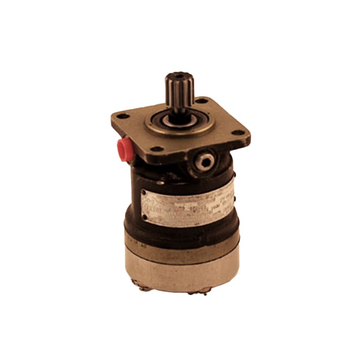
Manufacturer: Vickers Description: Power Driven Hydraulic Pump Variable Delivery Part Number: 65WE01030-3-6 Serial Number: A3-233-D3 Condition: Item appears to be in overall good condition with some...

1941 – New York Air Brake Company acquires Hydraulic Controls (Hycon) of Chicago. Hycon was producing hydraulic steering equipment for ‘M’ series tanks. (Pardee was the inventor). First piston check valve pump designed and built following purchase of company. Pump to be used for propeller blade feathering.
1943 – Hycon moved to Watertown. Stratopower product line of hydraulic equipment for aircraft use started with the first major product being the pump for the twin-boom P-38 ‘Lightning’, built by Lockheed. This was the first variable delivery axial piston pump.
1940-1945 (WWII) – Company employed 3000 in support of war effort. Rapid development of aircraft required corresponding improvements in hydraulics during this period. Need for more hydraulic power dictated increase in pressure levels (1500– 3000 psi) and more efficient systems (variable vs. fixed displacement pumps).
Mid 1950’s – Company produced up to 2000 pumps per month in support of the Korean conflict effort and expanding commercial market. Rotating cylinder block axial piston pumps (valve plate pumps) developed at this time to complement the check valve pump. The new design made possible the manufacture of hydraulic motors and starters, greatly expanding the capabilities and market for the company.
1958 – Development of larger size hydraulic units incorporating the valve plate design for the industrial market undertaken. These units, utilizing technology from the smaller Stratopower aircraft designs, were the start of the Dynapower product line of heavy industry equipment.
1958 – The Dynapower units offered industry the first closed loop hydraulic transmissions. The concept, which consisted of a fixed displacement motor and variable displacement pump with selection of control features, gave users a highly controllable drive train unavailable until now.
1980’s – Dynapower/Stratopower established as wholly separate company of General Signal but sharing the same facilities as New York Air Brake Company.

AN4102-1 PUMP - 700 G.P.H. POWER DRIVEN FUELPART NUMBER: AN4102-1AIRCRAFT: VariousCONDITION: Overhauled - FAA 8130 Airworthiness Cert.DETAILS: 700 GPM engine driven fuel pump

Since 1935, Muncie® Power Products has been a leading source of mobile power components to the truck equipment industry. In addition to Power Take-Offs and hydraulic motors, Muncie offers directional, pressure and flow control valves as well as system design capabilities. Call us today or visit our website for more information.
FluiDyne is an ISO certified manufacturer of hydraulic pumps, motors & valves. Our promise is to serve and respect the rebuilders and resellers of North America and the global market with high quality new and remanufactured pumps, motors, valves, filters and filter elements.
Having innovative solutions for mission-critical applications makes Hydraulics Technology the preferred. For over 25 years, our impressive list of hydraulic pumps has met the needs of various applications. In assuring the highest quality products to our customers and meeting their expectations, Hydraulics Technology maintains ISO Certification. HTI is ISO 9001:2008 Certified.
Industrial Flow Solutions is a trusted manufacturer of hydraulic pumps and centrifugal pumps. We pride ourselves on our high-quality products and personalized customer service. Various industries we serve include industrial, food & beverage, and medical. All of our products are tested to ensure quality and durability.
AeroControlex began manufacturing pumps in Cleveland, Ohio in 1945. Over the years, AeroControlex has established itself as an industry leader in the production of hydraulic, fuel, lube and scavenge, centrifugal and coolant pumps. Our worldwide customer base demands the highest quality, cost effective products for the most demanding commercial and military applications.
All World Machinery Supply offers high-quality, affordable pumps, motors, and power units from reputable brands like Daikin, Nachi, Eaton, Tokimec, NOP, Grundfos, Yuken, and Fuji . Our team of representatives and engineers can find or cross any pump/mortor to what you are looking for. We can even help you design a custom application suited to your fit your needs.
American Eagle Accessories Group is a manufacturer of truck equipment accessories. These products include: hydraulic-driven air compressors, drawer systems (tool storage), bolt bins (fastener and fitting storage), lube skids, lube trailers, fuel trailers, and utility construction trailers. All of our products are designed and manufactured in the U.S.A.
Founded in 1991, AZ Hydraulic Engineering manufactures high quality air-operated hydraulic pumps serving a broad clientele. We offer hydraulic piston pumps, power units, tank pumps and more with 25 different pressure ranges up to 50,000PSI and a proven track record for reliability and easy, low cost maintenance. AZ Hydraulics is the source for quality hydraulic pumps and friendly customer service.
Barbee Engineered Testing Systems is a manufacturer of hydraulic power units, hydraulic valve testers, air-driven hydraulic piston pumps, high pressure pumps, hydraulic power systems, high pressure systems and more. Our hydraulic pumps are available with up to 30,000 PSI. Check out our website.
Berendsen Fluid Power is one of the largest distributors of pneumatic and hydraulic products in North America. We distribute from quality manufacturers products such as hydraulic pumps, hydraulic motors, hydraulic gear pumps, mixer pumps and more. Visit our website for more information.
Bosch Rexroth is a global leader in manufacturing industrial hydraulics, including proportional and servo valves. Directional control, high response, flow control, pressure relief, pressure reducing, and servo valves name some of our products. Our rugged valves are a perfect fit your electrohydraulic control applications. A variety of models are available for your viewing on our website.
Brand Hydraulics is a leading designer and manufacturer of high-quality hydraulic valves including hydraulic directional control valves, hydraulic flow control valves, hydraulic relief valves, hydraulic selector valves, shuttle valves, pilot check valves, flow dividers and more. Brand also has a line of quality hand-operated hydraulic pumps. Premium hydraulics since 1956.
For 40 years, Bucher Hydraulics, Inc. has specialized in hydraulic systems, including products such as hydraulic motors and hydraulic power units. Applications include concrete pumps, forage wagons, harvesters, lifting devices, recycling machines, door openers, log splitters and many others.
A Cascon hydraulic pump is used in a wide range of OEM equipment market applications. Whether you"re in the aircraft & aerospace, chemical, gas turbine or industrial or mobile markets, our hydraulic pumps and specialty pumps will meet your requirements and provide solutions that an off-the-shelf pump cannot. Contact Cascon, Inc. today for more information!
CAT PUMPS specializes in high pressure pumps, reciprocating pumps, positive displacement pumps, plunger-piston pumps and we also manufacture hydraulic pumps and hydraulic power units. We are an industry-leader in customer service and quality triplex pump design and products.
CLYDEUNION Pumps is one of the world"s leading pump companies - a centre of excellence in Pump Technology, Hydraulic Design and Engineering. We are structured to provide a specific focus on each of our customer"s key markets as well as providing full global aftermarket support. CLYDEUNION Pumps incorporates an accumulation of over 300 years of engineering expertise.
We have over 55 years of experience in manufacturing hydraulic components. CROSS Manufacturing, Inc. distributes hydraulic filters, hydraulic cylinders, hydraulic gear pumps and hydraulic systems worldwide. Our hydraulic systems are used for automotive, agricultural, mining and construction purposes.
D&D Machine & Hydraulics Inc, located in Fort Myers, Florida, is a manufacturer of hydraulically driven, submersible pumping systems that serves the Agricultural, Construction, Industrial, Mining, Petroleum and Municipal markets worldwide. More than 45 years ago, D&D realized the unlimited potential of hydraulics. Since then, D&D has revolutionized the dewatering industry with a series of hydraulically driven pumps that provide the most technologically advanced and precisely engineered features available today. Specifically, D&D builds electric or diesel-driven Power Units and Axial Flow, Trash, Sludge, Slurry/Digester and Mixed Flow pump heads. The flow capacity of these pump heads range from 450gpm to 55,000gpm and heads of 250 feet are attainable. If a standard pump will not meet the performance needed for a special application, D&D’s wide range of specialty pumps can meet your individual requirement.
When the owners acquired D&D, it was a four-employee, custom machine shop that repaired pumps used by local farmers. Shortly thereafter, D&D began to manufacture hydraulic pumps for a local sales and rental company. In the 1980s, as the business grew, D&D began to sell to other customers throughout the country, eventually achieving global recognition.
Danfoss will drive your vehicle transmission to a new level of performance with our Danfoss piston pumps and motors. Designed for intelligent vehicle management systems, our range brings you closer to your goals for reduced fuel consumption and high operator comfort. We deliver components and systems for machine from 15 to 2500 horsepower.
We create hydraulic pumps that can be utilized for standard and specialized purposes. Our high pressure pumps can handle pressures from 3,000 to 15,000 psi with flows of 200 gpm. Our systems can also perform with various fluids including mineral-oils, low-lubricity fire-resistant fluids. We are dedicated to developing the most reliable hydraulic pumps!
Eaton Hydraulics designs, manufactures and markets a comprehensive line of reliable, efficient hydraulic systems and components including hydraulic motors, hydraulic power units and other hydraulic systems. We serve various markets and applications with our quality systems and accessories.
We offer and repair hydraulic pumps and hydraulic motors. As one of the biggest suppliers of hydraulic power units (original or replacement) and a worldwide distributor, we can ship anywhere in the world immediately. Our inventory of motors is immense and our sales staff has years of experience.
Welcome to the Florida Hydraulic Industrial web site. Browse our categories for hydraulic pumps, hydraulic cylinders, hydraulic and industrial hose, including a wide variety of pressure washer hose, all common hydraulic hose fittings.
Flowserve® is the world leading manufacturer of quality hydraulic pumps — air piston pumps, hydraulic water pumps, vane pumps, entire hydraulic systems, plus valve repair. Our products are used by many industries — chemical; hydrocarbon processing; oil and gas; power; water resources.
Fluid Power International provides expertise in hydraulic pump repair & replacement. We specialize in repairing & replacing metric pumps & motors for Japanese and German heavy machinery as well as hydraulic components for excavators. We will tear down and inspect your part with no obligation.
Established in 1978, Gator Pump manufactures high volume pumps for irrigation, flood control, liquid waste pumping and many other applications. Steel fabricated hydraulic pumps are offered in several different sizes and configurations including vertical pumps, floating pumps and trailer pumps as well as custom pumps operated on electric, diesel or hydraulics to suit clients" needs. Call us today!
We provide a number of different styles of air driven high pressure hydraulic pumps ranging from 100 PSI to 60,000 PSI. Here at High Pressure Technologies, LLC we take customer satisfaction very seriously which is why we can customize our products to match your requirements. It is our goal to exceed your expectations. Please visit our website or give us a call today to learn more information!
We started developing hydraulic drive submersible pumps in 1977. We can provide you with a hydraulic pump, hydraulic gear pump and hydraulic power unit to match. If a standard system doesn"t meet your needs, we can custom design one for you. We make our models in a variety of materials.
Since our beginning in 1947, Hydraulic Supply Company (HSC) has been dedicated to fulfilling customers’ needs. We are a full service distributor of fluid power products and services. We carry a selection of over 20,000 hydraulic, pneumatic and industrial products in stock from the most recognized brands in the industry. Our goal is to provide customers with a large selection of hydraulic, pneumatic and industrial products with the best professional services, right when you need them.
Made-to-order & made-to-last custom hydraulic pumps faster than you can expect from other companies. The widest selection of hydraulic gear pumps & piston pumps, plus stock replacement pumps ready for immediate shipment. Brands: Webster, Danfoss, Barnes, Haldex, Cessna, Eaton, Vickers, etc. Hydraulic.Net’s specialization is in short run special application gear pumps with little tooling expense.
Hydraulics International, Inc. (HII), headquartered in Chatsworth, California, U.S.A., is a leading manufacturer and supplier of integrated products, services and support to military forces, aviation and commercial industries, government agencies and prime contractors worldwide. Focused on defense and commercial technology, HII develops manufactures and supports a broad range of products and systems for over a hundred industries as well as mission critical and military sustainment requirements worldwide. HII is also recognized as a leading manufacturer and supplier of air, electric, hydraulic, & manual driven high-pressure products to Automotive, Airline & Aerospace, Cannabis, CNG, Defense, Fire-Health & Safety, Fluid Power, Fuel Cell Hydrogen, General Manufacturing, Laboratory, University & Research, Mining, Oil & Gas, Paintball, Plastics, Power & Energy, Recreational Sports Diving, Electronics and other industries. We produce 85% of our products internally, thus eliminating our dependency upon outside sources for quality, reliability, and expediency. Because of our self-sufficiency, we are able to maintain key competitive advantages that include faster response to engineering and design problems, and reliability of components critical to functionality.
Here at Hydreco we manufacture hydraulic solutions for a number of markets including: agricultural, municipal, construction, mining and transportation. Our company has an extensive history of engineering success. If you are unsure what hydraulic products are best for your task then just let one of our representatives know your application and we can handle the rest!
Over 50 years, Hydro Leduc has developed more than 100 patents because of our passion for innovation in the hydraulics field. We find solutions to our customers’ most complex and demanding applications for piston pumps, hydraulic motors, hydro-pneumatic accumulators and custom hydraulic components.
HYTORC developed the jet series pumps which are portable, heavy duty, light weight, high flow to withstand harsh environments. These air or electric driven Hydraulic Pumps are engineered for continuous, non-stop use in harsh environments. If used on Torque Tools, Jacks, Cutters, Presses or Bending equipment, their reliability is unmatched by any other Hydraulic Power Pack.
We are a distributor of hydraulic and pneumatic products such as hydraulic pumps, filters, motors, valves and more. Our manufacturers make hydraulic gear pumps, piston pumps and hydraulic pumps with aluminum or cast iron casings. We have been in business for 30 years and service all of our products.
Founded in 1971, Interface Devices is a world-class designer and manufacturer of air driven fluid pumps, hydraulic valves and custom engineered fluid power products. IDI proudly designs and manufactures all our products at our Milford, CT facility. As we continue to grow and develop it is our principle aim to provide quality in our designs and manufacturing while responding to customer needs.
Jones Hydraulic Service is a company dedicated to solving the needs of our customers. Jones Hydraulic Service is a leading supplier / vendor too many large and small corporations, and many independent contractors. Our customer service is a top priority. Whether customers are looking to Purchase, Rent or Repair hydraulic tooling or keep their workers safe with High Visibility Apparel or Mosquito Repellent we get the job done. Jones Hydraulic Service is proud to be serving the energy, marine, petrochemical, railroad, construction, foundation repair, pipeline and shipyard industries since 1977. Jones Hydraulic represents some of the world’s leading Hydraulic Tool & Equipment manufacturers that include SPX Power Team, SafeWay Hydraulics, Pell Hydrashear, TORC LLC, Eagle Pro, and more. Offering Hydraulic Tool & Equipment Sales, Service and Repair for 40 years.
Jones Hydraulic listened to its customers needs for industrial supplies and now stocks LED Work Lights, Safety Mats, Hand Held Power Tools, LED Flood Head Lamp, Spill Clean Up Supplies, Water Dams and more. Jones Hydraulic represents the leading industrial supply companies including PowerSmith, Genesis, Spill Tackle, Quick Dams Nite Ize and more.
Jones Hydraulic helps their customer create a safe and healthy work environment by providing safety products that include Personal Protective Equipment, Hi-Vis Clothing, First Aid Supplies, Mosquito and Insect Repellents, Eye Protection and Outdoor Protective Equipment. Jones Hydraulic represents some of the leading safety product manufacturers such as SAS Safety, GSS Safety, Sawyer, Southern Glove and more.
We recently opened a Safety Equipment & Hydraulic Tool Showroom. We welcome you to stop by and see some of the latest product offerings. Our Showroom is located at 5955 Armour Drive, Houston, TX 77020. We are proud of our 40 year history and look forward to serving our customers for many more years to come.
At Linde Hydraulics, we pride ourselves on our designing/manufacturing of high pressure pumps and the Linde Hydraulic Valve. Our hydraulic pumps have been a mainstay since 1970. Our pumps are used in agriculture and defense. A complete hydraulic system can be offered, along with motors that deliver reliable performance.
Our Maximator® air-driven hydraulic pumps deliver from 60 to 60,000 PSI and cycle automatically. The Maximator® pumps are used in our hydraulic power units. We can provide you with standard or customized high pressure pump power systems. Repair and refurnishing services also available.
Since 1941, Metro Hydraulic Jack Co. has been your single source for all your hydraulic needs. We represent a wide variety of material lift and equipment manufacturers and we sell only the best. Our products are designed to help improve the safety of your work environment and increase your productivity. We are proud to provide a wide selection of high-quality hydraulic lifting products to our customers. As a third-generation family-owned business, all of us at Metro Hydraulic Jack Co. pride ourselves on delivering the same high-quality hydraulic products and top-notch customer service as we have always been. Our knowledgeable sales staff are experts at specifying the right equipment to meet our customers’ requirements and needs. Our extensive list of hydraulic lifting products includes aerial lifts , dock lifts , pallet lifts, platform lifts , rotary lifts, scissor lifts, small hydraulic lifts, and hydraulic lift systems. Additionally, we supply cylinders, pumps, valves, hydraulic and air jacks, pullers, punches, lubrication equipment, and more. The manufacturers we represent, including Autoquip, ECOA, Lift Products, Inc., and Lift-rite, are the best in the industry and we are proud to offer their products.
Our engineering services include custom hydraulic and lube system design to meet our customers’ specifications, as well as other specialized services. We are a supplier to numerous industries, including automotive, construction, industrial, material handling, mobile, and railroad. You can find an impressive list of our customers on our website. Call or email us today to learn how we can service your hydraulic needs.
Our Hydraulics Division, headquartered in Greenwood Indiana, is a world-class manufacturer of pumps, valves, flow controls, hydraulic power units and other products. We are known not only for our product excellence but for our competitive pricing and the ready availability of our products when customers need them.
Sales, service and rental for all major brands of hydraulic pumps and other air, electric and hydraulic equipment. Hydraulic pump offerings include hand pumps, air pumps, electric pumps, gas pumps and intensifiers. Highly skilled at matching tool to application for hydraulic pumps and more.
Oilgear heavy-duty axial piston hydraulic pumps are built. Engineered with Oilgear’s advanced “hard-on-hard” rotating group and hydrodynamic bearing support on the cylinder barrel, our pumps provide longer operational life and optimal resistance to contamination. Available in a variety of frame sizes and control options, Oilgear offers just the right pump to fit your demanding needs.
Founded nearly 25 years ago, Panagon Systems has remained a trusted company producing hydraulic parts on demand for a number of shops, manufacturers and industries. The company, located in Macomb, Michigan, is the largest aftermarket hydraulic piston pump and parts manufacturer in North America, providing a vast variety of current and obsolete components. Panagon has the ability to produce a product from raw materials to a finished pump, assembled, tested, painted and shipped from our facility. Due to the phasing out of old products, customers usually find that the parts they need are no longer available, or that the delivery time is too long or the cost is too high. Panagon Systems attempts to fill the void OEM’s create by manufacturing the phased out, expensive, unavailable pumps, motors and transmissions, from companies like Vickers, Denison and Rexroth.
We manufacture hydraulic pumps, motors and parts for a variety of industrial and mobile applications. Our replacements are equivalent to the Eaton/Vickers line of PVH, PVQ, PVB, PVM, PVE, PFB, MFB, MFE, TA19, TA1919, TDV10 and TDV20 series units and Rexroth A10V series units.
In addition to supplying complete replacement piston pumps, Panagon also offers all replacement parts for all series units such as Rotating Groups, Shafts, Compensators, Yokes, Valve Blocks, Housings, Bearings, Seal Kits, Cylinder Blocks, Shoe Plates, Swash Plates, Piston Kits, Wafer Plates, Control Pistons, Control Rods, Bias Pistons, Bias Rods, Spacer Kits, Saddle Bearings, and more.
Parker"s Hydraulic Pump and Power Systems Division provides a broad selection of piston pumps, hydraulic motors and power units that help our customers meet their industrial and mobile application needs.
The Parker Pump & Motor Division specializes in gear pumps and motors used in a myriad of industries. With decades of experience, PMD provides the best products in the market, supplemented by best-in-class customer service, and the deepest knowledge in the industry.
Perfection Hydraulics manufactures, distributes, and services hydraulic cylinders, hydraulic pumps, hydraulic valves, hydraulic gear pumps, and other hydraulic components for heavy equipment. Our products provide you with the best value available for today’s dynamic industry. With our reputation for quality and reliability, you can rely on us for your heavy duty hydraulics needs.
Pierce Sales is a manufacturer and distributor of 12-volt hydraulic pumps, hydraulic hoses, hydraulic fittings, tie-rod cylinders and many more products. We offer professional installation services. We also have spare parts and provide repair services to get your equipment running as soon as possible.
Precision Fluid Power is a distributor of hydraulic pumps, including hydraulic vane pumps, hydraulic piston pumps and hydraulic gear pumps. We provide new hydraulic motors or we rebuild them, as well as hydraulic valves and hydraulic cylinders. We also offer hydraulic pump repair. Call us today.
Robeck Fluid Power is a leading manufacturer of hydraulic pumps and an assortment of lubrication equipment. Our products include aluminum structural framing, automation equipment, electronics, fluid conveyance equipment, hydraulic pumps, lubrication systems, and pneumatic products. We are a fully authorized distributor of Eaton, Charlynn, Hydro-line, Aeroquip, and Vickers products. Visit our website to learn more about our manufacturers or to speak with a sales representative.
Since 1978, we have been offering hydraulic pumps, motors, valves and cylinders with 100 years combined experience. We distribute hydraulic systems, and also do on-site machine shop repair services and rebuilding. Our quality hydraulic power units can be ordered around the clock for your convenience.
SC Hydraulic Engineering has been a leader in the design & manufacture of various air-powered hydraulic pumps, hydraulic piston pumps, hydraulic power units and systems plus hydraulic valves—relief, inline check, high pressure. We also have the ability to customize our products to fit your needs. In business since 1953, we work worldwide through distributors and manufacturers.
Since 1899, SIMPLEX products have been used by industries that need hydraulic and mechanical equipment and solutions. Our continuous duty hydraulic pumps are equipped for up to 5HP, as are our gas, air & electric hydraulic pumps for heavy-duty tooling applications. Our positioning and lifting products turn challenges into progress.
Established in 1979, Southwest Seal and Supply has grown to become one of the most predominant distributors of sealing, hydraulic hoses, fittings, couplings/connectors, gasketing and fluid control products in the Southwest. We offer a wide range of products including the best in selection, quality, and value-added services.
POWER TEAM is a world leader in hydraulic special service tools and equipment for motor vehicle and industrial markets, manufacturingprecision quality high-pressure hydraulic products, which include pumps,cylinders, valves, clamping components, related hydraulic accessoriesand special tools and equipment.
Stone Hydraulic Systems manufactures AC and DC hydraulic power units for a broad range of OEM applications such as auto hoists, dock levelers, hose crimpers, lift tables and compactors to name a few. Stone"s products provide a wide power range up to 5.5 horsepower.
SRS Crisafulli hydraulic-powered pumps handle industrial-strength pumping jobs: trash, mud, waste, raw sewage, sludge. Discharge sizes 2" to 24" and flows to 18,000 GPM. Standard Power Unit models in electric, diesel or gas, 32 to 180 horsepower, outputs from 18 to 119 GPM or custom built to your spec.
Sunfab was founded by Eric Sundin in the year of 1925. Sunfab develops, produces and sells components to operate hydraulic equipment within the area of mobile vehicles. After more than 90 years, the third generation of the Sundins are still running the company in the spirit of Eric Sundin, with a family atmosphere, flexibility and innovative solutions.
TK Trailer Parts is a dedicated manufacturer of high quality products. We are a turnkey supplier of hydraulic cylinders, hydraulic pumps, hydraulic valves, and much more. If you need assistance with find the right solution for you then feel free to reach out to one of our representatives.
Serving customers worldwide since 1911 with our innovative positive displacement pumping solutions, including custom designs. For even the toughest industrial, OEM & sanitary applications, we manufacture Vane Pumps, Internal & External Gear Pumps & more.
Willman Industries is a large, independent, jobbing foundry, located in Cedar Grove, Wisconsin. We produce all types of gray iron and ductile iron components, ranging from ounces to 40,000 lbs. Thin-walled exhaust manifolds, heavy-section hydraulic pumps, valves, housings, flywheels, clutch plates, machine tools, power generating equipment are typical of our product mix.
Zinko Hydraulic Jack is a leading manufacturer of high-quality hydraulic products. In addition to our namesake hydraulic jacks, we provide scissor jacks and aluminum jacks as well as hydraulic cylinders, lifts and other material handling equipment. At Zinko, your needs are met with a diverse inventory of quality hydraulic pumps including air pumps, hand pumps, electric hydraulic pumps and more.

This page provides the chapter on hydraulic pumps from the U.S. Navy"s fluid power training course, NAVEDTRA 14105A, "Fluid Power," Naval Education and Training Professional Development and Technology Center, July 2015.
Pumps are used for some essential services in the Navy. Pumps supply water to the boilers, draw condensation from the condensers, supply sea water to the firemain, circulate cooling water for coolers and condensers, pump out bilges, transfer fuel, supply water to the distilling plants, and serve many other purposes. Although the pumps discussed in this chapter are used primarily in hydraulic systems, the principles of operation apply as well to the pumps used in other systems.
The purpose of a hydraulic pump is to supply a flow of fluid to a hydraulic system. The pump does not create system pressure, since pressure can be created only by a resistance to the flow. As the pump provides flow, it transmits a force to the fluid. As the fluid flow encounters resistance, this force is changed into a pressure. Resistance to flow is the result of a restriction or obstruction in the path of the flow. This restriction is normally the work accomplished by the hydraulic system, but can also be restrictions of lines, fittings, and valves within the system. Thus, the pressure is controlled by the load imposed on the system or the action of a pressure-regulating device.
A pump must have a continuous supply of fluid available to the inlet port to supply fluid to the system. As the pump forces fluid through the outlet port, a partial vacuum or low-pressure area is created at the inlet port. When the pressure at the inlet port of the pump is lower than the local atmospheric pressure, atmospheric pressure acting on the fluid in the reservoir forces the fluid into the pump"s inlet. If the pump is located at a level lower than the reservoir, the force of gravity supplements atmospheric pressure on the reservoir. Aircraft and missiles that operate at high altitudes are equipped with pressurized hydraulic reservoirs to compensate for low atmospheric pressure encountered at high altitudes.
Pumps are normally rated by their volumetric output and pressure. Volumetric output is the amount of fluid a pump can deliver to its outlet port in a certain period of time at a given speed. Volumetric output is usually expressed in gallons per minute. Since changes in pump speed affect volumetric output, some pumps are rated by their displacement. Pump displacement is the amount of fluid the pump can deliver per cycle. Since most pumps use a rotary drive, displacement is usually expressed in terms of cubic inches per revolution.
As a pump does not create pressure, however, pressure develops by the restrictions in the system affecting the volumetric output of the pump. As the system pressure increases, the volumetric output decreases. This drop in volumetric output is the result of an increase in the amount of internal leakage from the outlet side to the inlet side of the pump. This leakage is referred to as pump slippage and is a factor that must be considered in all pumps. This explains why most pumps are rated in terms of volumetric output at a given pressure.
Many different methods are used to classify pumps. Terms such as positive-displacement, nonpositive-displacement, fixed-displacement, variable-displacement, fixed delivery, variable delivery, constant volume, and others are used to describe pumps. The first two of these terms describe the fundamental division of pumps; that is, all pumps are either positive-displacement or nonpositive-displacement.
Basically, pumps that discharge liquid in a continuous flow are referred to as nonpositive-displacement, and those that discharge volumes separated by a period of no discharge are referred to as positive-displacement.
Positive-displacement pumps capture confined amounts of liquid and transfer it from the suction to the discharge (flow is created and pressure is the result).
The centrifugal pump is a nonpositive-displacement pump which delivers a continuous flow produced by a rotating impeller. Centrifugal pumps are widely used aboard ship for pumping nonviscous liquids. In the engine room you will find several important centrifugal pumps: the feed booster pump, the fire and flushing pump, condensate pumps, auxiliary circulating pumps, and the main feed pump. They have several advantages over reciprocating pumps; they are simpler, more compact, lighter, and easily adapted to a high-speed prime mover. Centrifugal pumps also have disadvantages; they have poor suction lift characteristics and they are sensitive to variations in head and speed.
The centrifugal pump uses the throwing force of a rapidly revolving impeller. The liquid is pulled in at the center or eye of the impeller and is discharged at its outer rim. By the time the liquid reaches the outer rim of the impeller, it has acquired a considerable velocity (kinetic energy). The liquid is then slowed down by being led through a volute or through a series of diffusing passages. As the velocity of the liquid decreases, its pressure increases and thus its kinetic energy is transformed into potential energy.
A centrifugal pump does not provide a positive seal against slippage; therefore, the output of the pump varies as system pressure varies. In other words, the volume of fluid delivered for each cycle depends on the resistance to the flow. This type of pump produces a force on the fluid that is constant for each particular speed of the pump. Resistance in the discharge line produces a force in a direction opposite the direction of the force produced by the pump. When these forces are equal, the fluid is in a state of equilibrium and does not flow.
There are many different types of centrifugal pumps, but the two which are most likely encountered aboard ship are the volute pump and the volute turbine, or diffuser pump.
In the volute pump shown in Figure 4-1, the impeller discharges into a volute. As the liquid passes through the volute (a gradually widening spiral channel in the pump casing) and into the discharge nozzle, a great part of its kinetic energy is converted into potential energy.
In the diffuser pump shown in Figure 4-2, the liquid leaving the impeller is first slowed down by the stationary diffuser vanes which surround the impeller. The liquid is forced through gradually widening passages in the diffuser ring (not shown) and into the volute. Since both the diffuser vanes and the volute reduce the velocity of the liquid, there is an almost complete conversion of kinetic energy to potential energy.
A propeller pump is another type of nonpositive-displacement pump. This pump is used primarily where there is a large volume of liquid with a relatively low total head requirement. This pump is usually limited to where the total head does not exceed 40 to 60 feet.
The chief use of the propeller pump is for the main condenser circulating pump. In most ships this has an emergency suction for pumping out the engine room.
The main condenser circulating pump is of the vertical propeller type. The pump unit consists of three major parts: the propeller, together with its bearings and shaft; the pump casing; and the driving unit, which may be an auxiliary steam turbine or electric motor.
If the discharge valve of a nonpositive-displacement pump is completely shut, the discharge pressure will increase to the maximum for that particular pump at a specific speed. Nothing more will happen except that the pump will churn the fluid and produce heat.
A positive-displacement pump is one in which a definite volume of liquid is delivered for each cycle of pump operation. Positive-displacement pumps use two opposing, rotating elements to displace liquid from the suction side of the pump to the discharge side of the pump. As the elements rotate, the chamber formed between the rotors, housing, and cover collects the liquid on the inlet side of the pump and carries the liquid to the discharge side of the pump. Positive-displacement pumps are used for low flow and high-pressure applications.
Positive-displacement pumps sometimes do not pump the full displacement for which they are rated because of slippage. To allow a positive pump"s rotors to rotate, small clearances must be maintained between the rotors and housing. The liquid that slips by will partially fill the inlet cavity. This amount of liquid must be repumped, preventing the pump from reaching its full rated capacity and decreasing its volumetric efficiency.
Positive-displacement pumps physically displace the fluid; therefore, shutting a valve downstream of a positive-displacement pump will result in a continual buildup in pressure resulting in severe damage to the pipeline or pump.
Positive-displacement pumps are further classified as fixed-displacement or variable-displacement. The fixed-displacement pump delivers the same amount of fluid on each cycle.
The variable-displacement pump is constructed so that the displacement per cycle can be varied. The displacement is varied through the use of an internal controlling device.
Pumps may also be classified according to the specific design used to create the flow of fluid. Practically all hydraulic pumps fall within three design classifications − centrifugal, rotary, and reciprocating. The use of centrifugal pumps in hydraulics is limited and will not be discussed in this text.
All rotary pumps have rotating parts which trap the fluid at the inlet (suction) port and force it through the discharge port into the system. Gears, screws, lobes, and vanes are commonly used to move the fluid. Rotary pumps are positive-displacement of the fixed-displacement type. The rotary pump tree is illustrated in Figure 4-3.
Rotary pumps (Figure 4-4 through Figure 4-7) are designed with very small clearances between rotating parts and stationary parts to minimize slippage from the discharge side back to the suction side. These types of pumps are designed to operate at relatively moderate speeds. Operating at high speeds causes erosion and excessive wear which results in increased clearances.
There are numerous types of rotary pumps and various methods of classification. They may be classified by the shaft position — either vertically or horizontally mounted; the type of drive — electric motor, gasoline engine, and so forth; their manufacturer"s name; or their service application. However, classification of rotary pumps is generally made according to the type of rotating element. A few of the most common types of rotary pumps are discussed in the following paragraphs.
Internal gear pumps deliver fluid between the gear teeth from the inlet to outlet ports. The outer gear (rotor) drives the inner or idler gear on a stationary pin. The gears create voids as they come out of mesh and fluid flows into the cavities. As the gears come back into mesh, the volume is reduced and the liquid is forced out of the discharge port. The crescent prevents liquid from flowing backwards from the outlet to the inlet port. Internal gear pumps may be either centered or off-centered. Internal gear pumps may be further divided into those with a crescent and those with no crescent.
This pump is illustrated in Figure 4-8. The drive gear is attached directly to the drive shaft of the pump and is placed off-center in relation to the internal gear. The two gears mesh on one side of the pump, between the suction (inlet) and discharge ports. On the opposite side of the chamber, a crescent-shaped form fitted to a close tolerance fills the space between the two gears.
The rotation of the center gear by the drive shaft causes the outside gear to rotate, since the two are meshed. Everything in the chamber rotates except the crescent. This rotation causes liquid to be trapped in the gear spaces as they pass the crescent. The liquid is carried from the suction port to the discharge port where it is forced out of the pump by the meshing of the gears. The size of the crescent that separates the internal and external gears determines the volume delivery of the pump. A small crescent allows more volume of liquid per revolution than a larger crescent.
In contrast to the internal gear pump with a crescent, the internal gear pump without crescent consists of a gear within a gear. This pump consists of a pair of gear-shaped elements — one within the other — located in the pump chamber. The inner gear is connected to the drive shaft of the power source.
The operation of this type of internal gear pump is illustrated in Figure 4-9. The tooth design of each gear is related to that of the other in such a way that each tooth of the inner gear is always in sliding contact with the surface of the outer gear. Each tooth of the inner gear meshes with the outer gear at just one point during each revolution. As the gears continue to rotate in a clockwise direction, the inner gear teeth approach and mesh with the outer gear teeth. Note that the inner gear has one less tooth than the outer gear. As a result, the outer gear rotates at just six-sevenths the speed of the inner gear. For example, if the inner gear rotates at 1,400 revolutions per minute (rpm), the outer gear rotates at 1,200 rpm.
At one side of the point of mesh, pockets of increasing size are formed as the gears rotate; simultaneously, the pockets decrease in size on the other side. The pockets on the right-hand side of the drawings increase in size as you move down the illustration, while those on the left-hand side decrease in size. The motion of the gears draws fluid in on one side of the pump and pushes it out of the other side.
The operation of this type of internal gear pump is illustrated in Figure 4-10. To simplify the explanation, the teeth of the inner gear and the spaces between the teeth of the outer gear are numbered. Note that the inner gear has one less tooth than the outer gear. The tooth form of each gear is related to that of the other in such a way that each tooth of the inner gear is always in sliding contact with the surface of the outer gear. Each tooth of the inner gear meshes with the outer gear at just one point during each revolution. In the illustration, this point is at the X. In view A, tooth 1 of the inner gear is meshed with space 1 of the outer gear. As the gears continue to rotate in a clockwise direction and the teeth approach point X, tooth 6 of the inner gear will mesh with space 7 of the outer gear, tooth 5 with space 6, and so on. During this revolution, tooth 1 will mesh with space 2; and during the following revolution, tooth 1 will mesh with space 3. As a result, the outer gear will rotate at just six-sevenths the speed of the inner gear.
At one side of the point of mesh, pockets of increasing size are formed as the gears rotate, while on the other side the pockets decrease in size. In Figure 4-10, the pockets on the right-hand side of the drawings are increasing in size toward the bottom of the illustration, while those on the left-hand side are decreasing in size toward the top of the illustration. The intake side of the pump would therefore be on the right and the discharge side on the left.
External gear pumps (Figure 4-11) are similar to internal gear pumps in that two gears come into and out of mesh to produce flow. In the external gear pump, one gear (drive gear) is driven by a motor and in turn drives the other gear (driven gear). As the gears mesh, the fluid, which is trapped in the gear teeth spaces between the housing and the outside of the gears, are transferred from the suction side of the pump to the discharge side. As the gears come out of mesh, they create expanding volume on the inlet side of the pump.
Because the gears are supported on both sides, external gear pumps are quiet-running and are routinely used for high-pressure applications such as hydraulic applications. With no overhung bearing loads, the rotor shaft can"t deflect and cause premature wear.
The spur gear pump (Figure 4-12) consists of two meshed gears which revolve in a housing. The drive gear in the illustration is turned by a drive shaft which is attached to the power source. The clearances between the gear teeth as they mesh and the pump housing are very small.
The herringbone gear pump (Figure 4-13) is a modification of the spur gear pump. A herringbone gear is composed of two helixes spiraling in different directions from the center of the gear. The liquid is pumped in the same manner as in the spur gear pump; however, the herringbone pump has two sets of teeth (double helical) set in a V-shape. Each set of teeth begins its fluid discharge phase before the previous set of teeth has completed its discharge phase. This overlapping of teeth and the relatively larger space at the center of the gears tend to minimize pulsations and give a steadier flow than the spur gear pump.
The helical gear pump (Figure 4-14) is another type of rotary pump. A helix is the curve produced when a straight line moves up or down the surface of a cylinder. Because of the helical gear design, the overlapping of successive discharges from spaces between the teeth produces a smooth discharge flow in the helical pump. In this type of pump, the gears can be designed with a small number of large teeth — thus allowing increased capacity without sacrificing smoothness of flow.
The pumping gears of this type of pump are driven by a set of timing and driving gears that help maintain the required close clearances without actual metallic contact of the pumping gears (metallic contact between the teeth of the pumping gears would provide a tighter seal against slippage; however, it would cause rapid wear of the teeth, because foreign matter in the liquid would be present on the contact surfaces).
The lobe pump uses the same principle of operation as the external gear pump described previously. The lobes are considerably larger than gear teeth, but there are only two or three lobes on each rotor. A three-lobe pump is illustrated in Figure 4-15. The two elements are rotated — one directly driven by the source of power and the other through timing gears. As the elements rotate, liquid is trapped between two lobes of each rotor and the walls of the pump chamber and carried around from the suction side to the discharge side of the pump. As liquid leaves the suction chamber, the pressure in the suction chamber is lowered and additional liquid is forced into the chamber from the reservoir.
The lobes are constructed so there is a continuous seal at the points where they meet at the center of the pump. The lobes of the pump illustrated in Figure 4-15 are fitted with small vanes at the outer edge to improve the seal of the pump. Although these vanes are mechanically held in their slots, they are, to some extent, free to move outward. Centrifugal force keeps the vanes snug against the chamber and the other rotating members.
Screw pumps are primarily used for pumping all viscous fluids such as JP-5 and diesel oil. Hydraulic systems on some ships use the screw pump as the pressure supply for the system. The pump may be either motor-driven or turbine-driven.
There are several types of screw pumps. The main points of difference between the various types are the number of intermeshing screws and the pitch of the screws. A positive-displacement, double-screw, low-pitch pump is illustrated in Figure 4-16. The two-screw, low-pitch screw pump has two rotors — one drive and one driven — and relies on the pumped fluid to fill the clearances between the rotor and rotors and liner. The pumped fluid seals the individual pumping chambers of the screw profiles, allowing the pump to maintain prime. One rotor has a right-handed thread, and the other rotor has a left-handed thread. One shaft is the driving shaft and drives the other shaft through a set of herringbone timing gears. Liquid is trapped at the outer end of each pair of screws. As the first space between the screw threads rotates away from the opposite screw, liquid is enclosed when the end of the screw again meshes with the opposite screw. The enclosures formed by the meshing of the rotors inside the close clearance housing contain the fluid being pumped. As the rotors turn, these enclosures move axially, providing a continuous flow. Effective performance is based on the following factors:
The rolling action obtained with the thread design of the rotors is responsible for the very quiet pump operation. The symmetrical pressure loading around the power rotor eliminates the need for radial bearings because there are no radial loads. The cartridge-type ball bearing in the pump positions the power rotor for proper seal operation. The axial loads on the rotors created by discharge pressure are hydraulically balanced.
The key to screw pump performance is the operation of the idler rotors in their housing bores. The idler rotors generate a hydrodynamic film to support themselves in their bores like journal bearings. Since this film is self-generated, it depends on three operating characteristics of the pump — speed, discharge pressure, and fluid viscosity. The strength of the film is increased by increasing the operating speed, by decreasing pressure, or by increasing the fluid viscosity. This is why screw pump performance capabilities are based on pump speed, discharge pressure, and fluid viscosity.
Vane-type hydraulic pumps generally have a circular- or elliptical-shaped interior and flat end plates. Figure 4-17 illustrates a vane pump with a circular interior. A slotted rotor is fixed to a shaft that enters the housing cavity through one of the end plates. A number of small rectangular plates or vanes are set into the slots of the rotor. As the rotor turns, centrifugal force causes the outer edge of each vane to slide along the surface of the housing cavity as the vanes slide in and out of the rotor slots. The numerous cavities, formed by the vanes, end plates, housing, and rotor, enlarge and shrink as the rotor and vane assembly rotates. An inlet port is installed in the housing so fluid may flow into the cavities as they enlarge. An outlet port is provided to allow the fluid to flow out of the cavities as they become small.
The pump shown in Figure 4-17 is referred to as an unbalanced pump because all of the pumping action takes place on one side of the rotor. This causes a side load on the rotor. Some vane pumps are constructed with an elliptical-shaped housing that forms two separate pumping areas on opposite sides of the rotor. This cancels out the side loads; such pumps are referred to as balanced vane.
Usually vane pumps are fixed-displacement and pump in only one direction. There are, however, some designs of vane pumps that provide variable flow. Vane pumps are generally restricted to service where pressure demand does not exceed 2,000 pounds per square inch (psi). Wear rates, vibration, and noise levels increase rapidly in vane pumps as pressure demands exceed 2,000 psi.
The term reciprocating is defined as back-and-forth motion. In the reciprocating pump it is this back-and-forth motion of pistons inside of cylinders that provides the flow of fluid. Reciprocating pumps, like rotary pumps, operate on the positive principle — that is, each stroke delivers a definite volume of liquid to the system.
The master cylinder of the automobile brake system is an example of a simple reciprocating pump. Several types of power-operated hydraulic pumps, such as the radial piston and axial piston, are also classified as reciprocating pumps. These pumps are sometimes classified as rotary pumps, because a rotary motion is imparted to the pumps by the source of power. However, the actual pumping is performed by sets of pistons reciprocating inside sets of cylinders.
There are two types of manually operated reciprocating pumps — the single-action and the double-action. The single-action pump provides flow during every other stroke, while the double-action provides flow during each stroke. Single-action pumps are frequently used in hydraulic jacks.
A double-action hand pump is illustrated in Figure 4-18. This type of pump is used in some aircraft hydraulic systems as a source of hydraulic power for emergencies, for testing certain subsystems during preventive maintenance inspections, and for determining the causes of malfunctions in these subsystems.
This pump (Figure 4-18) consists of a cylinder, a piston containing a built-in check valve (A), a piston rod, an operating handle, and a check valve (B) at the inlet port. When the piston is moved to the left, the force of the liquid in the outlet chamber and spring tension cause valve A to shut. This movement causes the piston to force the liquid in the outlet chamber through the outlet port and into the system. This same piston movement causes a low-pressure area in the inlet chamber. The difference in pressure between the inlet chamber and the liquid (at atmospheric pressure) in the reservoir acting on check valve B causes its spring to compress; thus, opening the check valve. This allows liquid to enter the inlet chamber.
Piston pumps are made in a variety of types and configurations. A basic distinction is made between axial and radial pumps. The axial piston pump has the cylinders parallel to each other and the drive shaft. The radial piston design has the cylinders extending radially outward from the drive shaft like the spokes of a wheel. A further distinction is made between pumps that provide a fixed delivery and those able to vary the flow of the fluid. Variable delivery pumps can be further divided into those able to pump fluid from zero to full delivery in one direction of flow and those able to pump from zero to full delivery in either direction.
All piston pumps used in Navy shipboard systems have the cylinders bored in a cylinder block that is mounted on bearings within a housing. This cylinder block assembly rotates with the pump drive shaft.
A radial pump has the pistons arranged radially in a cylinder block. The pump consists of a stationary pintle inside a circular reaction ring or rotor. As the block rotates, centrifugal force, charging pressure, or some form of mechanical action causes the pistons to follow the inner surface of the ring, which is offset from the centerline of the cylinder block. A port in the pintle permits the pistons to take in fluid as they move outward and discharge it as they move in. Pump displacement is determined by the size and number of pistons (there may be more than one bank in a single cylinder block) and the length of their stroke. A slide block is used to control the length of the piston strokes. The slide block does not revolve but houses and supports the rotor, which does revolve due to the friction set up by the sliding action between the piston heads and the reaction ring. The cylinder block is attached to the drive shaft.
Referring to Figure 4-19, view B, assume that space X in one of the cylinders of the cylinder block contains liquid and that the respective piston of this cylinder is at position 1. When the cylinder block and piston are rotated in a clockwise direction, the piston is forced into its cylinder as it approaches position 2. This action reduces the volumetric size of the cylinder and forces a quantity of liquid out of the cylinder and into the outlet port above the pintle. This pumping action is due to the rotor being off-center in relation to the center of the cylinder block.
Notice in Figure 4-19, view A and view B, the center point of the rotor is different from the center point of the cylinder block. The difference of these centers produces the pumping action. If the rotor is moved so that its center point is the same as that of the cylinder block, as shown in Figure 4-11, view C, there is no pumping action, since the piston does not move back and forth in the cylinder as it rotates with the cylinder block.
The flow in this pump can be reversed by moving the slide block—and therefore the rotor—to the right so the relation of the centers of the rotor and the cylinder block is reversed from the position shown in Figure 4-19, views A and B. Liquid enters the cylinder as the piston travels from position 1 to position 2 and is discharged from the cylinder as the piston travels from position 3 to 4.
In the illustrations the rotor is shown in the center, on the extreme right, or the extreme left in relation to the cylinder block. The amount of adjustment in distance between the two centers determines the length of the piston stroke, which controls the amount of liquid flow in and out of the cylinder. Thus, this adjustment determines the displacement of the pump; that is, the volume of liquid the pump delivers per revolution. This adjustment may be controlled in different ways. Manual control by a handwheel is the simplest. The pump illustrated in Figure 4-19 is controlled in this way. For automatic control of delivery to accommodate varying volume requirements during the operating cycle, a hydraulically controlled cylinder may be used to position the slide block. A gear-motor controlled by a push button or a limit switch is sometimes used for this purpose. Four pistons are shown in Figure 4-19 for the sake of simplicity.
Radial pumps are actually designed with an odd number of pistons (Figure 4-20). This is to ensure that no more than one cylinder is completely blocked by the pintle at any one time. If there were an even number of pistons spaced evenly around the cylinder block (for example, eight), there would be occasions when two of the cylinders would be blocked by the pintle, while at other times none would be blocked. This would cause three cylinders to discharge at one time and four at one time, causing pulsations in flow. With an odd number of pistons spaced evenly around the cylinder block, only one cylinder is completely blocked by the pintle at any one time. This reduces pulsations of flow.
The variable stroke axial-piston pump usually has either seven or nine single-acting pistons which are evenly spaced around a cylinder barrel. An uneven number of pistons are always used in order to avoid pulsations in the discharge flow. (Note that the term "cylinder barrel," as used here, actually refers to a cylinder block which holds all the cylinders.) The piston rods make a ball-and-socket connection with a socket ring. The socket ring rides on a thrust bearing carried by a casting called the tilting box or tilting block. When the tilting box is at a right angle to the shaft, and the pump is rotating, the pistons do not reciprocate; therefore, no pumping takes place. When the box is tilted away from a right angle, however, the pistons reciprocate and the liquid is pumped.
The variable stroke axial-piston pump is often used as a part of a variable speed gear such as electrohydraulic anchor windlasses, cranes, winches, and the power transmitting unit in electrohydraulic steering engines. In those cases, the tilting box is so arranged that it may be tilted in either direction. Thus it may be used to transmit power hydraulically to pistons or rams, or it may be used to drive a hydraulic motor.
In axial piston pumps of the in-line type where the cylinders and the drive shaft are parallel (Figure 4-21), the reciprocating motion is created by a cam plate, also known as wobble plate, tilting plate, or swash plate. This plate lies in a plane that cuts across the center line of the drive shaft and cylinder barrel and does not rotate. In a fixed-displacement pump, the cam plate will be rigidly mounted in a position so that it intersects the center line of the cylinder barrel at an angle approximately 25 degrees from perpendicular. Variable delivery axial piston pumps are designed so the angle the cam plate makes is perpendicular to the center line of the cylinder barrel and may be varied from zero to 20 or 25 degrees to one or both sides. One end of each piston rod is held in contact with the cam plate as the cylinder block and piston assembly rotates with the drive shaft. This causes the pistons to reciprocate within the cyIinders. The length of the piston stroke is proportional to the angle that the cam plate is set from perpendicular to the center line of the cylinder barrel.
A variation of the axial piston pump is the bent-axis type shown in Figure 4-22. This type does not have a tilting cam plate as the in-line pump. Instead, the cylinder block axis is varied from the drive shaft axis. The ends of the connecting rods are retained in sockets on a disc that turn with the drive shaft. The cylinder block is turned with the drive shaft by a universal joint assembly at the intersection of the drive shaft and the cylinder block shaft. In order to vary the pump displacement, the cylinder block and valve plate are mounted in a yoke and the entire assembly is swung in an area around a pair of mounting pintles attached to the pump housing.
The bent axis piston pump is capable of operating at variable conditions of flow, pressure, speed, and torque. The major elements of bent axis piston pump are pistons, connecting rods, universal joint, flanges, input shaft, output shaft, bearings, and motor.
Bent axis piston pumps tend to be slightly more volumetrically efficient. One end of each piston is held in contact with the cam plate as the cylinder block and piston assembly rotates with the drive shaft. This causes the pistons to reciprocate within the cylinders. The length of the piston stroke is proportional to the angle that the cam plate makes with the pump center line. Another characteristic of a piston-type pump is that the displacement can be changed simply by changing the angle of the swash plate. Any displacement between zero and maximum is achieved with simple actuators to change the swash plate angle. The displacement-varying mechanism and power-to-weight ratio of the variable displacement piston pump makes them most suitable for control of high power levels.
As the assembly rotates, the rods move in and out through the holes in the fixed wheel. This is the way the axial piston pump works. To get a pumping action, pistons are placed at the ends of the rods beyond the fixed wheel, and inserted into cylinders. The rods must be connected to the pistons and to the wheel by ball and socket joints. As the assembly rotates, each


 8613371530291