
swash plate hydraulic pump animation pricelist
Hydraulic motors are rotary actuators that convert hydraulic pressure supplied by the hydraulic pump into mechanical energy (such as torque and speed) applied to its output shaft. In terms of energy conversion, hydraulic pumps are interchangeable with hydraulic motors when pouring fluid into a hydraulic pump of any kind thus enabling the pump to work as a motor or when the main shaft of a hydraulic motor rotates driven by external torque thus working as a pump. This interchangeability between hydraulic motors and pumps is attributed to the same basic structural elements they share, that is, enclosed space that varies periodically in size and a compatible oil distribution mechanism.
Hydraulic motors can be classified in different ways. Based on different rated revolving speed, there are high-speed and low-speed motors. And in terms of configuration, there are mainly four types of hydraulic motors among others, namely, gear motors, vane motors, radial plunger motors and axial plunger motors. ATO"s hydraulic pump motors varies in speed and output power.
High-speed Hydraulic MotorsThis kind of motors boast of 500 rpm and above in output speed. Apart from this, it’s featured with low rotational inertia, fast start-up and brake, immediately-responded speed regulation and commutation. In general, the output torque produced by high-speed hydraulic motors is not quite high.
Low-speed Hydraulic MotorsThis type of motors provides an output speed lower than 500 rpm characterized by large displacement, large size and low revolving speed, and consequently it can be connected directly to the transmission mechanism without the support of speed reducers, thus streamlining the whole mechanism.
Gear motorsGear motors are adapted to negative and positive rotation thanks to a balanced design where the inlet and outlet ports of the motor are equal in size and the internal structure is symmetrical. And the motor has a separate oil drainage port to clean out the leakage at the bearings. The device employs rolling bearings to reduce friction torque upon start-up. The gear hydraulic motor has more teeth than its pump for torque ripple reduction. Gear motors have the advantages of small size, light weight, good oil suction capacity, convenient maintenance, impact resistance and low inertia. But on the other hand, gear motors have some shortcomings such as large pressure and torque ripple, low volumetric efficiency and input pressure, low starting torque (only 60%-70% of rated torque), high noise, and poor stability at low speed. Therefore, gear motors are only applicable under high-speed and small-torque condition. It’s generally suitable with agricultural machinery and other mechanical equipment that does not demand much in torque uniformity.
Vane motorsVane hydraulic motors has many virtues including small size, balanced flow, low moment of inertia, stable operation, low noise, good flexibility and high input speed, competent in dealing with high commutation frequency.
Radial plunger motorsThe radial plunger motor is a type of low-speed and high-torque hydraulic motor. According to the number of actions per revolution, there are single-acting hydraulic motors and multi-acting hydraulic motors.
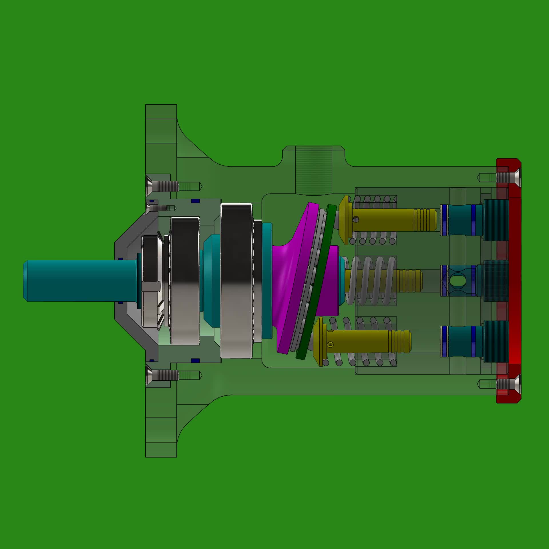
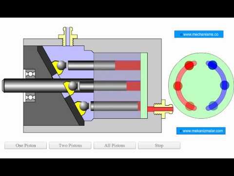
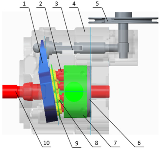
Axial plunger motorsThe working principle of axial plunger motors is that the oil distribution plate and the swash plate are kept in their original place, while the motor shaft rotates together with the cylinder connected to it. When the pressure oil enters the cylinder’s plunger hole through the window of the oil distribution plate, the plunger extends out driven by the pressure oil and closely sticks to the swash plate, following which, the swash plate produces a reactive force against the plunger, which can be split into an axial force and a vertical force Q. Q is balanced with the hydraulic pressure on the plunger, and Q enables the plunger to generate a torque against the center of the cylinder, driving the motor shaft in negative rotation. The instantaneous total torque generated by the axial plunger motor is pulsating. If the input direction of pressure oil is shifted, the motor shaft will move in positive rotation. Changes in dip angle of the swash plate, namely, the variations of displacement affect not only the motor’s torque, but also its speed and rotary direction. The greater the dip angle, the greater the torque produced and the lower the speed.

The number of components in any hydraulic power unit may vary depending on the complexity of the system. Normally, all these depend on the specific applications of the power unit.
I will make the entire discussion simple and easy to understand. This is because you need to evaluate every component before buying the hydraulic power unit.
In a hydraulic circuit, electric motors convert the electrical energy into a rotational force that drives the pump gear. You’ll learn more about pump gears in section 3.2 of this chapter.
The electrical DC motors convert direct current into a rotational mechanical energy. These motors use a direct power supply whose voltage may vary from DC12V, DC24V, DC48V or DC96V; depending on the design specification of the hydraulic power pack system.
These motors are common in most micro or mini hydraulic power packs. This is because the DC power supply is portable thus, a perfect choice for mobile of portable hydraulic equipment.
For large DC motors that are commonly found in large hydraulic systems, the electric motor manufacturers use electromagnet instead of permanent magnets.
The complexity of the design will depend on the type load the motor should drive. In the case of the hydraulic power packs, we have a hydraulic pump as the load.
In the recent past, a number of hydraulic power pack manufacturers have adopted the permanent magnet and brushless DC motors for most pump applications. The brushed wound field DC motors are still common in some hydraulic applications.
Quite a number of AC hydraulic power packs use induction motors. The most common types of induction motors are:Three phase induction AC motors – requires three power phases
A hydraulic pump is a device that converts the mechanical energy from the motor (rotary motion) into a hydraulic energy. The output shaft from the electric motor is coupled to the shaft of the hydraulic pump.
As the pump rotates, it creates a pressure difference between its inlet and outlet. This pressure difference helps the pump to draw hydraulic fluid from the tank.
It then pushes the hydraulic fluid through the tubes/pipes to the hydraulic cylinder parts or hydraulic motor. In this section, I will focus on the following types of hydraulic pumps:Gear pumps
As you’ll realize in sections 3.2.1, 3.2.2 and 3.2.3, this classification is based on the structural design of these pumps. In each category, I will:Explain the working principle of the pump
As the gears rotate, they create a suction effect at the pump’s inlet and the fluid is drawn into the pump chamber. The rotation directs the hydraulic fluid between the teeth of the gears and the walls of the pump and finally to the output.
In most cases, it is one shaft of the gear that is coupled to the electric motor. Thus, the movement of the second gear (driven gear) occurs as the other gear (driving gear) engages it when the pump is operating.
The herringbone and helical gears in these hydraulic pumps offer a smooth flow than spur gears. The flow rate of these gears is determined by a number of features such as:Size of volume between the gear teeth
These hydraulic pumps have an externally-cut teeth that are contained in and meshed another gear that has an internally-cut teeth. Liquid is drawn when the gears come out of mesh and is discharged when the gears mesh together.
These pumps use their contracting and expanding cavities to move hydraulic fluids from the cylinder to the tubes. This is possible with the help of an electric motor that creates motion, pistons and check valves.
Hydraulic pistons undergo a reciprocating motion (moving up and down or back and forth), thereby building a pressure that forces the fluid through the tubes.
It has a cylindrical block with pistons that move in the direction of its centerline. They have simple designs and guarantee reliable operation.Radial Piston Pump
Its pistons are attached to cylindrical block, forming a wheel like structure. The rotation of the cylindrical block causes a back and forth motion within the pump.
This fluid flows into the hydraulic vane pump chambers. The volume of the vane chambers at the inlet sections is larger than that at the outlet section of the pump.
These pumps can be classified further as either unbalanced or balanced vane pumps. Most opt for the balanced vane pumps because they have better speed ratings, high pressure and increased bearing lifetime.Variable displacement vane pumps
Like other hydraulic pumps, the vane pumps may not be suitable for certain pumping applications. Here are the main advantages and disadvantages of these pumps.
Type of materials for these main sections:Shaft seal – Component mechanical seals, industry-standard cartridge mechanical seals, and magnetic-driven pumps.
With these two main components of the hydraulic power pack (electric motor and pump), your systems should draw the hydraulic fluid, ready to supply it to the circuit.
A hydraulic manifold helps to regulate the fluid flow, pressure and flow direction in hydraulic systems. It acts a junction between the hydraulic pump and hydraulic actuators.
The hydraulic manifold design may vary depending on the types and number of control components. With the help of various hydraulic manifold valves, you can easily monitor and control the fluid flow.
As you’ll realize later in this section, these hydraulic manifold blocks mainly vary depending on how hydraulic valves are interconnected to each other.
The hydraulic central manifold has several multiple options you can use for integral solenoid, mechanical operated hydraulic valves and an interface for custom designed valves.
For more complex and flexible functionalities, you can use the hydraulic stacked manifold. This helps to combine multiple functions into one assembly such as reducing the possibility of pressure drop.
This is actually the main reason why you should consider a stacked manifold block as an extra section of the hydraulic center block. You can use it when the space in the central manifold cannot hold more valves or large size cartridge valves.
Target has delivered thousands hydraulic power units for different applications around the world. These include a series of standard hydraulic manifolds that are commonly used in most hydraulic power packs.
At times, the standard hydraulic power packs may not meet the specific requirements of your applications. In such cases, you should opt for customized hydraulic manifold blocks that meet your specific requirements
Apart from the hydraulic manifold blocks, I need to introduce you to the actual components that control the hydraulic fluid. This is the hydraulic valves.
Valves are devices that control the flow of fluids in hydraulic systems. They regulate flow by cutting-off, diverting, providing an overflow relief and preventing reverse flow of the hydraulic fluid, among other functions.
There are very many hydraulics valves available in the market. However, for the scope of this eBook, I will focus on the following:Hydraulic check valves
As you can see, there are many types of hydraulic cartridge valves available in the market. These valves are suitable for high flow rates and leak free control systems such as hydraulic power packs.
A hydraulic check valve allows fluid to flow through it in one direction, i.e. it prevents a reverse flow. For this reason, it is also referred to as one-way valve or non-return valve.
Since the check valves provide unidirectional flow, thereby providing a sealing against the reverse flow, it is advisable that you install them on the outlet side of the hydraulic pump. Below, is an image showing how a hydraulic check ball valve functions:
In hydraulic power pack circuits, you’ll mount the internal check valve in the block, while the external check valve on mounting hole found on the surface of the valve block.
Manufactures use different materials to produce check valves such as zinc plated carbon body and hardened stainless in-line poppet. This aims to provide a long-lasting metal-to-metal seal.
At times, hydraulic power pack manufacturing companies may include a pilot operated check valve. You can control these valves using fluids from other valves.
A hydraulic pilot-operated check valve is unique in the sense that; they allow hydraulic fluid to flow in one direction, but, you can still disable them using a pilot pressure.
In hydraulic circuits, relief valves protect the downstream circuits from over pressurization. They are a good example of a safety valve and you may also refer to them as pressure relief valves (PRV).
During the period of work cycles, these pilot operated relief valves unload the pump at low pressure. Another important classification criteria is the type of material.
A number of adjustable hydraulic pressure relief valves are manufactured from zinc plated carbon steel bodies. They have hardened stainless steel sealing components.
You’ll find that when the pressure is reduced within 25% of the set point, the valve will automatically reseal. Below is the actual image of a hydraulic relief valve:
Below are seven crucial parameters you need to consider when buying a pressure valve:Pressure rating; it should be compatible with your hydraulic power pack system pressure.
In most applications, a hydraulic release valve also means a 2 way 2 position hydraulic cartridge solenoid valve. Solenoid valves are electromechanical operated valves.
Such valves have a fast and a safe switching mechanism. They are also: reliable, durable, compact in design and offer low control power. Below are examples of hydraulic release valves:
It’s the electric current that makes it a two-way valve. Where, it will allow the hydraulic fluid to return to the tank, thereby, releasing the load of the cylinder.
Owing to the varying circuit designs of directional control valves, you’ll find quite a number of hydraulic control valves and valve block mounting dimensions.
Normally, you can adjust hydraulic solenoid valve depending on the type of control mechanism of a specific application. Moreover, the complexity of a directional control valve will also depend on the specific hydraulic system you intend to control.
In most hydraulic circuits, you can install them near delicate gauges that may get damaged in case of a sudden pressure surge. Also, you can use these throttle valves in the pipes returning oil back to the tank.
Needle valves can handle a wide range of pressures. Depending on the nature of the hydraulic fluid system, a needle valve can handle the pressures that range from 5,000 to 6,000 psi.
Some of the most common materials include carbon steel, stainless steel or brass. Each material has unique physical and chemical properties making them suitable for specific hydraulic applications.
The complexity of the design will depend on the specific application of the directional valve in a hydraulic control circuit. In hydraulic circuits, the directional control valve symbol is:
Modular valves provide a wide range of mounting options in hydraulic circuits. They have a number of mounting holes, valves and loops compared to cartridge valves.
You can fit them in any system to fulfill the specific hydraulic circuit requirements. At the moment, there is a wide range of modular valves available in the market such as pilot operated check valves, flow control valves, pressure reducing valves and counterbalance valves.
The hydraulic flow valves are available in a wide range of configurations and designs, depending on the functional purposes of each valve. A good example is a modular flow control valve with a directional control valve and a sub plate.
As you can see, there are very many types of modular valves. Therefore, you need to review the manufacturer’s data sheet to choose a modular design that best suits your hydraulic system.
Throughout this section, I believe you have noted that there are very many types of hydraulic valves. Always choose one that best suits your hydraulic power pack.
Remember, with an appropriate valve, you can have full control of the fluid flowing through the hydraulic pipes. Now, let’s discuss the next component of a hydraulic power pack.
A hydraulic tank is a container that holds the fluid that you’ll supply to the system to do the work. At times, you may refer to it as a hydraulic reservoir.
Hydraulic oil tanks for power pack units come in a wide range of shapes, sizes and materials. For the scope of this eBook, I will focus on the following:Hydraulic plastic tanks
Quite a number of hydraulic plastic tanks are made from polypropylene (PP). This is a special oil tank material that is resistant to corrosion, low temperature, high temperature, acid-alkaline solutions and solar radiation.
Most manufacturers use an injection molding technique that results in a light weight and strong hydraulic fluid tank. The tank can withstand high pressure and resistant to diverse weather conditions.
The size may vary depending on both design and size of the hydraulic power pack. The volume of the tank should be large enough to allow for all hydraulic fluids in the pipes to drain in the tank.
Therefore, you’ll find that the hydraulic fuel tank size may vary depending on the hydraulic equipment such as hydraulic stacker, hydraulic lifting equipment, hydraulic dock ramp, hydraulic scissor lift, etc.
Like the plastic hydraulic reservoir tanks, the hydraulic steel tanks are available in a wide range of sizes and designs. Unfortunately, for these hydraulic power pack steel tanks, you’ll need a liquid meter to determine the level of hydraulic fluid.
Basically, these tanks are specifically manufactured to resist high and low temperature conditions. They ensure the properties of hydraulic fluid remains the same at all times.
This allows air to get into the tank, thereby protecting the tank from atmospheric pressure. Remember, as the gear pump rotates it creates a vacuum that forces hydraulic fluid into it.
You will mount hydraulic power pack to the other customized steel tank through the steel tank neck. So, you can mount one or two or more power packs on one steel, square customized steel tank.
A coupling is the main device you’ll use to connect your electric motor and hydraulic pump. That is, you’ll connect the shaft of your motor to that of the hydraulic pump.
The type of coupling will depend on the position of your electric motor relative to that of the hydraulic pump. Some of the most common types of coupling include:Flexible coupling; this is when the coupling can handle both parallel and angular misalignment.
To ensure there is a seamless flow of hydraulic fluid from the tank to the cylinder, you’ll need the following:Fittings; this connects the hose to the outlet of the manifold if they don’t match.
Hydraulic pipes and filters play an integral role in hydraulic power pack systems. In this sub-section, you’re going to learn about:Hydraulic suction pipe
As the hydraulic pump rotates, it creates a pressure difference, hence, the fluid flows to the pump. A hydraulic suction pipe is the pipe that connects the tank and the pump.
Hydraulic filters remove debris or impurities in the oil before it is suctioned through the hydraulic pipe to the pump. It helps to keep the hydraulic system clean.
These filters come in different sizes and configurations with some equipped with magnet to remove metallic parts from the hydraulic fluid. This prevents clogging.
These are basic components of hydraulic power packs that depend on electrical signals to send commands to the system. In this subsection, you’ll learn about three major components:Cable remote-push button pendant
Commonly used for single / double acting hydraulic system. There was a key you can lock this remote away from battery, so, nobody can operating power pack without this key. It has four wires, which are 4 meters4 buttons Remote
A hydraulic actuator is the mechanical portion that converts hydraulic power into useful mechanical work. This mechanical work can either be linear motion, rotary motion or oscillatory motion.
A valve actuator refers to the mechanism of opening and closing a valve. Some of the most common types of valve actuators include manual, pneumatic, hydraulic, electric and spring valve actuators.
Linear actuators create motion in a straight line. You can create motion using different mechanisms that may involve the use of mechanical, hydraulic, pneumatic, piezoelectric or electro-mechanical actuators.
The electro-hydraulic actuators are commonly used in applications that require a high degree of precision. They have self-contained actuators, which are operated only by electric power.
In chapter 1, section 1.2 (sorts of hydraulic power pack) and section 1.3 (function of hydraulic power), I did discuss all the vital aspects about single acting and double acting hydraulic cylinders.
Just as a reminder, you should know that hydraulic cylinder is an important hydraulic actuator. It converts hydraulic energy into a mechanical energy we use to perform a number of tasks.
As you have learnt earlier, hydraulic power packs are broadly categorized as either single acting hydraulic cylinder or double acting hydraulic cylinder. So, this fact does not change in hydraulic cylinder actuators.
A position-sensing hydraulic cylinder is used in more advanced systems where it provides an instantaneous analog or digital electronic position feedback information. That is, it indicates the extent of rod extension during any stroke.
As you have seen earlier (chapter 1), all these hydraulic power packs have their unique advantages and disadvantages. You will learn more about this in chapter 5.
That is, a hydraulic motor can generate different magnitude of torque at different pressures. Some of the main applications include hydraulic bicycle and hydraulic hybrid vehicle.
Before it begins to rotate, the hydraulic fluid should provide sufficient torque to turn the motor. The torque that the hydraulic fluid provides can be categorized as:
This is the minimum torque you’ll need to start the motor at no load. That is, the hydraulic energy should overcome the internal frictional forces of the motor.
The existing hydraulic motors may be classified into four different categories. These include:Hydraulic gear motors; they include hydraulic and epicyclic gear motors.
The truth is, hydraulic pumps add more energy to the circuit by pushing the fluid while the hydraulic motors act as actuators that change hydraulic energy into rotary motion. Furthermore, hydraulic pumps are coupled to an electric motor.
The concept of hydrostatic transmission is based on the fact that, whenever a pump is connected to a prime mover, it generates fluid flow that drives a hydraulic motor. It is this hydraulic motor that is connected to the load.
To make it more versatile, you can make either the pump or motor variable displacement. You can learn more about this concept here: Understanding Hydrostatic Transmissions.
This is breaking mechanism that uses brake fluid (hydraulic fluid) to stop or control a moving wheel or object. You can review hydraulic power pack applications in chapter one to learn more about this.
Hydraulic fluid is the medium through which power or energy is transferred in hydraulic systems. Some of the most commonly used hydraulic fluids are either mineral or water based solutions.
Basically, these are the basic aspect you need to know about hydraulic fluid. To learn more about these oils then you can click: Engineering Essentials: Hydraulic Fluids.

Avoid any downtime at your construction site with the range of swash plate pump from Alibaba.com. You can check out the fully-stocked parts at Alibaba by manufacturer and model and affordable wholesale prices. The wholesale swash plate pump collection of spare parts from China’s wholesaler, Alibaba, fits well with a wide range of heavy-duty equipment, from bulldozers, excavators, and hammers, among others. Plus, you can find parts for your tractors, skid steer loaders, wheel loaders, backhoe loaders, and crawler dozers.
If you have a limited cash allocation, the used or remodeled parts will go a long way in accommodating your budget. Alibaba’s swash plate pump and tools make it easy to replace, modify and enhance your equipment for their optimal performance. For electrical and mechanical applications, you can find your match at Alibaba.com for everything you need to make your vehicle perform better. Get engine oils, batteries, hydraulic parts, transmissions, injectors, hoses, and starters from the swash plate pump at Alibaba.com.
The new parts from manufacturers have warranties, and you can buy them by matching the part numbers. Such parts, including hoses, plugs, or filters, will help you quickly deal with downtime on site. The used parts, on the other hand, sell for a lower price. Remember, Alibaba partners with sellers who have certificates of operation. So, you can use these second-hand swash plate pump to get your heavy machine running. You can also get rebuild models from the collection at Alibaba.com. These are sustainable choices that use recycled materials and perform as well as the new parts. And depending on your seller of choice, you might get a warranty to accompany them.
Main Pump Specification EC460B-10-01 Main Pump Ports Location EC460B-10-02 Main Pump Sectional View EC460B-10-03 Main Pump Flow Adjustment EC460B-10-04 Main Pump Control System EC460B-10-05 Main Pump Circuit EC460B-10-06 Regulator Sectional View EC460B-10-07 Regulator Exploded View EC460B-10-08 Regulator Animation EC460B-10-09 Main Pump Control Curve EC460B-10-10 Regulator Adjustment EC460B-10-11 Power Shift Valve Structure EC460B-10-12 Power Shift Valve Output Pressure EC460B-10-13
Gear Pump Specification EC460B-10-14 Gear Pump Structure EC460B-10-15 Gear Pump Sectional View EC460B-10-16 Gear Pump Exploded View EC460B-10-17 Servo Pump Pressure Adjustment EC460B-10-18
CLICK THE VOLVO-LOGO INMAIN THE LOWER RIGHT CORNERMENU TO RETURN TO THIS MENUMain Pump Specification Classification Unit Specification
Model K3V180DTH10TR-9N2B Type Variable displacement, swash plate type, piston pump
Model Code K3V Series 180 Size (Displacement : cm3 /rev) DTH Tandem type double pump with booster 10T Design Serial Number R Shaft rotation view from shaft end(Right) 9N2B Regulator type
Volvo Construction Equipment EC460B-10-04Korea Ltd.Main Pump Control System Hammer Pressure Flow Sensor Control MCV Valve
Volvo Construction Equipment EC460B-10-09Korea Ltd.Main Pump Control Curve 13 K 10 K 172 K 187 K 345 L 340 L 332 L 256 K 333 L 328 L 350 1 I= Pum 0m p 300 A( (2n 40 K pf d =0 P= 320 L
Volvo Construction Equipment EC460B-10-13Korea Ltd.Gear Pump Specification Classification Unit Specification
Model Code P315 Pump model B Drive shaft : B-SAE "B" 13 teeth B Mounting flange type : B-SAE "B" 2- Screw 20.3 P1 Pump displacement : cm3 /rev 15.2 P2 Pump displacement : cm3 /rev 15.2 P3 Pump displacement : cm3 /rev R Shaft rotation view from shaft end(Right)
Volvo Construction Equipment EC460B-10-14Korea Ltd.Gear Pump Structure Without option pump S1
Volvo Construction Equipment EC460B-10-16Korea Ltd. 13Gear Pump Exploded View 13 2
The Positive Displacement Pump Training Course has been developed to assist in Pump Maintenance and Operation. It covers both Reciprocating Pump Working as well as Rotary Pump Working Principles. Explicit Graphics and Animation give an in-depth understanding on working details of various pump types like Screw Pump Working and Gear Pump Working. The training course, designed with extensive Graphics and Animation, gives a virtual Detailed Practical exposure on a large number of Positive Displacement Pumps Types like Gear, Lobe, Vane, Screw, Peristaltic, Metering, Power, Diaphragm, Piston, Beam, Hydraulic, etc. with a detailed Pump Classification. The course also includes an Interactive, Graphically supported Troubleshooting Guide.
The Positive Displacement Pump Training Course (Reciprocating Pump Training and Rotary Pump Training) covers both the Rotary Pump Working and Reciprocating Pump Working. The Training course covers a large range of Pump types like Screw, Gear, Lobe, Vane, Peristaltic, Metering, Power, Diaphragm, Axial Piston Pump, Swash Plate, Wobble Plate Piston, Bent Axis, Radial Piston Pump, Variable Displacement, Sucker Rod, Hydraulic, Beam, etc.
The primary focus on Pump Graphic / Positive Displacement Pump Animation (Reciprocating Pump Animation and Rotary Pump Animation) in the CBT helps in very clearly understanding the Pump Working Principle. The Working principles of various pumps like Screw Pump Working and Working of Gear Pumps are easily understood by the intricate Pump Animations.
The Positive Displacement Pump Training Program has a dedicated module to assist Rotary and Reciprocating Pump Troubleshooting. Animated Cut-Sections clearly explains Rotary and Reciprocating Pump Working and gives a Deep Insight into Pump Operation and how Pumps Work.


 8613371530291