
swash plate hydraulic pump animation price

Piston design - Solid, hollow, or with piston rings. The design and weight of the pistons will have a major effect on pump efficiency. The Parker F11 design with its lightweight head and retained balls can reach significantly higher speeds than swashplate pumps with their longer, heavier pistons.
Some pumps and motors can run over-centre, which means they can provide flow or rotate their drive shaft in both directions. These are commonly used in closed circuit, mobile vehicle drives systems.
Bent axis designs tend to have much heavier duty shaft bearings than swashplate pumps. This is because they are more commonly used as motor drive units and have to take the wheel loads against their shaft. Swashplate pumps, on the other hand, tend to be driven through flexible couplings that will remove any side loads, so the internal bearing is sized just to take the internal loads from the dynamic and pressure loading forces.
Noise level can be an issue with piston pumps. The noise is generated by the discontinuities in the flow e.g. as the pistons move forward and backward they create a pulsating flow that passes into the complete hydraulic system and vibrates or radiates from other components further down the circuit. This flow discontinuity is further complicated by the supply port which connects and disconnects each piston as it rotates. The timing of the opening and closing can create other, higher frequency flow discontinuities. Often different timing plates are available for different operating conditions e.g. fixed speed or variable speed applications.
Case leakage line pressures are critical for controlling the pressure balance of the slipper against the suction pressure. Care should be taken with some pump controllers as the valves exhaust into the pump casing and can create dangerous pressure spikes. Make sure case drain lines are sufficiently sized. One possible solution may be to use a more compliant, clear plastic hose for the case leakage line which will have the effect of damping out these peaks before damage the slippers. Case leakage line temperatures are also a good way of monitoring the health of the pump as discussed in the vane pump section.
If you are in doubt about the most appropriate pump to use in your application then always talk to manufacture or distributor who should be able to offer the most appropriate pump range and advise the expected service life.
The pump model is represented by the subsystem named Axial-Piston Pump. The prime mover rotating the pump is simulated with the Ideal Angular Velocity source. The pump output passes through a pipeline, control unit, and a variable orifice that acts as a load. To test control unit response to variable load, the orifice changes its area during simulation. The change profile is implemented by the Spool Pos subsystem.
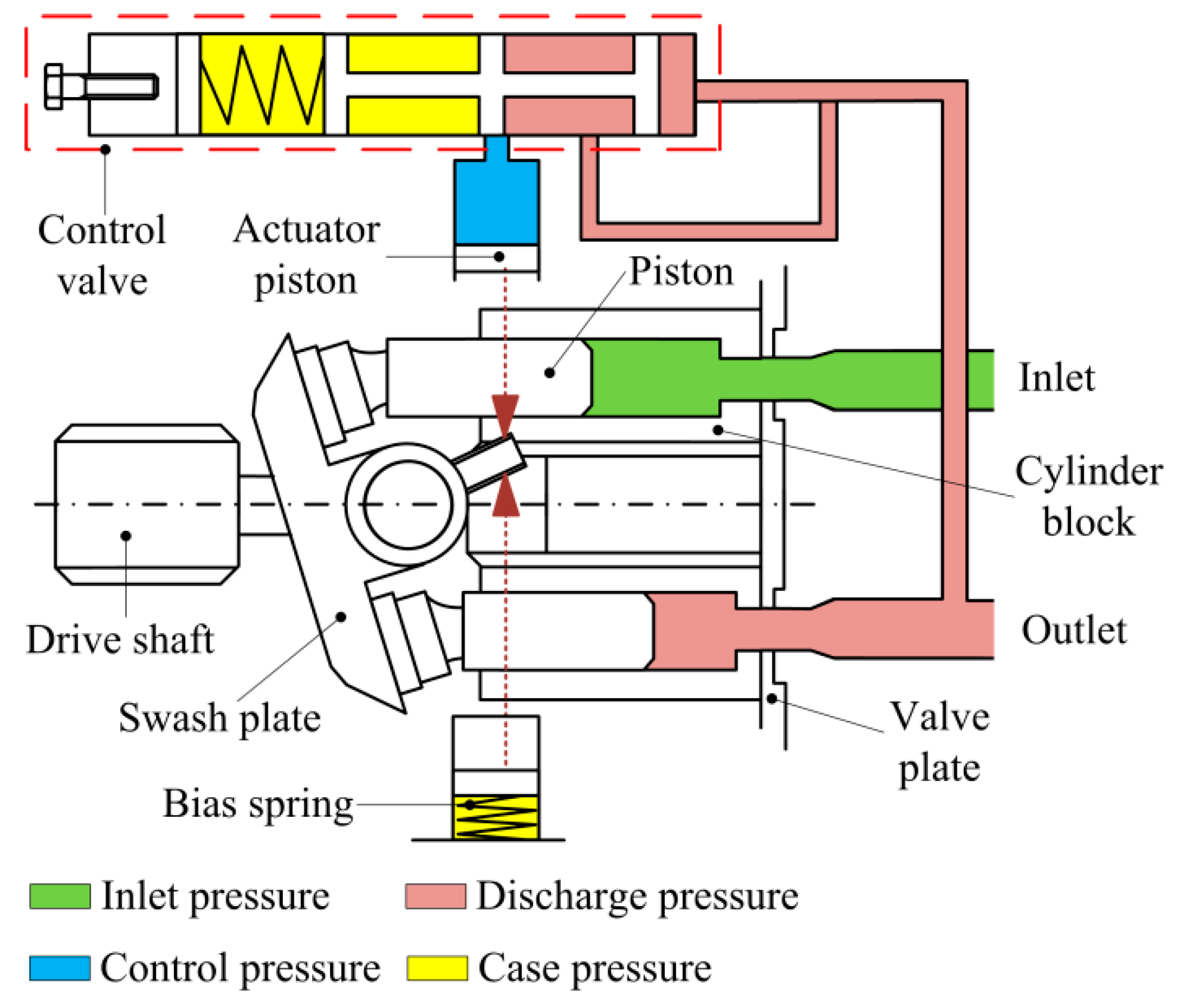
The control unit in the test rig is represented by the subsystem named Pressure/Flow Control Unit. The load-sensing function of the pump control uses a fixed orifice. The control unit keeps the pressure differential across this orifice constant, regardless of pump loading. The control unit receives signals on pump output pressure and load pressure, measured after the flow control valve. Based on these pressures, the unit produces yoke displacement, which affects the angular position of the angled swash plate in the pump. This helps maintain the specified pressure differential across the flow control valve and prevent pump pressure from exceeding the preset value.
Every piston of the pump is represented by a subsystem called Piston. These subsystems are identical and are connected to the following external ports of the pump model:
The suction ports of all pistons (ports A) are connected to the output of a low pressure booster pump, which is simulated with the Ideal Hydraulic Pressure Source block. The output pressure of the booster pump is set to 5e5 Pa.
The yoke is connected to the Y ports of all pistons, thus acting on the angled plate of the swash mechanism. The displacement of the yoke is limited by the hard stop.
The model of the piston (Figure 4) is based on the Single-Acting Hydraulic Cylinder block, which is mechanically connected to the drive shaft through the Swash Plate block. The cylinder is also hydraulically connected to ports A and B through the Porting Plate Variable Orifice blocks. Ports A and B represent pump discharge and intake ports, respectively.
Let us assume that the first piston (marked P1 in the schematic) is located exactly at the reference point that corresponds to the lowest piston position. Let us further assume that port A represents the intake outlet of the pump. In other words, the piston moving along slot A in positive direction (clockwise in this case) goes up, and its chamber is filled with fluid by a booster pump. This means that the Phase angle parameter of the Porting Plate Variable Orifice A in Piston 1 must be set to zero. The same parameter of the Porting Plate Variable Orifice B in Piston 1 must be set to 180 degrees, because it starts interacting with slot B (pump discharge port) only after rotation by 180 degrees.
In the piston model, parameters Phase angle of each Porting Plate Variable Orifice block are denoted as Phase angle A and Phase angle B, respectively. The values of the phase angle for all five pistons are computed in the initialization section of the Axial-Piston Pump subsystem mask editor. The following table shows their values in degrees, with the corresponding values in radians given in parenthesis:
The Swash Plate block in the piston model also requires phase angle to be assigned, to specify the position of a piston with respect to the inclined surface. With the selected reference point, the values of the swash plate phase angle coincide with the Phase angle A values, as shown in the table.
The Porting Plate Variable Orifice blocks require angular position of the respective piston at their input. This function is performed by the Angle Sensor block.
Other important parameters are the stroke of the cylinder and the initial position of the piston with respect to the cylinder cap. The stroke must be large enough to allow the piston to reciprocate even at the maximum angle of the swash plate
In the model, the maximum angle is set to 35 degrees (0.6109 rad) and pitch radius is set to 0.04 m, which makes the stroke to be greater than 0.056 m. The stroke is set 0.06 m. The piston initial positions must be equal to half of the stroke at zero initial swash plate angle. But the initial angle changes its value depending on the initial position of the actuator. As a result, the piston initial positions are computed with the equation
These pressures act on the side faces of the 3-way directional valve and shift the valve proportionally to the pressure difference and setting of the centering springs. The valve connections are selected in such a way that increased pressure differential opens path A-P and closes path A-T. The actuator is arranged as a single-rod differential hydraulic cylinder with rod connected to the pump yoke. The pump displacement is increased if the rod moves in the direction of the arrow shown in the schematic. Due to difference between cylinder effective areas, the displacement is increased if both cylinder chambers are connected to the pump, and decreased if the chamber without rod is connected to tank. As a result, increased pressure differential across the valve causes the pump to decrease its displacement until it returns to preset value. The spring preload of the valve is determined with the equation
The purpose of the pressure limiting function is to prevent pump pressure from exceeding the preset value. It is implemented with the pressure-relief valve and the orifice in the LSP line. The pressure-relief valve is set to the desired maximum value. When pump pressure builds up to this value, the valve opens and causes pressure in the right chamber of the valve to decrease opening path A-P. The actuator shifts to the right until the pressure returns to the preset value.
The model of a load-sensing valve is built using the 3-Way Directional Valve, Hydraulic Double-Acting Valve Actuator, Pressure-Relief Valve, and Fixed Orifice blocks, as shown in the model diagram (Figures 6 and 7).
The pressure differential is set to 20 bar. The 3-Way Directional Valve path A-T must be initially open, to force the pump to increase its displacement at the start of operation. To perform the load-sensing function, pressure increase at the B port (load-sensing port) must open the A-T path and close the A-P path. These are the reasons that determined the valve port connections to the system. The remaining load sensing control valve parameters, such as spring stiffness, valve stroke, valve orifice area, and so on, are tuned in the model to ensure required accuracy, stability, and numerical effectiveness.
The pressure-limiting function is implemented with the combination of the Fixed Orifice and Pressure-Relief Valve blocks. The valve is set to 250 bar. At this pressure, increased flow through the fixed orifice causes pressure at port Y of the Hydraulic Double-Acting Valve Actuator (block Valve Actuator in Figure 7) to drop, which eventually decreases the displacement of the pump.
The cycle starts with zero opening signal, followed by opening of 2.8, 5.2, 1, -0.8, and, finally, 2.45 mm. At the start of the cycle, the pump shaft starts rotating at 260 rad/s (~2500 RPM) with the pump yoke initial position set to 5 mm. The servo cylinder starts increasing pump displacement, pump pressure slowly builds up, and the process settles down at ~0.35 s after the pressure differential across the flow control valve becomes close to preset value of 20 bar. The load-sensing valve is opened at this moment by ~1.2 mm.
At 1 s, the load valve is practically fully closed, causing pump pressure to rise. The load-limiting function becomes dominant as the pressure reaches 270 bar. The pump returns to the load-sensing mode after the pressure falls below the preset value.
The plot below shows the flow rate within the pump pistons and at the load. The cyclic nature of the piston pressures can be seen, as well as the overall behavior of the pump which stays close to its rated flow rate.
The plots show the load sensing and pressure limiting control. The pump maintains its rated flow rate of 1.1 m^3/s even as the load changes, as shown on the pump output pressure plot. However, as the pump output pressure rises to its maximum rated pressure, the pressure limiting control adjusts the yoke position is and the flow rate drops below its rated flow rate.
The Positive Displacement Pump Training Course covers a large range of pump types like Gear Pump, Lobe Pump, Vane Pump, Screw Pump, Peristaltic Pump, Metering Pump, Power Pump, Diaphragm Pump, Piston Pump, Variable Displacement Pump, Beam Pump, Sucker Rod Pump, Hydraulic Pump, etc. with detailed pump classification.
The primary focus on graphics/animations in the training software course helps in very clearly understanding pump maintenance procedures, pump operating/working principle, and aids in pump repair. Included are animated explanations on all types of pumps like Gear Pump, Lobe Pump, Vane Pump, Screw Pump, Peristaltic Pump, Metering Pump, Power Pump, Diaphragm Pump, Axial Piston Pump, Swash Plate Piston Pump, Wobble Plate Piston Pump, Bent Axis Piston Pump, Radial Piston Pump, Variable Displacement Pump, Beam Pump, Sucker Rod Pump, Hydraulic Pump & Mud Pump. The positive displacement pump training program has a dedicated module to assist pump troubleshooting. Animated cut-sections gives a deep insight into pump operation and how pumps work.
Students, as well as maintenance and engineering personnel, and those who have not had formal training, will find that this computer-based training program on positive displacement pumps increases both their knowledge and confidence when performing maintenance. Those with previous training may find this program a good refresher and may learn some important information not covered in their original training.
The course on Positive Displacement Pumps is also available in a "Hardware Lock" licensing method. Many users have requested that they be able to use the software on multiple computers, i.e. when working with the program on the office computer and on the home computer. This Hardware Lock method allows users to install software on as many computers as they like. They need only enter the key on whichever computer they are currently wanting to use the software on. This copyright method also works great for the classroom environment.
- The guide is customized to troubleshoot problems on individual pump types.Symptoms:Rotary Pumps:- No Liquid Delivery- Insufficient Discharge Pressure- Insufficient Capacity- Starts, but Loses Prime- Excessive wear- Excessive Heat- Excessive Noise and vibration- Excessive Power Demand- Motor Trips- Elevated Motor Temperature- Elevated Liquid TemperatureReciprocating Pumps:- No Liquid Delivery- Insufficient Capacity- Short Packing Life- Excessive wear at Liquid End- Excessive wear at Power End- Excessive Heat at Power End- Excessive Noise and vibration- Motor Trips6. Conventional and Interactive Skill Tests with Evaluation
Parker PVplus axial piston pump with variable displacement has been designed and optimized for demanding use in heavy duty industrial and marine applications. With pressure ratings of up to 420 bar and high-speed ratings this open circuit, swashplate principle axial piston pump provides high productivity and power density to its users. Beside its robustness and exceptionally long service life, PVplus is also characterized by a very high conversion flexibility. As a standard every PVplus comes with an integrated pre-compression volume which ensures low ripple operation and reduced noise emissions. A wide range of displacements and control options allows for a wide range of applications.

In the parts tables below you may select the hydraulic parts you need. All PVplus parts we sell are genuine Parker Hannifin and originate in Germany. We highly recommend to use genuine OEM parts only to ensure smooth operation and longer service life.
The Parker PVplus hydraulic pumps are produced in Chemnitz, Germany and manufactured by Parker Hannifin Manufacturing Germany GmbH & Co. KG. The PV028R1L1T1N001 is an axial piston pump of variable displacement with a maximum displacement volume of 28.0 ml/rev. The mounting interface is according to metric (ISO 3019-2) and the pump control group is without control. Further details are listed in the Parker PV028 Datasheet.
All pump repair kits listed on this page are for Parker PVplus axial piston pumps of latest design series. Current design of Parker PVplus PV028 is 45 Design (hydraulic pump) and Design (pump controller). The item numbers listed in these tables refer to the PV028 exploded view drawing of the Parker PV028 Spare Sparts List PVplus Design 45. Should you require spare parts for an older design PVplus pump, please contact us for further information (do not forget to include pump name plate information).
Be sure to operate the hydraulic pump under optimum oil viscosity (not too low) since a thinner lubrication film causes more direct metal to metal contact resulting in increased wear in glide and roller bearings. The PVplus bearing kit contains both the front and rear roller bearing of the drive shaft and are also included in the pump shaft repair kit. The PVplus trunnion bearing unit contains the two glide bearings of the pump swash plate (trunnion bearings are not included in swash plate kit).
The axial piston pump type V60N is designed for open circuits in mobile hydraulics and operate according to the swash plate principle. They are available with the option ...
Variable displacement axial piston pumps operate according to the bent axis principle. They adjust the geometric output volume from maximum to zero. As a result they vary the flow rate ...
The K3VG series are swash-plate type axial piston pumps which give excellent performance in high flow industrial applications in a compact and cost-effective package.
Closed circuit axial piston pumps are used as hydrostatic transmission components in self-propelled machines and for rotary drives in both fixed and mobile equipment of all kinds.
Twin flow axial piston pumps offers two different flows. In addition, we find several advantages such as lower weight or standar system solutions. BZT are available in ISO and SAE version.
Our variable volume, pressure compensated axial piston pumps continuously match output flow to the system demands. They’re designed to closely match the Eaton-Vickers PVB and PVQ and ...
The PFBA is a fixed displacement pump, axial-piston pump. It’s proven itself in a variety of operations—including die casting and injection molding machines, high-pressure ...
PMH high pressure axial piston pumps for closed loop are specifically designed to be used on heavy duty machines for traction and auxiliary functions, providing efficiency and durability.
Variable displacement pumps in closed loop; 3 basic design units and 8 max. displacement sizes of 14, 18, 21, 28, 35, 46, 56, 64 cc/rev; various control options; max. nominal pressure 300 bar, 350 bar peak; driving speed: ...
"C"" Axial Piston Pumps for high accuracy fluid metering with precision flow controls and high-pressure capability. Specifically designed for the Polyurethane Industry. Capacities from ...
Rotork offers a range of high quality hydraulic pumps for applications in the upstream and downstream oil and gas industries. These include an extensive range of axial piston ...
... Parker’s hydraulic truck pump series F1 featuring high self-priming speed and high efficiency and is one of the leading truck pumps in the market. The F1 pump provide ...
Parker P2/P3 High Pressure Axial Piston Pumps are variable displacement, swashplate piston pumps designed for operation in open circuit, mobile hydraulic ...
... Series pump offers variable displacement axial piston pumps for open-circuit applications. Featuring a compact footprint and continuous operating pressure ...


 8613371530291