
swash plate hydraulic pump animation quotation
Piston design - Solid, hollow, or with piston rings. The design and weight of the pistons will have a major effect on pump efficiency. The Parker F11 design with its lightweight head and retained balls can reach significantly higher speeds than swashplate pumps with their longer, heavier pistons.
Some pumps and motors can run over-centre, which means they can provide flow or rotate their drive shaft in both directions. These are commonly used in closed circuit, mobile vehicle drives systems.
Bent axis designs tend to have much heavier duty shaft bearings than swashplate pumps. This is because they are more commonly used as motor drive units and have to take the wheel loads against their shaft. Swashplate pumps, on the other hand, tend to be driven through flexible couplings that will remove any side loads, so the internal bearing is sized just to take the internal loads from the dynamic and pressure loading forces.
Noise level can be an issue with piston pumps. The noise is generated by the discontinuities in the flow e.g. as the pistons move forward and backward they create a pulsating flow that passes into the complete hydraulic system and vibrates or radiates from other components further down the circuit. This flow discontinuity is further complicated by the supply port which connects and disconnects each piston as it rotates. The timing of the opening and closing can create other, higher frequency flow discontinuities. Often different timing plates are available for different operating conditions e.g. fixed speed or variable speed applications.
Case leakage line pressures are critical for controlling the pressure balance of the slipper against the suction pressure. Care should be taken with some pump controllers as the valves exhaust into the pump casing and can create dangerous pressure spikes. Make sure case drain lines are sufficiently sized. One possible solution may be to use a more compliant, clear plastic hose for the case leakage line which will have the effect of damping out these peaks before damage the slippers. Case leakage line temperatures are also a good way of monitoring the health of the pump as discussed in the vane pump section.
If you are in doubt about the most appropriate pump to use in your application then always talk to manufacture or distributor who should be able to offer the most appropriate pump range and advise the expected service life.

Axial piston pumps are a common part throughout construction machines and across construction equipment brands. Their design allows them to be used from the cooling system to the steering system to a multitude of places throughout a machine. Anyone who has worked in construction equipment has certainly come across an axial piston pump, but one might still wonder, “What exactly is going on in this little box?” That’s why we’re here to help.
Whether you’re researching an axial piston pump problem or you’re just inquisitive about this widely-used part, read on for a short explainer on how they work and what they do.
At its most basic, an axial piston pump turns mechanical energy (the turning of a shaft) into hydraulic output (the moving of fluid). The use cases for an axial piston pump are wide-ranging, leading to the adoption of this pump design throughout construction equipment types and across construction equipment brands. An axial piston pump provides advantages in dependability, simplicity, and efficiency leading to its use in handling a wide range of tasks on a machine.
The basic mechanics and design of an axial piston pump are also commonly combined with gearing designs to create axial piston motors. An example is the swing motor commonly found in excavators which combines the design with planetary gears to power the rotation of the house at the point where it spins relative to the tracks.
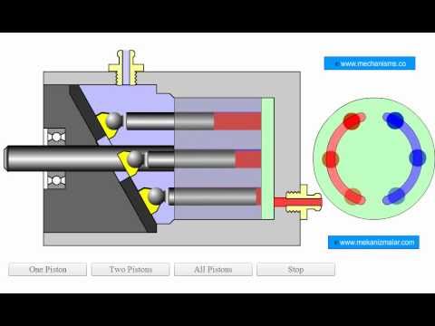
Seeing the rotation of the piston barrel and the back and forth action of the pistons clearly illustrates how the axial piston pump works. » Click video to play/pause animation.
To convert mechanical energy into hydraulic output, an axial piston pump utilizes a rotating, splined drive shaft that connects to and turns a piston barrel. To create the pumping mechanism of the pump, piston pumps can use either a swash plate design (featured in video) or a bent axis design.
In both designs, as the pistons rotate they are repeatedly drawn away from a valve plate and then pushed closer to the valve plate. This variation in distance alters the size of the chamber available to hold hydraulic fluid. At times when the gap between the end of a specific piston and the valve plate is decreasing, the chamber will shorten, and hydraulic fluid will be expelled through the valve plate. As the piston rotates, it will eventually reach a point where the gap is increasing, leading to a longer chamber. This vacuum will cause hydraulic fluid to be drawn into the chamber through the valve plate.
Since the valve plate acts as a divider between the input and output sides of the pump, as the pistons and piston barrel rotate, hydraulic fluid will be continuously cycled through the pump as it is drawn from one connection and directed with force into another.
Since the rotating of the pistons and piston barrel is determined by the rotation of the shaft, the pump"s output can be controlled by increasing and decreasing the speed of the shaft. In the swash plate design, further control of the pump is possible by adjusting the angle of the swash plate, changing the distance of the pistons from the valve plate, and, in turn, increasing or decreasing the size of the chamber available to hold hydraulic fluid.
The shaft distributes mechanical, rotational force to the pump. Splines on the shaft interconnect with splines in the piston barrel to turn the barrel and pistons while splines on the part of the shaft that extends from the housing connect to the machine.
Pistons inside the pump rotate around the center shaft. Since the plane at which one end of the piston is attached is set at an angle determined by the swash plate, the pistons also vary their distance from the valve plate as they rotate. This variation causes a continuous alternation in the depth of the cavity available to hold hydraulic fluid inside the piston barrel and leads to their continuous looping through the pumping process.
In an axial piston pump utilizing a swash plate design, the swash plate is responsible for setting the angle of the piston’s container and, in turn, the amount of variation in depth the pistons will move through. Altering the angle of the swash plate allows the action of the axial piston pump to be further controlled.
The valve plate sits on the end of the piston barrel opposite the pistons. Slots in the valve plate allow fluid to be directed to specific connections for intake and discharge.
Axial piston pumps feature a number of moving parts which always require lubrication and other techniques to decrease friction between moving surfaces. Because of the often rapid speed at which they operate, if an axial piston pump operates in an environment with less than ideal lubrication wear can happen rapidly and even lead to catastrophic failure.
An axial piston pump is often subject to repetitive, long-lasting, and high-pressure work, and with any part subject to those conditions, the buildup of heat over time is always a possibility. Overheating of the pump can be further amplified through inefficiencies developing inside the pump and issues with the overall hydraulic system with which the pump is connected. Examples of each would be: a bearing failure that forces the pump to work harder to maintain expected output and bubbles in the hydraulic fluid inside the pump (cavitation) from operating in a system low in fluid.
Like any part in the hydraulic system, containing hydraulic fluid and directing it in very specific ways is necessary for consistent and expected functioning. If fluid is allowed to flow in unintended ways, the pump will lose efficiency or even lose the ability to provide adequate output. Seals and gaskets are used in axial piston pumps to ensure proper operation, but over time (or due to neglect) seals and gaskets can reach a state of failure that will affect the working ability of the pump.
While a full determination of why an axial piston pump failed can involve a removal and disassembly of the part, often there are simple signs to watch for when one suggests an issue with an axial piston pump, namely:
If the pump begins underperforming during operation and other issues that could affect output like loose hydraulic connections are eliminated, a lack of power can be a sign of internal problems in the pump.
Most axial piston pumps can be expected to create some level of noise, depending on size and design. A pump that has suddenly become louder or begins broadcasting an erratic noise can be a sign that internal parts of the pump are operating outside of proper conditions.
Friction is almost always a byproduct of moving parts and, if unchecked inside the part, it will often show its effects on the outside of the part through heat and/or vibrations. While some heat and vibration is to be expected, especially if the pump is called upon to work for an extended period of time, excess vibration and heating are both a symptom of a problem and a possible escalation of issues.
Most hydraulic systems connect a number of parts in a machine and contamination from failure can often come from any of them. The discovery of fluid contamination can be combined with the previously mentioned signs to narrow issues to the pump.
An H&R tech is at work in the shop rebuilding an axial piston pump, a fairly common sight in the shop because of the wide use of axial piston pumps in construction equipment.
Here’s to hoping you read this article on axial piston pumps because of a pure curiosity about how they work and function. If though, you’ve arrived here in search of a diagnosis for axial piston pump problems, hopefully, with this information in hand you’re closer to solving your troubles.
As a top dismantler and parts rebuilder for construction equipment, axial piston pumps are a frequent rebuild project in the H&R Recon and Rebuild shops. Big parts to small, our parts technicians brings decades of experience to our rebuild project and we take pride in knowing that experience leads to a part that will outlast and outperform the competition. If you’re in search of a replacement axial piston pump, our Parts Specialist are here to help in your search. Just give them a call.
Hydraulic piston pumps move fluids throughout professional equipment and industrial machinery. They’re known for their high efficiency and are commonly used in high-pressure applications.
There are also two major types of hydraulic piston pumps: axial and radial; both can have fixed or variable displacement; fixed displacement means that the pump is delivering the same amount of liquid or gas each time, while variable means that the amount of gas or liquid delivered may be different each time. Although both are considered piston pumps, each one operates differently.
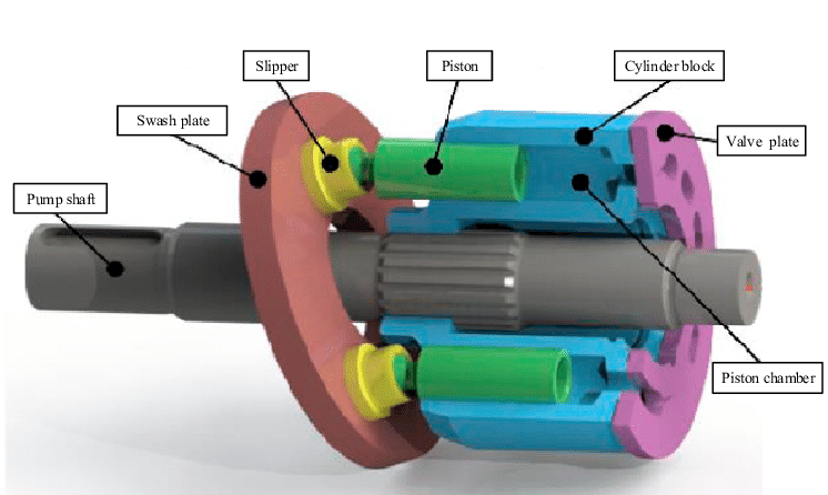
An axial piston pump features four major components: a shaft, swashplate or bent axis, cylinder block, and valve plate. The cylinder block houses the piston pumps, which are laid out cyclically around the drive shaft’s axis (thus why it is named anaxialpiston pump).
The pistons in the cylinder block pump up and down as the drive shaft rotates. The piston’s stroke will vary depending on how it is angled in the swashplate or bent axis. As the pistons move in one direction, they are connected to a suction line, and when they move in the opposite direction, they connect to a discharge channel, allowing a continuous flow of fluid.
The design of a radial piston pump is significantly different from an axial pump. The radial piston pump consists of a cylinder block, rotating camshaft, and pistons. The pistons are arranged around the cylinder block in a radial pattern and diverge from the camshaft like rays. The rotation of the cam causes the pistons to change from suction to discharge and vice versa.
In general, choosing a hydraulic pump requires an application evaluation. You’ll need to know pressure requirements, desired flow rate, speed, horsepower, and the type of fluid the pump will be dispersing.
Radial piston pumps can usually handle all fluids, including mineral oil and water-glycol hydraulic fluid, while axial piston pumps are preferred for extremely high-pressure applications.
Although piston pumps are highly efficient and reliable, contamination, over-pressurization, and inlet blockages can cause the pump to fail. If and when this happens, you’ll need to replace your pump as soon as possible.
When choosing a replacement pump, you’ll have to choose between a direct OEM replacement and a remanufactured pump. Unfortunately, direct OEM replacement pumps and services can be a significant investment. Additionally, if you have outdated equipment, you may not be able to find thepump partsneeded to restore your equipment.
If you’re looking for a quick and relatively inexpensive solution, a remanufactured pump is your best choice. However, if time and money aren’t an issue, a direct OEM replacement will most likely be the best option if the manufacturer hasn’t discontinued the pump.
Do you need help finding the right piston pump? Turn to Panagon Systems. Founded over 25 years ago, we’re an industry-leading remanufacturer of hydraulic piston pumps and motors. We specialize in remanufacturing pumps from brands like Vickers/Eaton, Rexroth, and Caterpillar, and we also carry. All pumps and motors are remanufactured in-house in the United States, guaranteed to meet OEM specifications, and are backed by a one-year warranty.
A busted piston pump within your company’s hydraulic system is nothing short of frustrating. Instead of stressing about downtime and replacing the entire unit, choose Global Electronic Services. Our technicians ensure quick hydraulic piston repair services to increase your operation’s uptime and keep everything working at a smooth pace.
After understanding the issues your hydraulic pistons are facing, we replace broken, damaged or worn components and repair failed parts as necessary. Once we make crucial repairs and replacements, we test the hydraulic system to ensure it runs at its highest operating level.
While some faults are more accessible to detect than others, our specialists use top-of-the-line tools in combination with their extensive line of experience to recognize a variety of piston pump complications. Delivering fast, effective and efficient piston pump repair services allows us to provide top-quality solutions.
Hydraulic piston pump repairs from Global Electronic Services help you feel confident in your company’s operations. We pinpoint the hydraulic system’s issues and make fast turnaround times to keep you moving.
Quick turnarounds:Using efficient methods with our years of experience, Global Electronic Services experts can repair your hydraulic piston issues within one to five days. We help ensure your company’s uptime and productivity remain high.
Top-notch repairs:Global Electronic Services offers an 18-month, in-service warranty — giving you peace of mind that you can rely on the equipment. We can tackle any piston faults and other hydraulic concerns.
The first step of repairing your hydraulic piston pump is disassembly. We take apart the axial piston pump for inspection and measurement, recording the dimensions of each part. Once we look through the entire unit and determine its issues, we prepare a quotation to give you an idea of what to expect.
When we get the go-ahead to move on with our repairs, we start by cleaning the unit. We lap the rotary parts and end cover, then make sure the bearing and shaft fit. Our technicians also ensure the pump’s play is within tolerance.
We make the appropriate repairs and replacements of critical parts, then reinstall the rotary components. After we complete the entire process, our specialists test the hydraulic piston pump. If it’s working at peak levels, we calibrate it, then send it off to painting and finishing. If it’s still not up to par, we go back and make corrections.
Repairing and replacing these essential hydraulic piston pump parts is a more economical solution than replacing the entire unit. Although the source of a pump’s failure can come from a multitude of sources, many fall into a few areas, such as:
In many cases, wear and tear cause problems. However, excessive heat, cavitation, extreme pressure and contamination can also cause premature failure of your piston pump. Another reason for failure is from incorrect installation — all of which we can fix on the spot.
We use sophisticated software, digital controls and integrated electronics to restore your company’s piston pumps. Global Electronics Services works with the increasing complexity of hydraulic systems. Our technicians can inspect, repair, test and calibrate a range of piston pump issues.
Global Electronic Services can answer any questions you have about hydraulic piston pumps as well as our services. Here are some commonly asked questions about piston pump repair and maintenance:
Check to make sure the piston pump hasn’t lost grease lubrication in the plunger slot. A contaminated environment and water hitting the pump can also cause it to be noisy. Even inlet plumbing that results in air leaks can create a loud noise.
Hydraulic pump upkeep depends on your company’s application, so check the unit’s manual to see how long specific parts can last before needing replacement. Regular and preventative maintenance can help increase the lifespan of the pump and decrease massive overhauls down the road.
Many factors can cause a hydraulic piston pump to pulse. For example, abnormal inlet conditions, fixed outlet plumbing and an undersized bypass hose can contribute to the fault. Other reasons can include a non-working regulating valve or stuck/damaged pump valves.
Global Electronic Services is your go-to for hydraulic and pneumatic maintenance service and repair. We offer superior solutions at competitive prices to ensure you receive valuable and dependable repairs.
Receive a free quote online or call us at 877-249-1701 to see how we can support your company. Our experts can handle whatever’s going on with your hydraulic piston pump unit to maximize uptime.

An irregular performance of a mechanical-type constant power regulator is considered. In order to find the cause of an irregular discharge flow at the cut-off pressure area, modeling and numerical simulations are performed to observe dynamic behavior of internal parts of the constant power regulator system for a swashplate-type axial piston pump. The commercial numerical simulation software AMESim is applied to model the mechanical-type regulator with hydraulic pump and simulate the performance of it. The validity of the simulation model of the constant power regulator system is verified by comparing simulation results with experiments. In order to find the cause of the irregular performance of the mechanical-type constant power regulator system, the behavior of main components such as the spool, sleeve, and counterbalance piston is investigated using computer simulation. The shape modification of the counterbalance piston is proposed to improve the undesirable performance of the mechanical-type constant power regulator. The performance improvement is verified by computer simulation using AMESim software.
The pressure regulators of swashplate-type variable displacement axial piston pumps (VDAPP) control the swivel angle, which changes the amount of flow rate to hydraulic circuits. The pressure regulator is operating in accordance with the dynamic response of the discharge pressure, and it supplies pilot flow rate to the control piston which regulates the swivel angle of swashplate. The pressure regulator is mainly divided into the three types depending on the operating method, that is, a flat cut-off type, a differential cut-off type, and a constant power type.
The pressure regulators are usually used to save energy of hydraulic systems in the industrial field. As the hydraulic power unit used for movable equipment has increased, the pressure regulators have been applied in such systems in order to protect prime mover. Most movable hydraulic power unit consist of motor, pumps and reservoir (MPR). An overload of the pump can cause damage to the electric motor and its circuits under a variety of load conditions. To avoid these problems, power regulation of the pump is needed in order to respond to wide varieties of loads without exceeding the maximum power range of the prime mover. In this study, we applied the constant power regulator to the VDAPP so that the angle of the swashplate is automatically decreased according to an increase of the load pressure.
Recently, electronic regulators have been studied and commercialized [1–4]. However, the mechanical regulators are mainly applied in the industrial field because a proportional reducing pressure valve which is used as main part of the electronic regulator has relatively poor durability than mechanical regulator. In recently developed hydraulic regulator systems, both the electrical and mechanical regulators are applied to hydraulic regulator system. In those hydraulic regulator systems, the mechanical regulator is used as emergency equipment so that it only works when the electronic regulator fails. Due to the relatively exceptional durability, the mechanical regulator system is especially adopted to construction equipment and combat vehicles, which are used for long periods in poor conditions.
In Section 2, we present the structure and operating principle of a constant power regulator. A mathematical analysis for the AMESim model of a swash plate VDAPP is introduced in Section 3. In Section 4, we compare the simulation results with the experimental output to validate the simulation model. Then, the shape modification of the counterbalance piston is proposed and the effect of the improvement is verified by computer simulation. Our conclusions are given in Section 5.
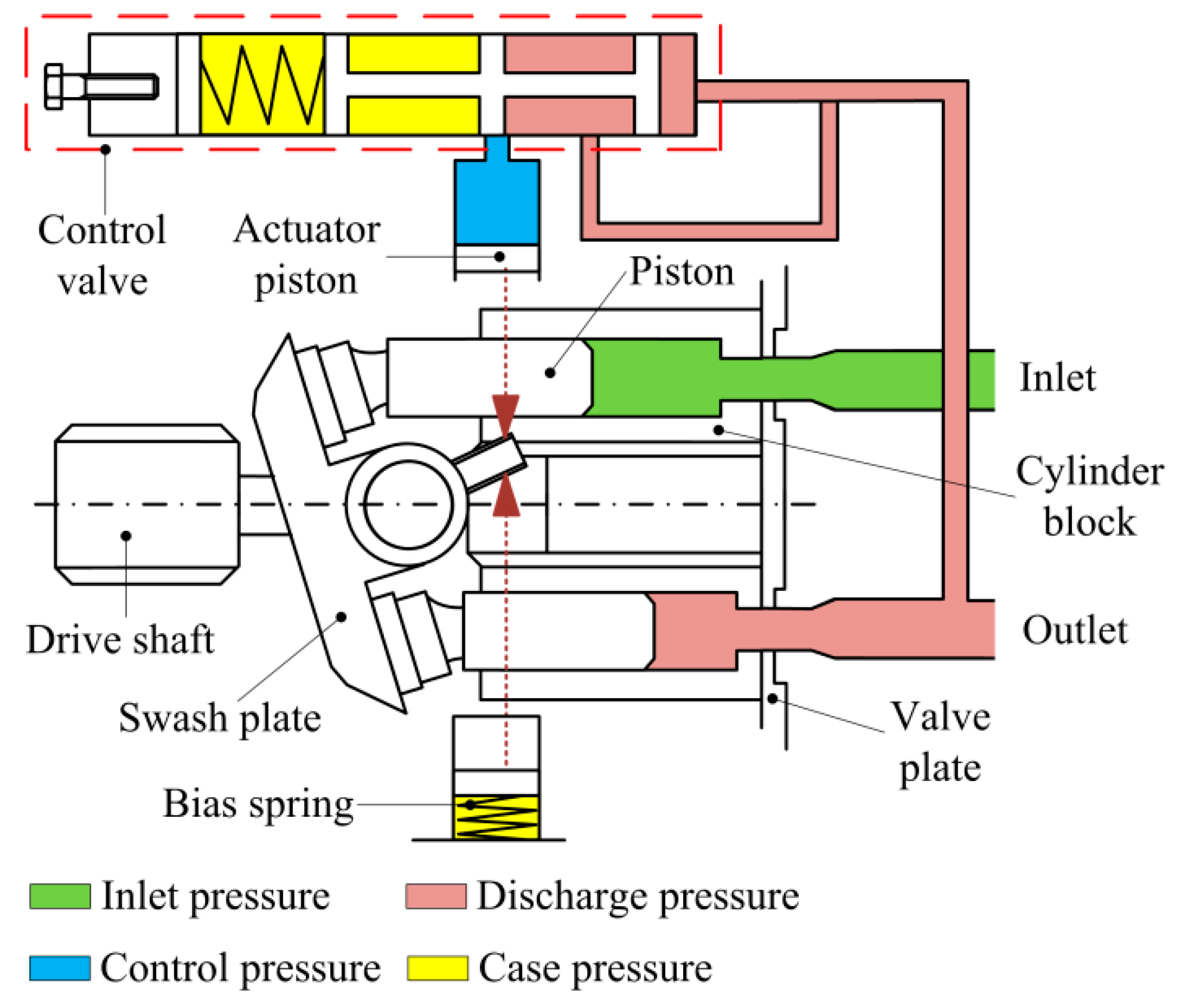
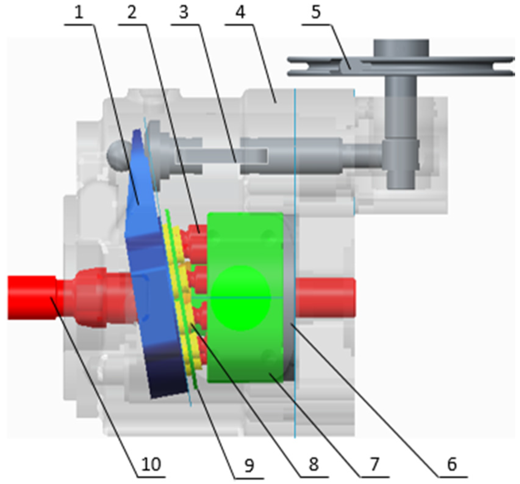
A schematic diagram of a swash plate VDAPP with a constant power regulator is shown in Figure 1. Figure 2 represent hydraulic circuit of the constant power regulator system. The constant power regulator system consists of five parts, that is, a regulator assembly (A), a control cylinder assembly (B) which controls the angle of the swash plate, a counterbalance assembly (C), a swash plate (D), and a piston (E). As shown in Figure 3, the regulator assembly consists of a spool and sleeve. A flow area of the regulator system is determined by relative displacement between spool and sleeve. Figures 4 and 5 show the detailed structure of the control cylinder and counterbalance.
As shown in Figure 8, the swash plate is held in a certain swivel angle. In this area, the discharge pressure of the pump does not feed back into the control cylinder. This causes the swash plate to rotate in a maximum angular displacement. As a result, the pump can supply the maximum flow rate to a load system unless the discharge pressure of VDAPP is sufficiently increased to a certain level by a load. At the maximum flow rate section shown in Figure 9, the discharge flow rate cannot be feed into the control cylinder because the spool blocks the path of the sleeve.
The increased load pressure makes the spool move, and pilot flow rate is supplied into the control cylinder [7–9]. Then, the swivel angle is decreased as shown in Figure 10. By the kinematic constraints of the piston, the sleeve acts as a reaction force to the swivel torque. During this time, the swivel angle of the swash plate should be reduced gradually in order that the VDAPP can discharge the flow rate with constant power.
In the constant power area shown in Figure 11, the spool is moved by the pilot pressure which is equal to load pressure, and the spool displacement makes the flow path to the control cylinder open. Then, the flow is supplied to the control cylinder. Therefore, the swivel angle is decreased, and the discharge flow rate of the pump is reduced. When the swivel angle is decreased, the sleeve reduces or blocks the flow to the control cylinder by the movement of the counterbalance piston. Therefore, the displacement of the control cylinder is adjusted according to the load variation. Consequently, the increase of the load pressure decreases the discharge flow rate of VDAPP, and that makes output power of VDAPP constant because the output power of VDAPP is determined by the product of load pressure and discharge flow rate.
When the load pressure reaches a limit, the VDAPP makes the discharge flow zero by setting the swivel angle of swash plate vertically, as shown in Figure 12. In this section, the discharge flow rate from VDAPP is rapidly decreased because the sleeve stroke is blocked by the kinematic constraint of the regulator. Then, the VDAPP sets the swash plate vertically and cuts off the discharge flow rate, as shown in Figure 13.
As previously described, these characteristics of the pump-regulator assembly are determined by the interaction of the spool and sleeve. The pilot pressure generated by the load pressure of the system affects the spool.
where is flow coefficient of orifice, and represent the orifice areas, is discharge pressure of the hydraulic pump, and is density of working fluid.
The displacement of the control cylinder, in (4), is determined by the resultant force on the swash plate as shown in Figure 15. The various forces are expressed in the form of a complex nonlinear model. In this study, in order to derive more accurate results, the VDAPP was also implemented using AMESim software.
A VDAPP with a mechanical regulator system was established using AMESim simulation software, which allows a very accurate implementation of the response of a nonlinear system. In the field of hydraulic component design, AMESim is widely used to optimization and performance improvement as a review of the actual system [5]. Figure 16 shows an AMESim diagram for the analysis of the system performance of an MPR system that consists of nine pistons.
The maximum swivel angle was set to 16°, which is the same as in the real component, and the exclusion volume was set to 11.6 cm3/rev. All parameters of the VDAPP are the actual design values used in the experimental equipment. The experimental equipment was modeled by considering the nonlinear behavior of the MPR pump system.
If the pump is composed of an odd number of pistons, the number of discharging pistons is determined by the rotation angle of the piston, which located at regular intervals on the plate as follows [11]:
Figure 17 shows the simulation result when the pump is driven at 4500 rpm under no-load condition. The discharge flow rate is the sum of the flow rate of each piston. The pulsation in flow rate is observed in simulation result as shown in Figure 17. This simulation results also show that the average value of the discharge flow rate 49.8 L/min is less than the theoretical one 52 L/min because the internal leakage through the gap between the piston and cylinder block is considered in computer simulation.
Figure 19 shows the hydraulic circuit of test rig for VDAPP. The angular velocity of the electric motor is regulated as 4500 rpm, and the load pressure is adjusted by adjustable relief valve which installed in the discharge line of the VDAPP. The discharge pressure is slowly increased during 45 seconds. The load pressure, the discharge flow rate, and the angular velocity and the torque of the electric motor are acquired by data acquisition board in real time.
In this study, the constant power mechanical regulator system with variable displacement axial piston pump is considered. The constant power mechanical regulator with VDAPP has a problem of pulsation in the discharge flow rate at the cut-off area. In order to solve the problem, the internal behavior of the constant power regulator with VDAPP is analyzed by modeling the system using the AMESim software. The theoretical analysis of constant power regulator is induced for precise modeling, and the internal dynamics of un-measurable components are studied. The validation of the simulation model is confirmed by comparing the simulation results with the experimental output of the real system. By analyzing the dynamics of the unmeasurable internal components, it is found that the irregular discharge flow rate is caused by the discontinuous shape at the edge of the counterbalance piston. Therefore, we proposed the rounded shape for the edge of the counterbalance piston. The effect of the redesigned shape is implemented by AMESim simulation, and the validation is verified by computer simulation. The future work is experimental confirmation of the redesigned shape.

The Positive Displacement Pump Training Course has been developed to assist in Pump Maintenance and Operation. It covers both Reciprocating Pump Working as well as Rotary Pump Working Principles. Explicit Graphics and Animation give an in-depth understanding on working details of various pump types like Screw Pump Working and Gear Pump Working. The training course, designed with extensive Graphics and Animation, gives a virtual Detailed Practical exposure on a large number of Positive Displacement Pumps Types like Gear, Lobe, Vane, Screw, Peristaltic, Metering, Power, Diaphragm, Piston, Beam, Hydraulic, etc. with a detailed Pump Classification. The course also includes an Interactive, Graphically supported Troubleshooting Guide.
The Positive Displacement Pump Training Course (Reciprocating Pump Training and Rotary Pump Training) covers both the Rotary Pump Working and Reciprocating Pump Working. The Training course covers a large range of Pump types like Screw, Gear, Lobe, Vane, Peristaltic, Metering, Power, Diaphragm, Axial Piston Pump, Swash Plate, Wobble Plate Piston, Bent Axis, Radial Piston Pump, Variable Displacement, Sucker Rod, Hydraulic, Beam, etc.
The primary focus on Pump Graphic / Positive Displacement Pump Animation (Reciprocating Pump Animation and Rotary Pump Animation) in the CBT helps in very clearly understanding the Pump Working Principle. The Working principles of various pumps like Screw Pump Working and Working of Gear Pumps are easily understood by the intricate Pump Animations.
The Positive Displacement Pump Training Program has a dedicated module to assist Rotary and Reciprocating Pump Troubleshooting. Animated Cut-Sections clearly explains Rotary and Reciprocating Pump Working and gives a Deep Insight into Pump Operation and how Pumps Work.

Fig. 1 shows the structure of a pressure compensated axial-piston pump. It can be broadly divided into six parts, namely, the drive-shaft/cylinder assembly, the piston/slipper-shoe units, the swash plate, the control valve, the control actuator and the related accessories including the pump-housing and valve-plate. During operation, an external motor rotates the drive-shaft/cylinder assembly (at speed ω), and hence the piston (area Ap, mass mp) and slipper-shoe units. Pressing against the inclined plate, the rotating drive-shaft motion is transformed into a translational piston motion parallel to the shaft. The inclinational angle φ of the swash plate, which is adjusted for the pump flow rate, can be angularly positioned by manipulating the control actuator (area Aa, mass ma) against a bias spring (stiffness kb) positioned parallel to the shaft axis at a distance l. However, nonlinear influences, such as the changing volume of chambers, the orifices and the compressible oil, complicate the pump dynamic model immensely. There are obvious FSIs in the pump, where the motions of the rigid bodies compress the fluid, and then that fluid pressure fluctuation causes the rigid bodies to vibrate in turn. The transfer methods of mechanical vibration and fluid pressure force in conventional piston pump models are mostly unidirectional and separated. Based on the synthesized description of the structure of the pump, the block diagram of the pump is summarized in Fig. 2.
(a) Full FSI model; (b) Non FSI model. Av: the cross-sectional area of control valve spool; Fpi: the force from the swash plate to the ith piston; Fpa: the force from the swash plate to the control actuator; pa: the pressure in the control chamber 1; p2: the pressure in the control chamber 2; po: the pressure in the outlet chamber; Pi: the pressure in the ith piston chamber; q12: the flow rate between two control chambers; qpi: the flow rate of the ith piston; qv: the flow rate of control valve; V1, V2: the volume of the control chambers; wv: the control valve spool perimeter; xv: the control valve spool displacement; z0i: the piston displacement; z0a: the control actuator displacement
As shown in Fig. 2a, there are three main FSIs in the pump. The FSI-1 that contains the pistons and the variable piston chambers is the most complicated and important FIS in the pump. The velocity, displacement, and pressure of the pistons and chambers are different at any time. The flow fluctuation from the piston chamber can be divided into two parts. The first part is the kinematic flow fluctuation, which is due to the limited number of pistons and directly caused by their motions. The second part is the compressible flow fluctuation, which is caused by large alternating pressures in the valve plate. The FSI-2 contains the control actuator and the dynamic control chamber, whose main function is to adjust the swash plate at a suitable angle to meet the preset discharge pressure. Hence, the dynamic motion of the swash plate is greatly influenced by the FSI-2. The FSI-3, unit of the moving control valve spool, its variable chamber and variable opening, mainly affect the flow rate to the outlet chamber and the discharge pressure pulsation. Besides, the FSI-3 indirectly affects the pressure of the control actuator chamber and the vibration of the swash plate. The pistons, the control actuator, and the control valve, which are the key components of the three main FSIs, are simplified and their high-order dynamics are neglected in the non FSI model in Fig. 2b.
The relative positions of the key components of FSI-1 are shown in Fig. 3. It can be seen that X0Y0Z0 is the space-fixed reference frame assigned at the center of the pump, with its Z0-axis pointing along the central axis of the drive shaft. The X0-axis is vertical to the drive shaft and through the top dead center of the piston. The reference frame X4Y4Z4 (with its X4 and Z4-axes pointing along the top-dead center and vertical to the motion plane of the piston spherical joints) is assigned at the intersection O4 of the shaft and the motion plane of the piston spherical joints. Hence, X4Y4Z4 coincides with X0Y0Z0 when the inclinational angle φ is zero, and the synthesized transformation matrix is \({}_4^0T\) where 0P is the final position of the ith piston transformed from 4P.
(a) Location of the coordinate systems; (b) Movement sche-matic of slipper shoes and pistons. BDC: bottom dead center; TDC: top dead center; ele: the eccentricity between the drive shaft and the swash plate rotation axis; els: the eccentricity between the center of the spherical joint and the swash plate rotation axis
As a key mechanism of FISs, the torque on the swash plate can be transferred from the forces on the pistons at X4Y4Z4 (with the synthesized transformation matrix \({}_4^5T\)). The reference frame X5Y5Z5 is assigned at the center O5, with its Y5-axis coinciding with the rotational axis of the swash plate, and X5-axis and Z5-axis parallel and vertical to the plane of the swash plate. 5P is defined as the position of the piston at X5Y5Z5. Hence, the lever arm length of each piston is equal to the coordinate value at the X5-axis of 5P. The synthesized transformation matrix \({}_4^5T\) and the coordinate values of 5P are given as
The dynamic FSIs in the pump are modeled as a system with lumped parameter nonlinear components of different energy subsystems. The swash plate angle and the outlet chamber pressure interact with each other through the three FSIs.
The position of the swash plate is defined by the bias actuator, the control actuator, the slippers, and the pistons, which are known as FSI-1 and FSI-2. The inclination φ of the swash-plate (inertia Js) relative to the pump case is governed by the torques, T0, Ta, and Tp, contributed by the pre-tightening force of the bias spring, control actuator, and the forces of the piston/slipper units, respectively. The dynamic equation of the swash plate rotation (with damping coefficient bs) about the Y5-axis is described by
where x5a is the position of the control actuator at the X5-axis of the reference frame X5Y5Z5, which is also identified as the moment arm of the control actuator pressure force relative to the rotation axis of the swash plate (Y5-axis). Once the average angle of the swash plate is stable, the average sum torque Tp from the pistons is constant. The actuator torque Ta is designed to counteract the piston torque Tp to balance the swash plate. Hence, the longer the moment arm, the less is the pressure force Fa of the control actuator. It means that a smaller area Aa or a lower actuator pressure pa is needed. However, a longer moment arm may increase the bulk and weight of the pump.
The FSI-1 contains the motion of the pistons, the changing volumes and the pressure of the piston chambers. The swash plate and the outlet chamber are connected by FSI-1. The pistons move along the Z0-axis following the oscillation of the swash plate. The moving pistons make the piston chambers take oil from the inlet chamber and discharge it to the outlet chamber. Conversely, the changing pressures of the piston chambers result in forces on the pistons, which cause the high frequency disturbed vibration of the swash plate.
where m is the mass of one piston, bi is the damping coefficient of the ith piston, A is the pressure area of one piston, pi is the pressure of the ith piston chamber, and fi is the sliding friction between the piston and the cylinder block. As a disturbing force, the friction fi is much lower than the pressure force on the piston and can be ignored. Therefore, the value of the friction in the simulation models can be set to zero. Hence, the total torque Tp on the swash plate of the pistons can be derived as
where x5i is the position of the ith piston at the X5-axis of the reference frame X5Y5Z5, which is also identified as the moment arm of one slipper shoe relative to the rotation axis of the swash plate (Y5-axis).
where Tpa is one part of the Tp, which does not contain the second derivative of φ. The dynamic differential equation of the swash plate and piston oscillatory mechanism is modified from Eq. (5) as
where qli is the piston leakage flow, qii is the flow from the inlet port and qoi is the flow to the discharge port. The leakage flow consists of three main parts: the first is the leakage passage between pistons and the cylinder, the second that between the cylinder and the valve plate, and the third that between the slipper shoes and the swash plate.
The control actuator connects the control valve to the swash plate throughout FSI-2. The FSI-2 contains the motion of the control actuator, the changing volumes, and the pressure of the control actuator chamber 1. Similarly to the pistons, the control actuator moves along the Z0-axis following the oscillation of the swash plate. The moving actuator piston makes the control chamber 1 charge/discharge oil from the control chamber 2. Conversely, the changing pressure of the chamber results in a changing force on the control actuator, which causes the high frequency disturbed vibration of the swash plate.
where ma is the mass of the control actuator, ba is the damping coefficient, Aa is the pressure area, pa is the chamber pressure, fa is the sliding friction, and z0a is the control actuator displacement. Hence, the torque Ta on the swash plate of the control actuator can also be derived as
where Taa is one part of the Ta, which does not contain the second derivative of φ. Ja is defined as the equivalent moment of inertia (rotational inertia) to the swash plate rotary axis (Y5-axis) of the control actuator. As a disturbing force, the friction fa is much lower than the pressure force on the control actuator and can be ignored. Therefore, the value of the friction in the simulation models was set to zero.
The dynamics of the control valve mechanism contain complex FSIs, FSI-3, which connect the outlet chamber to the control chamber 2 as shown in Fig. 4. The control valve turns the discharge pressure to the displacement of the spool, which causes the flow rate through the valve port and the outlet volume to change. The pressure of the chamber V2 changes with the oil flow, and leads to a pressure difference with the chamber V1. The feedback loop driven by the control valve and the bias actuator keeps the discharge pressure at a certain value changing with the load. The orifice between the control valve and the bias actuator can increase the damping of the bias actuator and stabilize the motion of the swash plate.
Parker PVplus axial piston pump with variable displacement has been designed and optimized for demanding use in heavy duty industrial and marine applications. With pressure ratings of up to 420 bar and high-speed ratings this open circuit, swashplate principle axial piston pump provides high productivity and power density to its users. Beside its robustness and exceptionally long service life, PVplus is also characterized by a very high conversion flexibility. As a standard every PVplus comes with an integrated pre-compression volume which ensures low ripple operation and reduced noise emissions. A wide range of displacements and control options allows for a wide range of applications.

All the controls used in the Series 02 are based on a load-independent control mechanism. No matter which control is used: identical commands always result in the same response in the machine. The sensitive and precise machine control makes work easier and increases productivity. Various customer system options for mechanical, hydraulic and electric input solutions are available. Further special regulating features like torque control and pressure cut-off are also available. The reliable control of the pump can easily be integrated into any kind of vehicle management control system.


 8613371530291