
unidirectional hydraulic pump factory
It happens often that our customers are not clear about the difference between reversible pumps and unidirectional pumps. This is a legitimate doubt due to the fact that, in the industry, there is no shared nomenclature because each company follows its own classification.
At Vivoil, for example, we have chosen the terms “reversible” and “unidirectional,” but other manufacturers use “bidirectional” or “bisense” to refer to what, for us, is a pump that rotates both clockwise and counterclockwise.
Reversible pumps are so called because they can rotate-once installed-both clockwise and counterclockwise, without having to make any modifications. As shown in the drawing below:
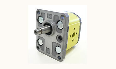
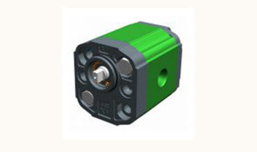
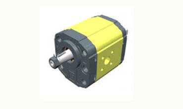
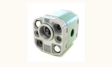
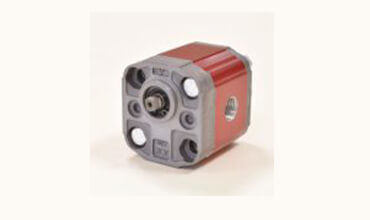
Vivoilunidirectional pumpscan only rotate in one direction: clockwise or counterclockwise. However, depending on your needs, you can change their direction of rotation and turn a pump that was born to turn only clockwise into one that turns only counterclockwise and vice versa, easily, because you do not need to add any components.
The flange of this model has a diameter of 36,5 mm. The rotation verse of the pump is clockwise or counterclockwise and you can reverse it without having to add any components* to optimize storage space and adapt the product to your needs. Please refer to page 23 of this catalogue for instructions on changing the rotation verse.
Vivolo manufactures high-end hydraulic components, essential for the operation of various types of machinery: agricultural, industrial, automotive and earth-moving. Their products can be customized in their technical features, starting from small quantities.
There are typically three types of hydraulic pump constructions found in mobile hydraulic applications. These include gear, piston, and vane; however, there are also clutch pumps, dump pumps, and pumps for refuse vehicles such as dry valve pumps and Muncie Power Products’ Live PakTM.
The hydraulic pump is the component of the hydraulic system that takes mechanical energy and converts it into fluid energy in the form of oil flow. This mechanical energy is taken from what is called the prime mover (a turning force) such as the power take-off or directly from the truck engine.
With each hydraulic pump, the pump will be of either a uni-rotational or bi-rotational design. As its name implies, a uni-rotational pump is designed to operate in one direction of shaft rotation. On the other hand, a bi-rotational pump has the ability to operate in either direction.
For truck-mounted hydraulic systems, the most common design in use is the gear pump. This design is characterized as having fewer moving parts, being easy to service, more tolerant of contamination than other designs and relatively inexpensive. Gear pumps are fixed displacement, also called positive displacement, pumps. This means the same volume of flow is produced with each rotation of the pump’s shaft. Gear pumps are rated in terms of the pump’s maximum pressure rating, cubic inch displacement and maximum input speed limitation.
Generally, gear pumps are used in open center hydraulic systems. Gear pumps trap oil in the areas between the teeth of the pump’s two gears and the body of the pump, transport it around the circumference of the gear cavity and then force it through the outlet port as the gears mesh. Behind the brass alloy thrust plates, or wear plates, a small amount of pressurized oil pushes the plates tightly against the gear ends to improve pump efficiency.
A cylinder block containing pistons that move in and out is housed within a piston pump. It’s the movement of these pistons that draw oil from the supply port and then force it through the outlet. The angle of the swash plate, which the slipper end of the piston rides against, determines the length of the piston’s stroke. While the swash plate remains stationary, the cylinder block, encompassing the pistons, rotates with the pump’s input shaft. The pump displacement is then determined by the total volume of the pump’s cylinders. Fixed and variable displacement designs are both available.
With a fixed displacement piston pump, the swash plate is nonadjustable. Its proportional output flow to input shaft speed is like that of a gear pump and like a gear pump, the fixed displacement piston pump is used within open center hydraulic systems.
As previously mentioned, piston pumps are also used within applications like snow and ice control where it may be desirable to vary system flow without varying engine speed. This is where the variable displacement piston pump comes into play – when the hydraulic flow requirements will vary based on operating conditions. Unlike the fixed displacement design, the swash plate is not fixed and its angle can be adjusted by a pressure signal from the directional valve via a compensator.
Vane pumps were, at one time, commonly used on utility vehicles such as aerial buckets and ladders. Today, the vane pump is not commonly found on these mobile (truck-mounted) hydraulic systems as gear pumps are more widely accepted and available.
Within a vane pump, as the input shaft rotates it causes oil to be picked up between the vanes of the pump which is then transported to the pump’s outlet side. This is similar to how gear pumps work, but there is one set of vanes – versus a pair of gears – on a rotating cartridge in the pump housing. As the area between the vanes decreases on the outlet side and increases on the inlet side of the pump, oil is drawn in through the supply port and expelled through the outlet as the vane cartridge rotates due to the change in area.
Input shaft rotates, causing oil to be picked up between the vanes of the pump which is then transported to pump outlet side as area between vanes decreases on outlet side and increases on inlet side to draw oil through supply port and expel though outlet as vane cartridge rotates
A clutch pump is a small displacement gear pump equipped with a belt-driven, electromagnetic clutch, much like that found on a car’s air conditioner compressor. It is engaged when the operator turns on a switch inside the truck cab. Clutch pumps are frequently used where a transmission power take-off aperture is not provided or is not easily accessible. Common applications include aerial bucket trucks, wreckers and hay spikes. As a general rule clutch pumps cannot be used where pump output flows are in excess of 15 GPM as the engine drive belt is subject to slipping under higher loads.
What separates this pump from the traditional gear pump is its built-in pressure relief assembly and an integral three-position, three-way directional control valve. The dump pump is unsuited for continuous-duty applications because of its narrow, internal paths and the subsequent likelihood of excessive heat generation.
Dump pumps are often direct mounted to the power take-off; however, it is vital that the direct-coupled pumps be rigidly supported with an installer-supplied bracket to the transmission case with the pump’s weight at 70 lbs. With a dump pump, either a two- or three-line installation must be selected (two-line and three-line refer to the number of hoses used to plumb the pump); however, a dump pump can easily be converted from a two- to three-line installation. This is accomplished by inserting an inexpensive sleeve into the pump’s inlet port and uncapping the return port.
Many dump bodies can function adequately with a two-line installation if not left operating too long in neutral. When left operating in neutral for too long however, the most common dump pump failure occurs due to high temperatures. To prevent this failure, a three-line installation can be selected – which also provides additional benefits.
Pumps for refuse equipment include both dry valve and Live Pak pumps. Both conserve fuel while in the OFF mode, but have the ability to provide full flow when work is required. While both have designs based on that of standard gear pumps, the dry valve and Like Pak pumps incorporate additional, special valving.
Primarily used on refuse equipment, dry valve pumps are large displacement, front crankshaft-driven pumps. The dry valve pump encompasses a plunger-type valve in the pump inlet port. This special plunger-type valve restricts flow in the OFF mode and allows full flow in the ON mode. As a result, the horsepower draw is lowered, which saves fuel when the hydraulic system is not in use.
In the closed position, the dry valve allows just enough oil to pass through to maintain lubrication of the pump. This oil is then returned to the reservoir through a bleed valve and small return line. A bleed valve that is fully functioning is critical to the life of this type of pump, as pump failure induced by cavitation will result if the bleed valve becomes clogged by contaminates. Muncie Power Products also offer a butterfly-style dry valve, which eliminates the bleed valve requirement and allows for improved system efficiency.
It’s important to note that with the dry valve, wear plates and shaft seals differ from standard gear pumps. Trying to fit a standard gear pump to a dry valve likely will result in premature pump failure.
Encompasses plunger-type valve in the pump inlet port restricting flow in OFF mode, but allows full flow in ON mode lowering horsepower draw to save fuel when not in use
Wear plates and shaft seals differ from standard gear pumps – trying to fit standard gear pump to dry valve likely will result in premature pump failure
Live Pak pumps are also primarily used on refuse equipment and are engine crankshaft driven; however, the inlet on a Live Pak pump is not outfitted with a shut-off valve. With a Live Pak pump, the outlet incorporates a flow limiting valve. This is called a Live Pak valve. The valve acts as an unloading valve in OFF mode and a flow limiting valve in the ON mode. As a result, the hydraulic system speed is limited to keep within safe operating parameters.
Outlet incorporates flow limiting valve called Live Pak valve – acts as an unloading valve in OFF mode and flow limiting valve in ON mode restricting hydraulic system speed to keep within safe operating parameters
Hydraulic pump and power unit in high pressure from 700 to 4000 bar designed and produced by FPT – Fluid Power Technology to adapt to the multiple needs of customers. They are available in 4 different motor configurations: three phase electric or single phase electric, gas engine and air / pneumatic motor.
Hydraulic pumps are equipped with piston pumps with different flow rates available in the single stage version model FPT2 and in the double stage model models FPT 1-5 and 9. It is possible to mount a wide range of manual, electric or pneumatic valves for cylinders or applications simple or double effect. In the standard configuration there are 10 liter tanks up to 60 liters and a very wide range of accessories including transport cages, pressure gauges, quick couplings, heat exchangers, filters, unidirectional valves and many others. The FPT Hydraulic pump and power unit are made with a high constructive flexibility to meet the most varied customer needs and can be used to drive one or more hydraulic cylinders of any tonnage or single or double acting actuators. FPT also specializes in the design and production of cusotm hydraulic pumps manufactured according to specific customer requests. When standard production fails to meet customer requirements FPT is able to design and produce hydraulic power packs designed with operating pressure from 350 bar up to 4000 bar, having extremely compact tanks of 2 or 5 liters up to large tanks for driving multiple cylinders up to 400 or 500 liters. The pumps can be axial or radial, single-stage, dual-stage, combined and have capacities suitable for the customer’s application. The special high pressure pumps and units can be equipped with a three-phase or single-phase electric motor, 110V, 220V, 480V, 50hz or 60hz, or with a pneumatic or petrol engine. With pump motor units having the installed power required by the customer.
The base symbol for the hydraulic pump (Figure 1) is actually quite simple. It starts with the standard circle and a directional arrow pointing out one end from within that circle. The solid-filled triangle makes this a hydraulic pump while pneumatic pumps (and most pneumatic symbols) are outlines only. There exist no other options for this particular pump symbol, which can be accurately described as a fixed displacement, unidirectional hydraulic pump.
It’s rare to see a pump in any orientation but North when reading schematics, and they are often paired below to a line terminating into the reservoir symbol, which I show just once. If multiple components such as filters, ball valves, accessories or even other pumps are used, the tank line can be widened as needed. Other designers prefer to show every tank line terminate into the same small symbol, while others will place a tank symbol right at every component requiring it, just is done in electrics with the ground symbol.
My favorite symbol to express the pressure compensated pump is the smaller of the two symbols in Figure 2. This is a slightly more detailed example of the symbol I depicted in Hydraulic Symbology 101, and I’ve added color to help with the explanation. Don’t worry about the scary looking object to the right, we’ll get to that shortly.
For this particular symbol of the pressure compensated pump, the shaft sticks out to the right, which can be attached to the square of a combustion engine prime mover symbol or the circular symbol of an electric motor. The semicircular arrow shows us the shaft rotates clockwise, or to the right since rotation direction is always observed from the vantage point of the shaft end.
The variable arrow bisects the pump symbol and of course tells us the pump is adjustable displacement. The method of displacement control is defined by the compound symbol attached to the pump’s left. Under the long rectangle is a spring with a variability arrow, which represents the pressure compensator spring, itself semienclosed and attached to the bottom of the pump’s variable arrow. Opposite the spring is a triangular input for pilot pressure, and this juxtaposition is intentional.
The orange pilot signal is taken directly from the red system pressure line exiting the pump, with the dashed orange line confirming it is indeed pilot energy. The spring setting fights with pilot pressure to infinitely and smoothly adjust the flow rate to match downstream pressure drop equal to the compensator setting. For example, if the setting is 3,000 psi, any downstream combination of load and flow-related pressure below 3,000 psi will see the spring maintain full displacement of the swashplate, producing full pump flow.
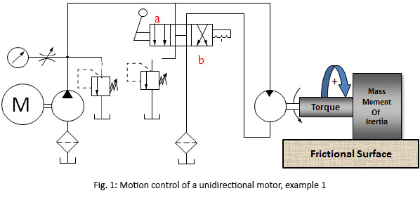
Moving along to the scary looking thing on the right, we have here the detailed breakdown of the variable displacement, pressure compensated, load-sensing, unidirectional hydraulic pump. You’ve likely seen this symbol before because the manufacturers prefer to show this level of detail, especially to differentiate advanced controls options like remoted compensation or horsepower control. This “load-sensing pump” will make sense to you shortly. I’ll warn that it will take some time and effort to understand this symbol as you methodically work through the rest of this article.
Starting with the pump (a), it has the diagonal variability arrow bisecting the circle and is attached to the rod ends of two cylinders. Cylinder (b) is the bias piston meant to force the pump to full displacement whenever possible, a task made easier by a spring pushing the piston forward. Some pumps make do with only a strong spring, but this example is balanced with pilot energy. Affixed on the right is a tiny object with a variable arrow, which can be adjusted to move left or right within the cylinder. Not all pumps have this additional component, which is the minimum volume stop, preventing the bias piston from retracting fully, which subsequently prevents fully standby of the pump.
If you’re familiar with cylinder symbols, you’ll see that (c) also looks like a single acting cylinder with a stroke adjustor at the cap side. This is the control piston, which will always be a larger bore diameter than the bias piston. The control piston’s stroke adjustment is called the maximum volume stop and is used to modify the maximum displacement of the pump, convenient when you need a displacement between the two sizes available for the chosen pump. The two “cylinders” are attached by their rods to each other, and as one extends the other must retract and vice versa, and I’ll explain shortly why and how their battle develops.
Because all load sensing pumps must be pressure compensated, I’ll start with (d), which is the pressure compensator. Although it looks different, it is essentially a relief valve governing the control piston (c). It’s shown in its neutral condition, where it bleeds the chamber of the control piston (c) through orifice (e), orifice (f), and also through the other compensator (g) where it can choose any flow path directly to tank. Regardless of its flow path, pilot energy inside the control piston (c) is zero, so it loses the battle with the bias piston (b) and the pump is on full displacement pump at its highest rate.
The variable orifice at (j) could be any flow control, lever valve or proportional valve used to adjust flow (which creates backpressure when reduced) in the red system pressure line starting at the pump. You can see the node just after the pump outlet that combines system pressure with pilot lines supplying the bias piston and both compensators. Let’s first take the load sense compensator (g) out of the picture and describe the pressure compensator (d) and what occurs during operation.
When the pump fires up, and assuming all downstream directional valves are closed, the spring inside the bias piston (b) fully strokes the pump to max displacement. This immediately creates pressure in the work and pilot lines as fluid fills the plumbing with no exit strategy, and this rise in pressure at the pilot line at (d) forces the pressure compensator to shift to the right. The second pilot line attached to the top of compensator (d) allows pilot energy to enter through line (i) where it fills the control piston (c) rapidly. Because the control piston is larger bore than the bias piston, it wins the fight and moves the pump’s variable arrow to reduce displacement until the only flow is what is required to overcome leakage. The pump is on “standby.”
Now when a downstream directional valve is opened, a flow path is created that drops system pressure to below the setting of the (d) compensator, and it immediately succumbs to spring pressure and snaps back to near its neutral setting, opening the drain lines once again to tank. The orifices (e) and (f) dampen the motion of the compensator, preventing rapid oscillations, but the orifice also prevents pressure spikes into the pump’s case. They also ensure that pressure doesn’t decay from the control piston (c) when system pressure degrades rapidly for fractions of a second. Flow from the pump will be balanced by the opposing bias and control pistons to match downstream pressure drop at exactly the pressure compensator setting.
Finally, we look at the operation of the load sense compensator (g) shown on top. It also receives a pilot signal directly from the pump outlet, but you’ll see that it also gets a competing signal from the work line after the metering orifice. The pressure signal at (g) compares the combined effort of the spring value and the load-sense pilot signal just before (h). The setting of the pressure compensator (d) is much higher than the setting of the load sense compensator (g), which is set to create reasonable pressure drop across (j). If the (d) compensator is set to 3,000 psi, it’ll only see this pressure on standby or max load pressure, while the (g) compensator might be set to 300 psi, where it measures pressure drop across (j) valve.
Typically a load sense circuit will have multiple orifices in a load sense network all feeding back a pilot signal to the load sense compensator (g), where it picks the highest pressure signal and meters the pump’s flow to match that pressure differential and provides just enough flow to satisfy the desired flow rate at the desired work pressure plus the pressure of the load sense compensator’s spring value. For example, if load pressure is 1,000 psi, the pump will hold pressure at 1,300 psi, providing the extra 300 psi just to create flow across the metering valve (j).
This symbol shows you that no matter the initial feeling of complexity, breaking down any schematic thoughtfully reveals its purpose of design. I fell in love with hydraulics when I learned about the load sensing concept. That just using columns of fluid pressure to create an efficient supply and demand scenario to satisfy many downstream actuators with essentially the exact flow and pressure they need for the job, and little more, I found exhilarating.
The symbols for hydraulic motors, especially in their simpler forms, are very similar to those of hydraulic pumps. If you haven’t already had the chance, see my article on pumps symbols here first. The directional arrow that points inward to accept fluid power energy is the primary difference between pump and motor symbols, and in Figure 1 you can see the simple fixed displacement, unidirectional hydraulic motor.
The second symbol stands for the variable displacement bi-rotational motor. The dark triangle depicting the direction of hydraulic energy is now diametrically opposed to indicate the motor takes fluid from both ports. If it’s not plain enough already, the shaft has bidirectional rotation arrows bent around the shaft as well. You will also notice both ports are now open to flow rather than one that terminates at the tank as the first symbol. Finally, the tell-tale variable arrow dissects the circle, showing us the motor has a variable displacement, although telling us nothing of how that might occur.
The final symbol of Figure 1 is just like the last, save for two slight differences. The dark flow triangles are stacked atop each other and in opposing directions. This configuration represents a unit capable of both pumping and absorbing hydraulic energy, or more succinctly, the variable displacement, bi-rotational pump-motor. Used in few locations other than a drive application, such as the clever hydraulic hybrid applications for dump trucks or loaders, where stopping energy can be fed back into the system and stored in an accumulator.
Motor controls, aside from hydrostatic drives, are not usually overly complicated. The variable displacement, bi-rotational hydraulic motor shown on the left in Figure 2 has everything the earlier one did save the case drain line. Being a simplified symbol, as most fluid power symbols are, it gives you basic details on what it does but doesn’t provide the scope of performance, the method of construction or dimensional envelope. The apparent mess of lines and shapes to the right does, in fact, break down the method of operation, at the very least.
When a pilot valve somewhere upstream of (x) is activated, fluid enters the pilot chamber of the 3/2 valve (g), where it shifts to provide pilot energy sourced from the shuttle valve (c) to the bias piston. The bias piston now shifts fully, reducing the swashplate angle to reduce flow. Just how low the displacement goes is dictated by the tiny stroke limiter (e), which is just an adjustment screw that prevents the swashplate from reducing its angle further. The orifice at (f) is used to dampen the actions of the pilot energy working to move the bias piston. Without this orifice, the pump may shift too quickly or be susceptible to work pressure fluctuations coming from ports (a) or (b).
The standard hydraulic cylinder depicted way back in Hydraulic Symbology 102 is as clean and pure as one can ask, but you’d be surprised at the number of ways a cylinder can be drawn (and therefore constructed). Where possible in these examples, I’ve made a wide piston rather than the single line in previous examples, and also shown the rod as a long rectangle as well. For some of these examples, it is required to make sense of the symbol, so I used it across the board for the purpose of consistency.
The Spring Retract Cylinder is another that takes little to decode. It starts by looking much like a regular cylinder symbol, but now with a giant spring placed in the annular (rod side) area of the cylinder. Imagine now that pressure is applied to the cap side and the piston starts to extend. As it does, the spring compresses in an attempt to once again retract the cylinder without the help of rod side hydraulic energy. When pressure is relieved from the cap side, the cylinder retracts using the compressed energy stored within the spring.
A ram is a hydraulic cylinder with one fluid port on a tube that is stuffed with a rod. The rod is typically a large diameter relative to the body because the base of the rod also performs as the piston. So if your ram has a 4-in. rod, then your ram has a 4-in. piston. The port can be drawn nearly anywhere on a ram because fluid coming in the side will still extend the cylinder, as fluid pressurizing the rod radially has no effect on it.
The series comprises of: Vivolo XV0P / XP 0 series unidirectional pumps; Vivolo XV0R / XR0 series reversible pumps; Vivolo XV0U / XU0 series unidirectional motors and Vivolo XV0M / XM0 series reversible motors.


 8613371530291