unidirectional hydraulic pump free sample

The volumetric efficiency (internal leakage) of hydraulic pumps will increase with age. Consequently, to prevent unnecessary downtime it is vital to check the efficiency of hydraulic pumps on a routine schedule. The test kit needed to perform the test must be relatively easy to install, safe, and accurate. A flow meter test kit is ideal for testing hydraulic pumps without removing them from service. This portable test kit will give you the same result as testing your pump on a state-of-the-art test bench at a fraction of the cost.
The unit comes equipped with a load cell and pressure gauge which allows the user to load the pump in a safe manner while running tests. The variable area flowmeter on the unit provides a quick, visual flow indication on an easy-to-read linear scale to confirm that flow systems are operating properly. The flow meter on the unit offers enhanced reliability and minimal maintenance over the course of a long life expectancy. All items on the test kits are of the highest quality.
The unit comes complete with an adjustable load cell, glycerine-filled pressure gauge with rubber boot, and inline flow meter; ready to load-test your hydraulic pumps, motors, and other hydraulic components safely and accurately.

The rotation verse is clockwise or counterclockwise, and you can reverse it without adding any components, so you can optimize storage space and adapt the pump to your needs. In this catalogue from pages 18 to 29, you will find instructions for changing the rotation verse of our unidirectional pumps, divided by type.

We have devised a number of special solutions to make our hydraulic motors even more powerful and resistant: 11 optional extras that you can integrate into the Unidirectional Hydraulic Motors and Reversible Hydraulic Motors of the Vivoil range.
Thebearing support is an option for our hydraulic motors thatincreases resistance to radial and axial loads. It is useful in various sectors and applications, in the case of transmissions with pulleys, toothed wheels and fans and in general when objects with a high mass have to be rotated. In the following picture you can see the bearing support fixed to the hydraulic motor and in an exploded view.
The pressure relief valve is used tolimit the pressure on the hydraulic motor and thus protect the motor and other components from damage caused by pressure peaks. It controls the oil pressure, limiting it to the valve’s set value.
External drainage is an option for unidirectional hydraulic motors and serves to preserve the internal seals of the motor from high pressures. It is normally used in series motors or motors with a pressure relief.
This is a system comprising a motor with a proportional relief valve, a distributor to reverse the direction of rotation and an anti-cavitation valve. The fan drive variant of Vivoil hydraulic motors is used to connect the motor directly to a cooling fan, to control its speed and direction of rotation with the help of an electronic management system connected to sensors and/or the motor.
In fact, we recommend integrating it in unidirectional motors with drainage pressures up to 25 bar and in reversible motors for drainage pressures up to 25 bar.
The electric bypass valve is used to divert the flow of oil from the inlet directly to the engine exhaust. The valve is activated by an external electrical signal. It is normally used in air compressors and water pumps.

The ideal in hydraulic system designis to match overall efficiencies to the application performance expectation. This requires the designer to first match the motor, then the pump to a specific system performance expectation. Whether the requirement is to do something within a specific time frame, or in handling a given amount of load, the design of the entire system will change depending on the motor selected.
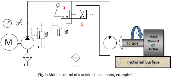
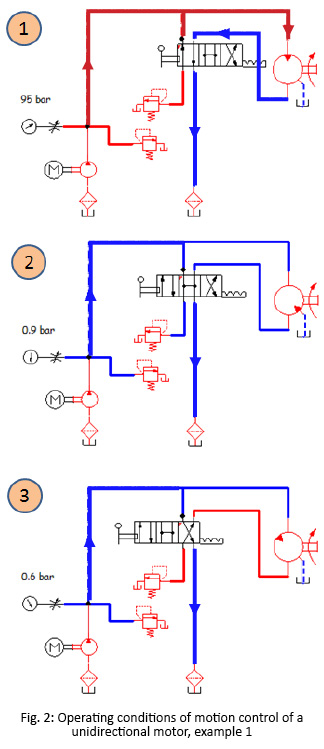
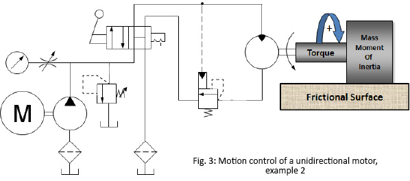
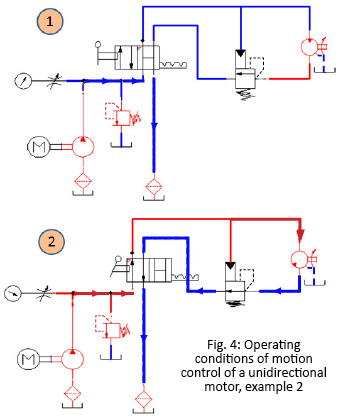
A hydraulic motor is a hydraulic actuator that, when properly connected into a hydraulic system, will produce a rotary actuation. This can be unidirectional or bidirectional depending on the system design. Motors are similar in design to pumps only where a pump takes a rotary actuation to move hydraulic fluid out of the unit, whereas a motor will take flow into itself and put out a rotaryactuation.
The motor selection comes first in the process because application design best practices require that you start with the load requirement, then work back to the prime mover—the pump that will put the fluid power into the motor selected to deliver the performance goal.
Starting torqueis the torque the motor can generate to turn a load when starting from a stop. In general, starting toque is the lowest torque rating of a hydraulic motor due to inefficiencies.
The rotationalspeedof the motor shaft is measured in units of rotations per minute (rpm). Motor speed is a function of hydraulic input flow and motor displacement.
Pressure is generated by resistance to hydraulic flow. The more resistance, the higher the pressure. Common measurement units are pounds per square inch (psi), kilo Pascal’s (kPa) or bar.
Common motor classes and typesGenerally, hydraulic motors are placed into one of two classifications: high speed, low torque (HSLT) or low speed, high torque (LSHT).
Gear motorscome in two varieties—the gerotor/geroller or orbital and external spur gear designs. Orbital styles are classified as LSHT motors; however, some do exist with the HSLT classification. They consist of a matched gear set enclosed in a housing. When hydraulic fluid is moved into the motor, it causes the gears to rotate. One of the gears is connected to the motor output shaft, which produces the motor’s rotary motion. Key features include:
Applications include mobile hydraulics, agricultural machinery to drive conveyor belts, dispersion plates, screw conveyors or fans. Their biggest drawback is that they have a higher noise level.
Vane motorsare typically classified as HSLT units. However, larger displacements will fall into the LSHT range. Hydraulic fluid enters the motor and is applied to a rectangular vane, which slides into and out of the center rotor. This center rotor is connected to the main output shaft. The fluid being applied to the vane causes the output shaft to rotate.
Parker’s vane motors feature a balanced design where the inlet and outlet ports of the motor are applied to sections of the vane cartridge that are 180° apart from each other to ensure that the hydraulic forces are always in balance inside the motor. Key features include:
In-line piston motorsare classified as HSLT. Hydraulic fluid enters the motor and is applied to a series of pistons inside a cylinder barrel. The pistons are pressed against a swash plate, which is at an angle. The pistons push against this angle, which causes the rotation of the swash plate that is mechanically connected to the output shaft of the motor. The swash plate can be a fixed or variable angle. Variable angle motors can have their displacements adjusted between a maximum and minimum setting. The command signals to change the displacement can be electrical, hydraulic or a combination of both.
Bent-axis piston motorsare classified as HSLT. They are similar to inline motors except that the piston barrel is at an angle in relation to the swash plate. Hydraulic fluid enters the motor and is applied to the pistons, which are contained in a cylinder barrel. The pistons are at an angle to the drive shaft, which means that the piston will rotate the shaft as fluid enters the motor.
They can be both fixed and variable displacement. In a variable-displacement bent-axis motor, the cylinder barrel is rotated between maximum and minimum displacements. The command signals to change the displacement can be electrical, hydraulic or a combination of both.
They are best known for high performance, high pressures, high speeds and volumetric mechanical efficiencies in the 97 to 98% range. The also offer quick reaction and precise control. These motors are suitable for applications that require a significant amount of power. They are used to drive mobile and construction equipment, winches, ship-cranes and all kinds of heavy-duty hydraulic equipment for offshore and onshore operations.
Radial piston motorsare LSHT classified. These motors are designed with pistons arranged perpendicular to the output shaft. Typically, the pistons will ride against a cam, which is mechanically connected to the output shaft. The pistons will force the cam to rotate as hydraulic fluid enters the motor.
In general, these motors are fixed displacement. However, some versions will allow for variable displacement. They accomplish this by limiting the number of pistons that can receive hydraulic fluid. Other versions change the internal geometry of the cam the pistons areacting against.
Proper hydraulic motor selection starts with the expected performance required by the application, then works back to the prime mover—the pump. Then it is necessary to evaluate the cost of your motor options along with the degree of complexity you want for the overall system.

Check valves are the simplest form of hydraulic devices in that they permit free oil flow in one direction and block oil flow in the opposite direction. Check valves may also be used as a directional or pressure control in a hydraulic system.
The spring rating varies based on how the valve is used in the system. One of the most common locations for a check valve is immediately downstream of the hydraulic pump (Figure 2). Notice that no spring is shown with the check valve symbol.
When used in this application, the spring pressure rating is usually 1-5 pounds per square inch (psi) and therefore not shown with the symbol. In this case, the valve is used as a directional control in that it allows oil flow from the pump to the system but blocks flow in the reverse direction. This is commonly called a pump isolation check valve. This valve serves four purposes within the system, which are detailed below:
The check valve will block pressure spikes back to the pump. Depending on the pressure, oil flows from the pump to the system at a speed of 15-30 feet per second. When a directional is de-energized to block flow or a cylinder fully strokes, the oil is rapidly deadheaded. The pressure in the line can quickly increase by two to three times. The check valve should then close and block the pressure spikes to the pump.
I recall a plywood plant changing four pumps due to cracking of the pumps’ housings. This occurred over a week’s time on the debarker hydraulics. When the plant ran out of pumps, the staff finally took out the check valve and found that the piston and spring were no longer in the valve.
This $150 check valve cost the company $15,000 in replacement pumps and another $50,000 in machine downtime. That was one expensive check valve. The truth is that if one mechanic had looked at the schematic and known why the check valve was in the system, the replacement of the pumps and subsequent expenses would have been avoided.
When a system is shut down, it is important to maintain oil in the lines. In many cases, the pump is mounted below the level of the system valves, cylinders and motors. The check valve downstream of the pump will prevent the lines from draining once the electric motor is turned off. If the oil in the lines drains through the pump and into the reservoir, a vacuum will occur.
Some systems have a hydraulic accumulator installed downstream of the pump and check valve. When the system is turned off, there is pressurized fluid inside the accumulator. The check valve will block flow from the accumulator, preventing the reverse rotation of the pump.
You can observe the pump shaft or electric motor fan to verify that the check valve is good. Please note that all systems using an accumulator should have a method of bleeding the hydraulic pressure down to zero psi when the system is turned off.
On many systems, one pump is used as a backup or spare (Figure 3). Each pump will have a check valve at the pump outlet port. The check valve will block flow from the online pump to the offline pump, preventing reverse rotation.
I remember being called into a papermill that kept losing one of the two pumps on its chemi-washer drives. The shaft seal of one pump continually blew out. When the mill ran out of spares, personnel had to ship their last pump by air freight to the factory in New York.
The timeline was so critical due to downtime costs that the pump was still warm when they received it back from the factory. Just prior to installing the pump, we removed the check valve in the case drain line and found it stuck in the closed position. This prevented the oil in the pump case from draining, which resulted in blowing out the seal.
If the oil is cold, the inlet pressure to the cooler may reach the check valve’s rating. The check valve will then open and direct the pump volume around the cooler. A check valve will also provide protection for an air-type heat exchanger if the tubes become contaminated.
When troubleshooting hydraulic systems, most everyone looks for something large to be the problem, such as a pump, valve or cylinder, but every component has a function. Be sure you understand the purpose of the check valves in your systems.
Al Smiley is the president of GPM Hydraulic Consulting Inc., located in Monroe, Georgia. Since 1994, GPM has provided hydraulic training, consulting and reliability assessments to companies in t...


 8613371530291