
variable displacement hydraulic pump symbol factory
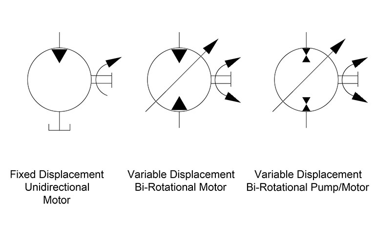
The base symbol for the hydraulic pump (Figure 1) is actually quite simple. It starts with the standard circle and a directional arrow pointing out one end from within that circle. The solid-filled triangle makes this a hydraulic pump while pneumatic pumps (and most pneumatic symbols) are outlines only. There exist no other options for this particular pump symbol, which can be accurately described as a fixed displacement, unidirectional hydraulic pump.
It’s rare to see a pump in any orientation but North when reading schematics, and they are often paired below to a line terminating into the reservoir symbol, which I show just once. If multiple components such as filters, ball valves, accessories or even other pumps are used, the tank line can be widened as needed. Other designers prefer to show every tank line terminate into the same small symbol, while others will place a tank symbol right at every component requiring it, just is done in electrics with the ground symbol.
Unfortunately, and except for rare circumstances, there are no symbology differences between the type of pumps available. The symbols for a gear pump, a vane pump, a piston pump or any other type of physical configuration does not carry with it any symbolic difference, nor does it matter as you’ll find out by the end of this.
The second pump is not much different from the first, with the exception of the second black directional triangle, which informs us this pump can expel fluid from what would otherwise be the suction port. This is the symbol for a bi-rotational pump, which is rare outside of advanced mobile machinery, especially in the fixed displacement version as shown. Although a series of check valves could allow both ports to become either the tank or pressure lines, depending upon the direction of rotation, this is still a rare concept.
The third symbol in Figure 1 illustrates the very simplified version of the variable displacement, pressure compensated, unidirectional hydraulic pump. It includes the variable arrow across the entire symbol, explaining that the pump displacement can be modified. To the left is a smaller arrow, and as you may have picked up on from earlier symbol articles, it tells us the pump displacement varies automatically with pressure compensation. As a fan of ISO 1219 symbology, I don’t find this symbol visually pleasing, concise as it is.
My favourite symbol to express the pressure compensated pump is the smaller of the two symbols in Figure 2. This is a slightly more detailed example of the symbol I depicted in Hydraulic Symbology 101, and I’ve added colour to help with the explanation. Don’t worry about the scary looking object to the right, we’ll get to that shortly.
For this particular symbol of the pressure compensated pump, the shaft sticks out to the right, which can be attached to the square of a combustion engine prime mover symbol or the circular symbol of an electric motor. The semicircular arrow shows us the shaft rotates clockwise, or to the right since rotation direction is always observed from the vantage point of the shaft end.
The variable arrow bisects the pump symbol and of course tells us the pump is adjustable displacement. The method of displacement control is defined by the compound symbol attached to the pump’s left. Under the long rectangle is a spring with a variability arrow, which represents the pressure compensator spring, itself semi-enclosed and attached to the bottom of the pump’s variable arrow. Opposite the spring is a triangular input for pilot pressure, and this juxtaposition is intentional.
The orange pilot signal is taken directly from the red system pressure line exiting the pump, with the dashed orange line confirming it is indeed pilot energy. The spring setting fights with pilot pressure to infinitely and smoothly adjust the flow rate to match downstream pressure drop equal to the compensator setting. For example, if the setting is 3,000 psi, any downstream combination of load and flow-related pressure below 3,000 psi will see the spring maintain full displacement of the swashplate, producing full pump flow.
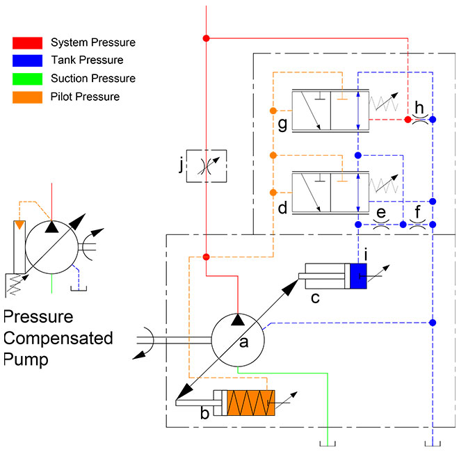
Moving along to the scary looking thing on the right, we have here the detailed breakdown of the variable displacement, pressure compensated, load-sensing, unidirectional hydraulic pump. You’ve likely seen this symbol before because the manufacturers prefer to show this level of detail, especially to differentiate advanced controls options like remoted compensation or horsepower control. This “load-sensing pump” will make sense to you shortly. I’ll warn that it will take some time and effort to understand this symbol as you methodically work through the rest of this article.
Starting with the pump (a), it has the diagonal variability arrow bisecting the circle and is attached to the rod ends of two cylinders. Cylinder (b) is the bias piston meant to force the pump to full displacement whenever possible, a task made easier by spring pushing the piston forward. Some pumps make do with only a strong spring, but this example is balanced with pilot energy. Affixed on the right is a tiny object with a variable arrow, which can be adjusted to move left or right within the cylinder. Not all pumps have this additional component, which is the minimum volume stop, preventing the bias piston from retracting fully, which subsequently prevents fully standby of the pump.
If you’re familiar with cylinder symbols, you’ll see that (c) also looks like a single acting cylinder with a stroke adjustor at the cap side. This is the control piston, which will always be a larger bore diameter than the bias piston. The control piston’s stroke adjustment is called the maximum volume stop and is used to modify the maximum displacement of the pump, convenient when you need a displacement between the two sizes available for the chosen pump. The two “cylinders” are attached by their rods to each other, and as one extends the other must retract and vice versa, and I’ll explain shortly why and how their battle develops.
Because all load sensing pumps must be pressure compensated, I’ll start with (d), which is the pressure compensator. Although it looks different, it is essentially a relief valve governing the control piston (c). It’s shown in its neutral condition, where it bleeds the chamber of the control piston (c) through orifice (e), orifice (f), and also through the other compensator (g) where it can choose any flow path directly to tank. Regardless of its flow path, pilot energy inside the control piston (c) is zero, so it loses the battle with the bias piston (b) and the pump is on full displacement pump at its highest rate.
The load sense compensator (g) looks much the same as the pressure compensator (d) and is similar in function except where it takes pilot energy and what it does with it afterward. As with the pressure compensator symbol (d), it is a 3-way, 2-position valve that is spring-offset with adjustable pressure settings for both. Each is supplemented with the parallel lines above and below both positional envelopes, and these lines tell us the valve is infinitely variable between the two positions.
The variable orifice at (j) could be any flow control, lever valve or proportional valve used to adjust flow (which creates backpressure when reduced) in the red system pressure line starting at the pump. You can see the node just after the pump outlet that combines system pressure with pilot lines supplying the bias piston and both compensators. Let’s first take the load sense compensator (g) out of the picture and describe the pressure compensator (d) and what occurs during operation.
When the pump fires up, and assuming all downstream directional valves are closed, the spring inside the bias piston (b) fully strokes the pump to max displacement. This immediately creates pressure in the work and pilot lines as fluid fills the plumbing with no exit strategy, and this rise in pressure at the pilot line at (d) forces the pressure compensator to shift to the right. The second pilot line attached to the top of compensator (d) allows pilot energy to enter through line (i) where it fills the control piston (c) rapidly. Because the control piston is larger bore than the bias piston, it wins the fight and moves the pump’s variable arrow to reduce displacement until the only flow is what is required to overcome leakage. The pump is on “standby.”
Now when a downstream directional valve is opened, a flow path is created that drops system pressure to below the setting of the (d) compensator, and it immediately succumbs to spring pressure and snaps back to near its neutral setting, opening the drain lines once again to tank. The orifices (e) and (f) dampen the motion of the compensator, preventing rapid oscillations, but the orifice also prevents pressure spikes into the pump’s case. They also ensure that pressure doesn’t decay from the control piston (c) when system pressure degrades rapidly for fractions of a second. Flow from the pump will be balanced by the opposing bias and control pistons to match downstream pressure drop at exactly the pressure compensator setting.
Finally, we look at the operation of the load sense compensator (g) shown on top. It also receives a pilot signal directly from the pump outlet, but you’ll see that it also gets a competing signal from the work line after the metering orifice. The pressure signal at (g) compares the combined effort of the spring value and the load-sense pilot signal just before (h). The setting of the pressure compensator (d) is much higher than the setting of the load sense compensator (g), which is set to create reasonable pressure drop across (j). If the (d) compensator is set to 3,000 psi, it’ll only see this pressure on standby or max load pressure, while the (g) compensator might be set to 300 psi, where it measures pressure drop across (j) valve.
Typically a load sense circuit will have multiple orifices in a load sense network all feeding back a pilot signal to the load sense compensator (g), where it picks the highest pressure signal and meters the pump’s flow to match that pressure differential and provides just enough flow to satisfy the desired flow rate at the desired work pressure plus the pressure of the load sense compensator’s spring value. For example, if load pressure is 1,000 psi, the pump will hold pressure at 1,300 psi, providing the extra 300 psi just to create flow across the metering valve (j).
This symbol shows you that no matter the initial feeling of complexity, breaking down any schematic thoughtfully reveals its purpose of design. I fell in love with hydraulics when I learned about the load sensing concept. That just using columns of fluid pressure to create an efficient supply and demand scenario to satisfy many downstream actuators with essentially the exact flow and pressure they need for the job, and little more, I found exhilarating.

The symbols for hydraulic motors, especially in their simpler forms, are very similar to those of hydraulic pumps. If you haven’t already had the chance, see my article on pumps symbols here first. The directional arrow that points inward to accept fluid power energy is the primary difference between pump and motor symbols, and in Figure 1 you can see the simple fixed displacement, unidirectional hydraulic motor.
The shaft symbol may or not be present in a schematic, as with the rotation direction arrow. The shaft symbol may even include a symbolic depiction of the device being rotated, such as a wheel or a drum. Always remember although there are ANSI and ISO standards for drawing schematics, the engineer or designer may draw a circuit as they wish, so you may come encounter modified or unknown symbols.
The second symbol stands for the variable displacement bi-rotational motor. The dark triangle depicting the direction of hydraulic energy is now diametrically opposed to indicate the motor takes fluid from both ports. If it’s not plain enough already, the shaft has bidirectional rotation arrows bent around the shaft as well. You will also notice both ports are now open to flow rather than one that terminates at the tank as the first symbol. Finally, the tell-tale variable arrow dissects the circle, showing us the motor has a variable displacement, although telling us nothing of how that might occur.
The final symbol of Figure 1 is just like the last, save for two slight differences. The dark flow triangles are stacked atop each other and in opposing directions. This configuration represents a unit capable of both pumping and absorbing hydraulic energy, or more succinctly, the variable displacement, bi-rotational pump-motor. Used in few locations other than a drive application, such as the clever hydraulic hybrid applications for dump trucks or loaders, where stopping energy can be fed back into the system and stored in an accumulator.
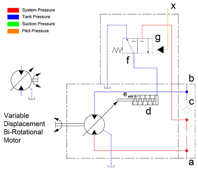
Motor controls, aside from hydrostatic drives, are not usually overly complicated. The variable displacement, bi-rotational hydraulic motor shown on the left in Figure 2 has everything the earlier one did save the case drain line. Being a simplified symbol, as most fluid power symbols are, it gives you basic details on what it does but doesn’t provide the scope of performance, the method of construction or dimensional envelope. The apparent mess of lines and shapes to the right does, in fact, break down the method of operation, at the very least.
By this point, the motor symbol needs no explanation, so we’ll skip that part. Denotations (a) and (b) are the work ports, which are the common characters used to denote work ports, even on the directional valves as well. Each work port terminates not only at the motor ports but also at the (c) component, which is called a shuttle valve. The shuttle valve is a 3-port check valve that always provides a flow path for the higher of the two work ports. In this case, work pressure is coming from port (a), so the check valve shuts off port (b) due to pressure differential.
The part looking like a spring-retracted cylinder can be considered as such, and this is the object primarily responsible for controlling motor displacement, which in turn will change torque and speed. The spring keeps the bias piston retracted, providing the motor with full displacement until told otherwise. How it gets told otherwise is through the pilot valve operated 3/2 valve shown at (g). In its neutral state, it provides a flow path to tank for the bias piston so that motor’s tendency is full flow.
When a pilot valve somewhere upstream of (x) is activated, fluid enters the pilot chamber of the 3/2 valve (g), where it shifts to provide pilot energy sourced from the shuttle valve (c) to the bias piston. The bias piston now shifts fully, reducing the swashplate angle to reduce flow. Just how low the displacement goes is dictated by the tiny stroke limiter (e), which is just an adjustment screw that prevents the swashplate from reducing its angle further. The orifice at (f) is used to dampen the actions of the pilot energy working to move the bias piston. Without this orifice, the pump may shift too quickly or be susceptible to work pressure fluctuations coming from ports (a) or (b).
A motor such as this might be used as a two-speed transmission. The full flow, large angle of the swashplate provides higher torque yet slower speed while shifting the pilot valve energizes the bias piston, reducing swashplate angle to reduce displacement, therefore increasing speed while lowering torque. The shuttle valve ensures pilot energy is available regardless of motor rotation direction, however, it should be noted that the pilot valve could instead be a mechanical lever or some sort of torque limiting valve.
The standard hydraulic cylinder depicted way back in Hydraulic Symbology 102 is as clean and pure as one can ask, but you’d be surprised at the number of ways a cylinder can be drawn (and therefore constructed). Where possible in these examples, I’ve made a wide piston rather than the single line in previous examples, and also shown the rod as a long rectangle as well. For some of these examples, it is required to make sense of the symbol, so I used it across the board for the purpose of consistency.
The Double Rod Cylinder is quite easy to understand. Instead of a single head, cap and rod, this component now has two rods joined by a common piston and is then guided through two heads. This symbol looks very much like its construction, at least from the point of view of the piston rod assembly.
The Spring Retract Cylinder is another that takes little to decode. It starts by looking much like a regular cylinder symbol, but now with a giant spring placed in the annular (rod side) area of the cylinder. Imagine now that pressure is applied to the cap side and the piston starts to extend. As it does, the spring compresses in an attempt to once again retract the cylinder without the help of rod side hydraulic energy. When pressure is relieved from the cap side, the cylinder retracts using the compressed energy stored within the spring.
A ram is a hydraulic cylinder with one fluid port on a tube that is stuffed with a rod. The rod is typically a large diameter relative to the body because the base of the rod also performs as the piston. So if your ram has a 4-in. rod, then your ram has a 4-in. piston. The port can be drawn nearly anywhere on a ram because fluid coming in the side will still extend the cylinder, as fluid pressurizing the rod radially has no effect on it.
When a load of a dump truck or other piece of machinery employing a telescopic cylinder goes over center (meaning past its pivot point), the load then pulls the rod out further. Gravity is no longer able to retract the cylinder and lower the dump body, so a Double Acting Telescopic cylinder is required. It’s very much like the single-acting example, but now with actual pistons and a complicated porting network. The symbol shows a piston rod within a piston rod within a piston rod, which fairly well represents how it is constructed.
Motors and actuators in real applications rarely employ some of the options shown, but they’re important to know so you not only understand schematics that may come across your desk. As well, know what components are available by way of their symbol allows for creativity and diversity in your schematic creations.

The top symbol shows a fixed displacement hydraulic pump that rotates in an anticlockwise direction (shown by the arrow) when viewed onto the drive flange and drive-shaft. The black triangle shows it is a hydraulic pump and which direction the flow will go in.
The middle symbol has an arrow through it indicating a variable displacement pump. It also shows a case drain line coming from the side of the pump casing. Generally, it is only fixed displacement pumps that can work without a case drain line.
The vector stencils library "Hydraulic pumps and motors" contains 74 symbols of hydraulic pump vector stencils, hydraulic motor symbols for engineering drawings of fluid power and hydraulic control systems.
Hydrostatic pumps are positive displacement pumps while hydrodynamic pumps can be fixed displacement pumps, in which the displacement (flow through the pump per rotation of the pump) cannot be adjusted, or variable displacement pumps, which have a more complicated construction that allows the displacement to be adjusted." [Hydraulic pump. Wikipedia]
"A hydraulic motor is a mechanical actuator that converts hydraulic pressure and flow into torque and angular displacement (rotation). The hydraulic motor is the rotary counterpart of the hydraulic cylinder.
Conceptually, a hydraulic motor should be interchangeable with a hydraulic pump because it performs the opposite function - much as the conceptual DC electric motor is interchangeable with a DC electrical generator. However, most hydraulic pumps cannot be used as hydraulic motors because they cannot be backdriven. Also, a hydraulic motor is usually designed for the working pressure at both sides of the motor.
Hydraulic pumps, motors, and cylinders can be combined into hydraulic drive systems. One or more hydraulic pumps, coupled to one or more hydraulic motors, constitutes a hydraulic transmission." [Hydraulic motor. Wikipedia]
The shapes example "Design elements - Hydraulic pumps and motors" was created using the ConceptDraw PRO diagramming and vector drawing software extended with the Mechanical Engineering solution from the Engineering area of ConceptDraw Solution Park.
There are 5 types of hydraulic motor found in hydraulic system.Find here all hydraulic symbol for motor. One directional rotary fixed displacement. Two directional rotary fixed displacement. One directional variable displacement. Two directional rotary displacement.Read more…
Symbols of hydraulic circuit includes Transmission line symbols Hydraulic pump Hydraulic motor Cylinder Air line service Direction control valves Flow control valves Pressure control valves Pressure switch Pressure gauge Temperature gauge flow meter Electric motorRead more…
Hydraulic circuit diagram is the graphics representation of the hydraulic component interconnected.Basics of hydraulic circuits.Hydraulic system design.Hydraulic circuit explanation. Hydraulic circuit explanation Main parts of hydraulics are needed to designs are Hydraulic power pack consists.-Read more…
What is intensifier in hydraulics? Hydraulic intensifier diagram and working principle. Intensifier multiply hydraulic pressure.It can develop higher pressure than the pump developed. Example:- Piercing machine riveters Working principle of intensifier In intensifier we applyRead more…
What is hydraulic accumulator?What is working principle of hydraulic accumulator?Use of hydraulic accumulator. Function It is to store energy and provide back up during system failure . It can be called as capacitance of theRead more…
Working principle of hydraulic pumps-It convert mechanical energy by pushing the hydraulic fluid into the system. It some times called as generator.It is designed to give motion or flow of fluid. Pump push the hydraulicRead more…
Different types of pump in hydraulic systems are gear pump,Vane pump,etc. Types of pump in hydraulic Positive displacement pump Rotary pump Reciprocating pumps Non positive displacement pump Centrifugal pumps Axial flow pumps Radial flow pumpsRead more…
How to work hydraulic system. Steps Description Handling of hydraulic unit Hydraulic unit should be cleaned before delivery from manufacturing place.Check oil tank ,there should not any foreign particleand dirty oil.Use clean oil.The life ofRead more…
Hydraulic system maintenance schedule is required to prepare and follow to avoid breakdown. Check List Daily Weekly Monthly Quaterly Half yearly Yearly Oil Property,detorioration X X Tank Cleaning X Water Cleaningfrom Oil X Oil LevelRead more…
IPH-4B-25-LT-11 -Specification of hydraulic pump (Example). Specification Description IPH IPH Series IP pump 4 Size(Example-2,3,4,5,6) B Mounting(Example-A :Foot Mounting,B:Flange Mounting) 25 Delivery(cc/rev) LT Auxiliary symbol(No Symbol:Clock wise rotation,T(LT):With threaded type flange kit,E(EL):With welded type flangeRead more…
What is the principle of Hydraulic system? Hydraulic System works on Pascal’s law. Pascal’s Law Pressure of fluid in an enclosed is uniform in all the direction. Functions of hydraulic system The main function ofRead more…
Schematic diagram or block diagram of hydraulic system. Block diagram of hydraulic system consists of Tank which is connected to pump set which deliver oil pressure. After pump pressure relieve and pressure reduce valve isRead more…
What are limit switches and symbols of limit switches?How do limit switches work? What are limit switches Normally Open Unoperated Condition Operated condition Normally Closed Unoperated Condition Operated Condition
Types of Hydraulic pressure switch. There are four main types of hydraulic pressure switches. Gage Pressure switch Absolute Pressure switch vacuum pressure switch Differential pressure switch Mechanical Pressure switches Electronics Pressure switches Mechanical Pressure SwitchRead more…

Hydraulics engineers regularly encounter these diagrams, but these symbols can be daunting to interpret if you have limited experience with schematics and the fluid power industry.
On this page, Carr Lane ROEMHELD provides a comprehensive table outlining the definitions of each symbol used in a hydraulic diagram. Engineers can use this page as a reference to determine common schematic symbols used in fluid power, hydraulics, pneumatics, diagrams and circuits.

I. Fixed Displacement Pump – These pump has a set flow rate means every stroke of the motor moves same amount of fluid. Fixed displacement pumps are perfect for single jobs that to be repeated indefinitely over long periods of time. There are three types of fixed displacement pump : Gear Pump, Gerotor Pump, Screw Pump.
II. Variable Displacement Pump – In Variable displacement pumps flow rate and outlet pressure can be changed as the pump operates. They are used to power a wider variety of tool, but require more expense and more attention. There are four types of variable displacement pump: Bent Axis Pump, Axial Piston Pump, Radial Piston Pump, Rotary Vane Pump.
A hydraulic motor is a mechanical hydraulic actuator that converts hydraulic energy or hydraulic pressure into torque and angular displacement / rotation.
Hydraulic cylinder is a mechanical hydraulic actuator that converts hydraulic energy or hydraulic pressure into linear displacement. It consists of cylindrical barrel, piston and piston rod.
I. Pressure Relief Valve – They are designed to protect hydraulic system when pressure in the system increases beyond the specified design pressure or maximum working pressure. They are normally closed and it opens when the pressure exceeds a specified maximum value and diverts the pump flow back to reservoir or tank internally. They are located near hydraulic pump.
II. Pressure Reducing Valve – They are design to limit and maintain outlet pressure. They are normally open and closed if the pressure exceed beyond specified design pressure at outlet. They are located near hydraulic actuator.
IV. Counterbalance Valve – Counterbalance valves are used in hydraulic systems working with running-away or suspended load. They are designed to create backpressure at the return line of the actuator to prevent losing control over the load.
They control the returning flow in relation to the flow being directed into opposite side of the actuator. It is used in hydraulic system to influence the speed of hydraulic motor and hydraulic cylinder independent to the load (prevent running away).
It is a electro mechanically operated valve. The valve is control by electric current through a solenoid. The function of solenoid valve in hydraulic system is to shut off, distribute and release fluid.

For novices in the fluid power industry, lack of understanding between the fixed flow and variable flow pumping concepts is quite common. A hydraulic pump has one mission, and that is to transform incoming mechanical energy at its shaft into hydraulic energy capable of transferring force to actuators somewhere downstream. This transfer of force is common to both fixed and variable pumps, but the method delivery is quite different.
The displacement of a pump is defined by the theoretical volume the gears, vanes or pistons will displace in one revolution. If a pump is 30 cc, it will theoretically push 30 ml of fluid in a single rotation, or about 1.8 in.3. With a fixed displacement pump, these 30 cm3 do not change, regardless of how the pump is controlled or what occurs downstream. In reality, actual flow varies based on efficiency, speed and pressure, but that’s a different story. If you need less flow than the pump is rated for, the excess flow must be diverted or relieved to tank.
A variable displacement pump has a method of increasing or reducing displacement either manually, hydraulically or electronically. The method of displacement change depends upon the pump’s structure, differing between piston and vane pumps, and between those two, iterations still.
An axial piston pump’s maximum displacement is determined by the quantity and bore area of the pistons multiplied by the stroke length. Although the stroke length can be fixed, such as with most radial and bent-axis piston motors, the stroke can also be varied. Variable displacement axial piston pumps use a swashplate to guide the pistons as they reciprocate while rotating about the shaft’s axis. The angle the swashplate sits at relative to the pistons dictates how long or short the piston stroke is, and with variable pumps, the swashplate is supported by bearings or bushings.
On opposing sides of the swashplate sits a bias piston (and spring) and a control piston. A variable displacement piston pump is designed to be “on stroke,” meaning it wants to pump with full displacement whenever possible. The control piston is operated by what is essentially a relief valve, and if downstream pressure rises above this pressure compensator setting, it will push the control piston out to reduce the angle of the swashplate. With the swashplate angle reduced, the pistons now travel a fraction of their stroke potential. Because displacement is dictated by the area, quantity and stroke of the pistons, pump volume is now reduced. If downstream pressure is still higher than the compensator setting, the stroke will be reduced until the swashplate angle is nearly zero, where it only pumps enough to maintain lubrication.
Swashplate angle can be changed mechanically, with a lever or wheel, but in advanced applications, electro-proportional valves operate the control piston to adjust pump flow as required. This is an advanced concept used in closed loop electronic control applications. A proportional pressure valve will adjust the control piston of the pump with guidance from the PLC, providing exact flow required by the machine under varying conditions.

Designed for power and speed, the Oilgear PVV open-loop axial-piston hydraulic pumps can handle large, heavy-duty systems. Manufactured with advanced engineering and computer-optimized, the PVV pump range delivers up to 450 Bar / 560 horespower which equates to four times the horsepower at less than half the cost of other manufacturers pumps.
With it"s compact design available in several displacements, the PVV pumps offer a large selection of readily interchangeable controls. With improved response controls and reduced noise levels, its rugged cylinder design enhances performance.
The patented, pressure lubricated swashblock design offers high performance for high-cycling operations. It also contributes to the pump’s ability to run on low-viscosity fluids, including high water content, fire-resistant and other special fluids.
Zeus Hydratech fully supports the Oilgear PVV pump product line and is the only valid source for OEM parts. All Oilgear repairs are machined and tested per our original factory specifications.
The Oilgear PVWC is a rugged and tough closed loop pump and offers low horsepower for high-performance applications. Like many of the pumps within the Oilgear range, the PVWC variable displacement pumps are avaiable with multiple mechanical, hydraulic and electrohydraulic servo valve control options which facilitate easy field interchangeability. With three capacities per single frame size, the PVWC pumps allow users to select their required level of capacity and pressure, while providing maximum control range and sensitivity.
As with all Oilgear pumps, all contact surfaces such as the cylinder surface running on the valve plate and the pistons running on the swashblock surface are all hardened for incredible durability. With excellent contamination-resistance properties, PVWC pumps are capable of operating with low viscosity fluids, including high water content, fire resistant and other specialist fluids.
Quiet in operation, super high efficiency, compact design, competitive pricing and impressive lead time are the key attributes of the Oilgear PVWC closed loop piston pump. Available in several displacements, the PVWC pumps offer a large selection of readily interchangeable controls. With improved response controls and reduced noise levels, its rugged cylinder design enhances performance.
The patented, pressure lubricated swashblock design offers high performance for high-cycling operations. It also contributes to the pump’s ability to run on low-viscosity fluids, including high water content, fire-resistant and other special fluids.
Zeus Hydratech fully supports the Oilgear PVWC pump product line and is the only valid source for OEM parts in the South of the UK. All Oilgear repairs are machined and tested per our original factory specifications.

A pressure compensator is a device built into some pumps for the purpose of automatically reducing (or stopping) pump flow if system pressure sensed on the pump outlet port, should rise above a pre-set desired maximum pressure (sometimes called the "firing" pressure). The compensator prevents the pump from being overloaded if an overload is placed on the hydraulic system.
A compensator is built into the pump at the factory and usually cannot be added in the field. Any pump built with variable displacement can be controlled with a compensator. These include several types of axial piston pumps and unbalanced (single lobe) vane pumps. Radial piston pumps can sometimes be built with variable displacement but do not lend themselves readily to this action. Most other positive displacement pumps including internal and external gear, balanced (double lobe) vane, gerotor, and screw types cannot be built with variable displacement.
Figure 1 is a schematic of a check valve axial piston pump, variable displacement, controlled with a pressure compensator. The pistons, usually 5, 7, or 9 in number, are stroking inside a piston block which is keyed to and is rotating with the shaft. The left ends of the pistons are attached through swivel joints, to piston shoes which bear against and slide around on the swash plate as the piston block rotates. The swash plate itself does not rotate; it is mounted on a pair of trunnions so it can swivel from neutral (vertical) position to a maximum tilt angle. The angle which the swash plate makes to the vertical causes the pistons to stroke, the length of stroke being proportional to the angle. Normally, at low system pressures, the swash plate remains at its maximum angle, held there by spring force, hydraulic pressure, or by the dynamics of pump construction, and pump flow remains at maximum. The compensator acts by hydraulic pressure obtained internally from the pump outlet port. When pump pressure rises high enough to over-come the adjustable spring behind the compensator piston, the "firing" pressure has been reached, and the compensator piston starts to pull the swash plate back toward neutral, reducing pump displacement and output flow. The spring in the compensator can be adjusted for the desired maximum or "firing" pressure.
Under working conditions, on a moderate system overload, the compensator piston reduces the swash plate angle just enough to prevent the system pressure from exceeding the "firing" pressure adjusted on the compensator. On severe overloads the compensator may swing the swash plate back to neutral (vertical) to reduce pump flow to zero.
Maximum Displacement Stops. Some pumps are available with internal stops to limit the tilt angle of the swash plate. These stops limit the maximum flow and limit the HP consumption of the pump. They may be fixed stops, factory installed and inaccessible from the outside, or they may be externally adjustable with a wrench.
Manual Control Lever. Some pressure compensated pumps, especially hydrostatic transmission pumps, are provided with an external control lever to enable the operator to vary the swash plate angle (and flow) from zero to maximum. On these pumps the pressure compensator is arranged to override the manual lever and to automatically reduce the swash plate angle if a system overload should occur even though the operator control lever is still shifted to maximum displacement position.
Basically the pressure compensator is designed to unload the pump when system pressure reaches the maximum design pressure. When the pump is unloaded in this way, there is little HP consumed and little heat generated even though pressure remains at the maximum level, because there is no flow from the pump.
Variable displacement pumps are usually more expensive than fixed displacement types, but are especially useful in systems where several branch circuits are to be supplied from one pump, and where full pressure may be required simultaneously in more than one branch, and where the pump must be unloaded when none of the branches is ill operation. If individual 4-way valves are used in each branch, each valve must have a closed center spool. The inlet ports on all 4-way valves must be connected in parallel across the pump line. However, if all branch circuits are operated from a bank valve of the parallel type, a pressure compensated variable displacement pump may not be necessary; a fixed displacement pump, gear, vane, or piston, may serve equally well because the bank valve will unload the pump when all valve handles are placed in neutral, but when two or more handles are simultaneously shifted, their branch circuits will automatically be placed in a parallel connection.
As in all hydraulic systems, more pump oil will flow to the branch with the lightest load. Bank valve handles can be modulated to equalize the flow to each branch. When individual 4-way valves are used in each branch, flow control valves may be installed in the branch circuits and adjusted to give the flow desired in each branch.
Figure 2 shows a multiple branch circuit in which a variable displacement pump is used to advantage. Individual 4-way valves, solenoid operated, are used for each branch, and they have closed center porting. Please refer to Design Data Sheet 54 for possible drift problems on a pressure manifold system. A pressure relief valve is usually required even with a pressure compensated pump due to the time interval required for the swash plate to reduce its tilt angle when a sudden overload occurs. The relief valve will help absorb part of the pressure spike generated during this brief interval. It should be adjusted to crack at about 500 PSI higher than the pressure adjustment of the compensator piston spring to prevent oil discharge across it during normal operation.
All hydrostatic transmission systems use a variable displacement pump with pressure compensator, and often combine the compensator with other controls such as the horsepower input limiter, load sensing, flow sensing, or constant flow control.

When you need peak performance from a variable-displacement axial-piston pump, the Oilgear pump PVV line is ready. No matter what pressure and flow demands you face, these pumps rise to the challenge.
Designed for power and speed, PVV open-loop axial-piston hydraulic pumps by Oilgear can handle large, heavy-duty systems. Made with advanced engineering and computer-optimized, the PVV line delivers up to 560 horsepower. That’s four times the horsepower at less than half the cost of other models.
A compact design available in several displacements, PVV pumps offer a large selection of readily interchangeable controls. With improved response controls and reduced noise levels, its rugged cylinder design enhances performance.
The patented pressure lubricated swashblock design offers high performance for high-cycling operations. It also contributes to the pump’s ability to run on low-viscosity — including high water content, fire-resistant and other special fluids. That fluid compatibility continues to set Oilgear apart.
Oilgear fully supports the PVV pump product line and is the only valid source for OEM parts. All Oilgear repairs are machined and tested per our original factory specifications.
Oilgear makes some of the longest-lasting, most reliable pumps in the world. Learn more about the proprietary design of the Oilgear variable-displacement, axial-piston pump line.


 8613371530291