
variable displacement hydraulic pump symbol in stock
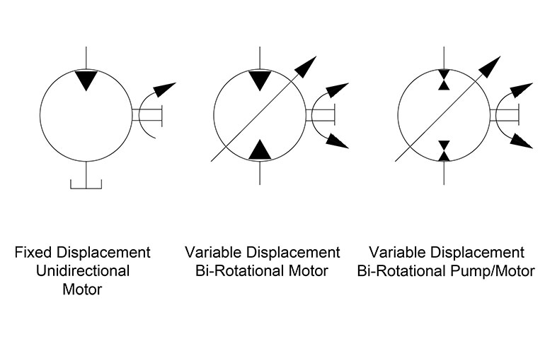
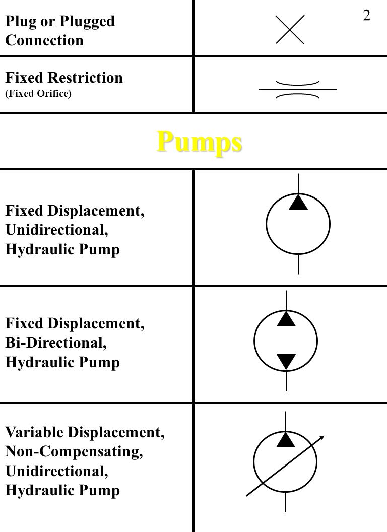
The base symbol for the hydraulic pump (Figure 1) is actually quite simple. It starts with the standard circle and a directional arrow pointing out one end from within that circle. The solid-filled triangle makes this a hydraulic pump while pneumatic pumps (and most pneumatic symbols) are outlines only. There exist no other options for this particular pump symbol, which can be accurately described as a fixed displacement, unidirectional hydraulic pump.
It’s rare to see a pump in any orientation but North when reading schematics, and they are often paired below to a line terminating into the reservoir symbol, which I show just once. If multiple components such as filters, ball valves, accessories or even other pumps are used, the tank line can be widened as needed. Other designers prefer to show every tank line terminate into the same small symbol, while others will place a tank symbol right at every component requiring it, just is done in electrics with the ground symbol.
Unfortunately, and except for rare circumstances, there are no symbology differences between the type of pumps available. The symbols for a gear pump, a vane pump, a piston pump or any other type of physical configuration does not carry with it any symbolic difference, nor does it matter as you’ll find out by the end of this.
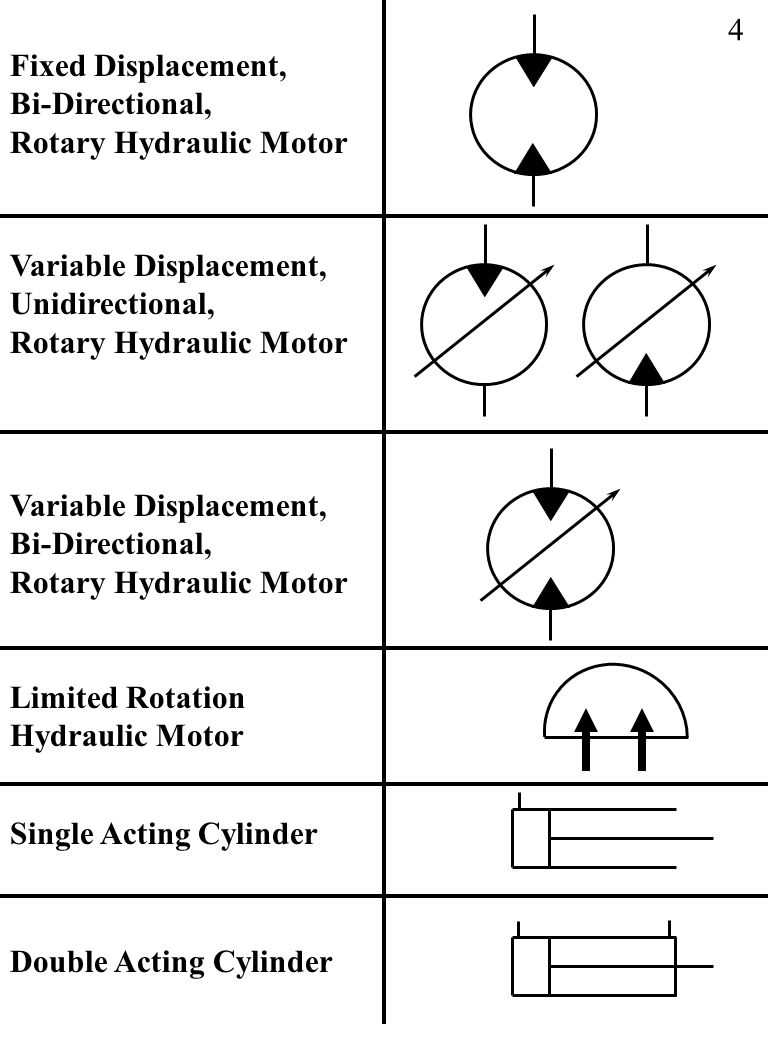
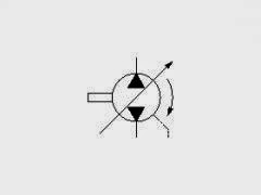
The second pump is not much different from the first, with the exception of the second black directional triangle, which informs us this pump can expel fluid from what would otherwise be the suction port. This is the symbol for a bi-rotational pump, which is rare outside of advanced mobile machinery, especially in the fixed displacement version as shown. Although a series of check valves could allow both ports to become either the tank or pressure lines, depending upon the direction of rotation, this is still a rare concept.
The third symbol in Figure 1 illustrates the very simplified version of the variable displacement, pressure compensated, unidirectional hydraulic pump. It includes the variable arrow across the entire symbol, explaining that the pump displacement can be modified. To the left is a smaller arrow, and as you may have picked up on from earlier symbol articles, it tells us the pump displacement varies automatically with pressure compensation. As a fan of ISO 1219 symbology, I don’t find this symbol visually pleasing, concise as it is.
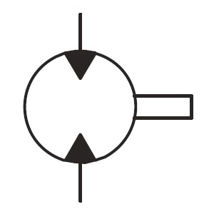
My favourite symbol to express the pressure compensated pump is the smaller of the two symbols in Figure 2. This is a slightly more detailed example of the symbol I depicted in Hydraulic Symbology 101, and I’ve added colour to help with the explanation. Don’t worry about the scary looking object to the right, we’ll get to that shortly.
For this particular symbol of the pressure compensated pump, the shaft sticks out to the right, which can be attached to the square of a combustion engine prime mover symbol or the circular symbol of an electric motor. The semicircular arrow shows us the shaft rotates clockwise, or to the right since rotation direction is always observed from the vantage point of the shaft end.
The variable arrow bisects the pump symbol and of course tells us the pump is adjustable displacement. The method of displacement control is defined by the compound symbol attached to the pump’s left. Under the long rectangle is a spring with a variability arrow, which represents the pressure compensator spring, itself semi-enclosed and attached to the bottom of the pump’s variable arrow. Opposite the spring is a triangular input for pilot pressure, and this juxtaposition is intentional.
The orange pilot signal is taken directly from the red system pressure line exiting the pump, with the dashed orange line confirming it is indeed pilot energy. The spring setting fights with pilot pressure to infinitely and smoothly adjust the flow rate to match downstream pressure drop equal to the compensator setting. For example, if the setting is 3,000 psi, any downstream combination of load and flow-related pressure below 3,000 psi will see the spring maintain full displacement of the swashplate, producing full pump flow.
Moving along to the scary looking thing on the right, we have here the detailed breakdown of the variable displacement, pressure compensated, load-sensing, unidirectional hydraulic pump. You’ve likely seen this symbol before because the manufacturers prefer to show this level of detail, especially to differentiate advanced controls options like remoted compensation or horsepower control. This “load-sensing pump” will make sense to you shortly. I’ll warn that it will take some time and effort to understand this symbol as you methodically work through the rest of this article.
Starting with the pump (a), it has the diagonal variability arrow bisecting the circle and is attached to the rod ends of two cylinders. Cylinder (b) is the bias piston meant to force the pump to full displacement whenever possible, a task made easier by spring pushing the piston forward. Some pumps make do with only a strong spring, but this example is balanced with pilot energy. Affixed on the right is a tiny object with a variable arrow, which can be adjusted to move left or right within the cylinder. Not all pumps have this additional component, which is the minimum volume stop, preventing the bias piston from retracting fully, which subsequently prevents fully standby of the pump.
If you’re familiar with cylinder symbols, you’ll see that (c) also looks like a single acting cylinder with a stroke adjustor at the cap side. This is the control piston, which will always be a larger bore diameter than the bias piston. The control piston’s stroke adjustment is called the maximum volume stop and is used to modify the maximum displacement of the pump, convenient when you need a displacement between the two sizes available for the chosen pump. The two “cylinders” are attached by their rods to each other, and as one extends the other must retract and vice versa, and I’ll explain shortly why and how their battle develops.
Because all load sensing pumps must be pressure compensated, I’ll start with (d), which is the pressure compensator. Although it looks different, it is essentially a relief valve governing the control piston (c). It’s shown in its neutral condition, where it bleeds the chamber of the control piston (c) through orifice (e), orifice (f), and also through the other compensator (g) where it can choose any flow path directly to tank. Regardless of its flow path, pilot energy inside the control piston (c) is zero, so it loses the battle with the bias piston (b) and the pump is on full displacement pump at its highest rate.
The load sense compensator (g) looks much the same as the pressure compensator (d) and is similar in function except where it takes pilot energy and what it does with it afterward. As with the pressure compensator symbol (d), it is a 3-way, 2-position valve that is spring-offset with adjustable pressure settings for both. Each is supplemented with the parallel lines above and below both positional envelopes, and these lines tell us the valve is infinitely variable between the two positions.
The variable orifice at (j) could be any flow control, lever valve or proportional valve used to adjust flow (which creates backpressure when reduced) in the red system pressure line starting at the pump. You can see the node just after the pump outlet that combines system pressure with pilot lines supplying the bias piston and both compensators. Let’s first take the load sense compensator (g) out of the picture and describe the pressure compensator (d) and what occurs during operation.
When the pump fires up, and assuming all downstream directional valves are closed, the spring inside the bias piston (b) fully strokes the pump to max displacement. This immediately creates pressure in the work and pilot lines as fluid fills the plumbing with no exit strategy, and this rise in pressure at the pilot line at (d) forces the pressure compensator to shift to the right. The second pilot line attached to the top of compensator (d) allows pilot energy to enter through line (i) where it fills the control piston (c) rapidly. Because the control piston is larger bore than the bias piston, it wins the fight and moves the pump’s variable arrow to reduce displacement until the only flow is what is required to overcome leakage. The pump is on “standby.”
Now when a downstream directional valve is opened, a flow path is created that drops system pressure to below the setting of the (d) compensator, and it immediately succumbs to spring pressure and snaps back to near its neutral setting, opening the drain lines once again to tank. The orifices (e) and (f) dampen the motion of the compensator, preventing rapid oscillations, but the orifice also prevents pressure spikes into the pump’s case. They also ensure that pressure doesn’t decay from the control piston (c) when system pressure degrades rapidly for fractions of a second. Flow from the pump will be balanced by the opposing bias and control pistons to match downstream pressure drop at exactly the pressure compensator setting.
Finally, we look at the operation of the load sense compensator (g) shown on top. It also receives a pilot signal directly from the pump outlet, but you’ll see that it also gets a competing signal from the work line after the metering orifice. The pressure signal at (g) compares the combined effort of the spring value and the load-sense pilot signal just before (h). The setting of the pressure compensator (d) is much higher than the setting of the load sense compensator (g), which is set to create reasonable pressure drop across (j). If the (d) compensator is set to 3,000 psi, it’ll only see this pressure on standby or max load pressure, while the (g) compensator might be set to 300 psi, where it measures pressure drop across (j) valve.
Typically a load sense circuit will have multiple orifices in a load sense network all feeding back a pilot signal to the load sense compensator (g), where it picks the highest pressure signal and meters the pump’s flow to match that pressure differential and provides just enough flow to satisfy the desired flow rate at the desired work pressure plus the pressure of the load sense compensator’s spring value. For example, if load pressure is 1,000 psi, the pump will hold pressure at 1,300 psi, providing the extra 300 psi just to create flow across the metering valve (j).
This symbol shows you that no matter the initial feeling of complexity, breaking down any schematic thoughtfully reveals its purpose of design. I fell in love with hydraulics when I learned about the load sensing concept. That just using columns of fluid pressure to create an efficient supply and demand scenario to satisfy many downstream actuators with essentially the exact flow and pressure they need for the job, and little more, I found exhilarating.

The top symbol shows a fixed displacement hydraulic pump that rotates in an anticlockwise direction (shown by the arrow) when viewed onto the drive flange and drive-shaft. The black triangle shows it is a hydraulic pump and which direction the flow will go in.
The middle symbol has an arrow through it indicating a variable displacement pump. It also shows a case drain line coming from the side of the pump casing. Generally, it is only fixed displacement pumps that can work without a case drain line.

For novices in the fluid power industry, lack of understanding between the fixed flow and variable flow pumping concepts is quite common. A hydraulic pump has one mission, and that is to transform incoming mechanical energy at its shaft into hydraulic energy capable of transferring force to actuators somewhere downstream. This transfer of force is common to both fixed and variable pumps, but the method delivery is quite different.
The displacement of a pump is defined by the theoretical volume the gears, vanes or pistons will displace in one revolution. If a pump is 30 cc, it will theoretically push 30 ml of fluid in a single rotation, or about 1.8 in.3. With a fixed displacement pump, these 30 cm3 do not change, regardless of how the pump is controlled or what occurs downstream. In reality, actual flow varies based on efficiency, speed and pressure, but that’s a different story. If you need less flow than the pump is rated for, the excess flow must be diverted or relieved to tank.
A variable displacement pump has a method of increasing or reducing displacement either manually, hydraulically or electronically. The method of displacement change depends upon the pump’s structure, differing between piston and vane pumps, and between those two, iterations still.
An axial piston pump’s maximum displacement is determined by the quantity and bore area of the pistons multiplied by the stroke length. Although the stroke length can be fixed, such as with most radial and bent-axis piston motors, the stroke can also be varied. Variable displacement axial piston pumps use a swashplate to guide the pistons as they reciprocate while rotating about the shaft’s axis. The angle the swashplate sits at relative to the pistons dictates how long or short the piston stroke is, and with variable pumps, the swashplate is supported by bearings or bushings.
On opposing sides of the swashplate sits a bias piston (and spring) and a control piston. A variable displacement piston pump is designed to be “on stroke,” meaning it wants to pump with full displacement whenever possible. The control piston is operated by what is essentially a relief valve, and if downstream pressure rises above this pressure compensator setting, it will push the control piston out to reduce the angle of the swashplate. With the swashplate angle reduced, the pistons now travel a fraction of their stroke potential. Because displacement is dictated by the area, quantity and stroke of the pistons, pump volume is now reduced. If downstream pressure is still higher than the compensator setting, the stroke will be reduced until the swashplate angle is nearly zero, where it only pumps enough to maintain lubrication.
Swashplate angle can be changed mechanically, with a lever or wheel, but in advanced applications, electro-proportional valves operate the control piston to adjust pump flow as required. This is an advanced concept used in closed loop electronic control applications. A proportional pressure valve will adjust the control piston of the pump with guidance from the PLC, providing exact flow required by the machine under varying conditions.

Variable Displacement Hydraulic Piston Pump used to convert mechanical energy to hydraulic fluid energy for control of hydraulic cylinders and other hydraulic mechanical systems within telescopically extendable booms, telehandlers. Model use: JLG® SkyTrak 8042, 10042, 10054.
Continental Hydraulics are at the forefront of engineering hydraulic solutions for over 50 years-a testament to a long-standing reputation built upon your challenges and opportunities. A worldwide leader- a one-stop-shop for valves, pumps, power units and proportional products-all assembled in the USA.
Continental Hydraulics PowrFlow™ PVR Vane Pumps deliver the rugged, reliable performance and value you’ve come to expect in all our products. They outperform sensitive piston pumps in harsh environments. PVR Vane Pumps deliver faster response, and require less external compensation compared to fixed displacement designs.

Boasting high pressure, low noise and energy saving technology in a compact package,the Nachi PZH is a variable-displacement axial-piston pump, designed to take on all demanding applications.
The PZH manages to save energy and reduce operating noise by utilising low friction engineering on all sliding surfaces. Pressure pulsation is also reduced, therefore providing a smoother pressure flow within the hydraulic circuit (which is incredibly important in any extrusion/forming process to reduce ripple in the finished manufactured part.)
For customers looking to specify a high performance a reliable 45cc/rev pressure compensated, axial piston pump capable of 350 bar, the PZH-2B makes a first-class substitute to the following pump models in the same pressure and flow class:
Zeus Hydratech fully supports the Nachi PZHpump product line and is the only valid source for OEM parts in the South of the UK. All Nachi repairs are machined and tested per our original factory specifications.
Variable-displacement piston pumps offer an array of controls based on pressure, flow, HP, or a combination of all of these. I’ll run through the basic types and reasons that you would use each.
One concept, which needs to be explained first, is the variable displacement. The amount of flow that each pump can provide is dependent on a rotating group of pistons. By varying the stroke of the pistons, we adjust the displacement of the pump. In a variable-displacement pump, we vary the angle of the rotating group, which is done by tilting the swash plate.
Pressure-compensated control is the most basic control for a variable-stroke piston pump. The swash plate of the pump is off-set by a heavy spring and an internal piston, holding the pump at maximum displacement. When the prime mover (an electric motor or another device) turns the pump shaft, the pump will produce maximum flow. The system pressure pushes back against the the internal piston, which is being held by the heavy spring. When the force of the system pressure is high enough to move the piston and overcome the spring pressure, the swash plate angle is lowered and the pump flow is reduced. As the load varies, the system pressure changes, which alters the angle of the swash plate. The pump will produce just enough flow to maintain the set pressure.
This is a very simple control method, and in certain applications, this is all you need. You can adjust the spring tension, but that’s it. Remember, the flow of the pump is not adjusted until you have built pressure at full displacement. You must have enough HP to take the pump to full pressure at full flow. If there is not enough HP, the prime mover will slow down or stall before the pressure begins to compensate and lower the flow.
An application example is using a hydraulic motor to operate a conveyor. The load is constant, and the motor requires about 1500 psi to handle the load. You set the piston pump compensator at 1600 psi and let it run. Your system will also need a safety relief in case of emergency. System pressure is adjusted using the pump compensator, and the system relief should be set a few hundred PSI higher than the pump compensator. If they are set too close, they can fight each other, causing the pump to go on and off stroke and/or the relief to open and close, causing inefficiency, heat, and vibration.
Let’s look at my initial application, but this time, it has a varying load. The conveyor requires 1500 psi to move 50% of the time, but the balance of the time, the system requires between 2250-2500 psi to move the load. With a standard pressure compensator, you would have to set the pump at 2600 psi to accomplish the work. When the work only requires 1500 psi, the pump will be trying to produce 2600 psi. Fifty percent of the time, your system will be operating at 1100 psi of inefficiency, which means heat.With a load-sense compensator, when the load requires 1500 psi, the pump will actually produce about 1700-1800 psi. Yes, this is 300-psi inefficient, but that is much better than 1100-psi inefficient.
With a varying load, the load sense is a much better system. For additional control, you can utilize an electronic proportional flow control or throttle. You can use an electrical signal to vary the hydraulic signal, which is received by the pump’s load-sense line. This would give you full electronic control of the amount of flow the pump produces.
There are additional control options that allow you to remotely control the pressure compensator. With this remote compensator control, you can set two or more different system pressures. With the ability of a variable-piston pump to build 5000 or more PSI, the additional setting can be used when operating components with a much lower pressure requirement.
The next control is a torque-limiting or HP-limiting control. By adding an additional spring and piston, you can set a pump to always maximize its allowable input torque, therefore maximizing output flow and pressure at a defined setting.
Our pump has an output of 15 CIR, a maximum flow of about 113 gallons at 1750 rpm. Our prime mover is an electric motor, 75 hp with a 1.15 service factor. I want to keep my cylinder moving as fast as possible, but I want to ensure that I never exceed a power demand of 82 hp.
At 82 hp, the pump can produce its full output of 113 gpm at 1254 psi. As the load requires more pressure, the pump will begin to reduce flow and increase pressure. At 1560 psi, the system will produce about 90 gpm; at 2350 psi, we can get almost 60 gpm. At 4500 psi, the pump flow will be reduced to about 31 gpm. The advantage of this pump is that the internal controls of the pump are adjusting to maximize flow and pressure at all times without exceeding the available HP.
If I wanted to use a pump that could produce 113 gallons of flow at 4500 psi, I would need 296 hp. If I choose a 75-hp motor with a pressure-compensated variable-piston pump, the motor would stall before the pressure compensator could kick in and reduce the pump flow. Depending on the load, a load-sense pump could also stall the 75-hp motor if the load pressure is high enough to use up the HP before the pressure compensator kicks in. With a torque-limiting (HP) control, we utilize the full limits of the prime mover and maximize power usage.
About the author: Paul Badowski, CFPPS, CFPHS, CFPS,has been an account manager in the fluid power industry for over 25 years, calling Michigan, Florida, and now Georgia home. His background includes pneumatic, electrical automation, and hydraulic systems and components. Mr. Badowski has been working with Cross Company – Mobile Hydraulics & Control Systems Group for over 16 years. He can be reached at paul.badowski@crossco.com.
There are typically three types of hydraulic pump constructions found in mobile hydraulic applications. These include gear, piston, and vane; however, there are also clutch pumps, dump pumps, and pumps for refuse vehicles such as dry valve pumps and Muncie Power Products’ Live PakTM.
The hydraulic pump is the component of the hydraulic system that takes mechanical energy and converts it into fluid energy in the form of oil flow. This mechanical energy is taken from what is called the prime mover (a turning force) such as the power take-off or directly from the truck engine.
With each hydraulic pump, the pump will be of either a uni-rotational or bi-rotational design. As its name implies, a uni-rotational pump is designed to operate in one direction of shaft rotation. On the other hand, a bi-rotational pump has the ability to operate in either direction.
For truck-mounted hydraulic systems, the most common design in use is the gear pump. This design is characterized as having fewer moving parts, being easy to service, more tolerant of contamination than other designs and relatively inexpensive. Gear pumps are fixed displacement, also called positive displacement, pumps. This means the same volume of flow is produced with each rotation of the pump’s shaft. Gear pumps are rated in terms of the pump’s maximum pressure rating, cubic inch displacement and maximum input speed limitation.
Generally, gear pumps are used in open center hydraulic systems. Gear pumps trap oil in the areas between the teeth of the pump’s two gears and the body of the pump, transport it around the circumference of the gear cavity and then force it through the outlet port as the gears mesh. Behind the brass alloy thrust plates, or wear plates, a small amount of pressurized oil pushes the plates tightly against the gear ends to improve pump efficiency.
A cylinder block containing pistons that move in and out is housed within a piston pump. It’s the movement of these pistons that draw oil from the supply port and then force it through the outlet. The angle of the swash plate, which the slipper end of the piston rides against, determines the length of the piston’s stroke. While the swash plate remains stationary, the cylinder block, encompassing the pistons, rotates with the pump’s input shaft. The pump displacement is then determined by the total volume of the pump’s cylinders. Fixed and variable displacement designs are both available.
With a fixed displacement piston pump, the swash plate is nonadjustable. Its proportional output flow to input shaft speed is like that of a gear pump and like a gear pump, the fixed displacement piston pump is used within open center hydraulic systems.
As previously mentioned, piston pumps are also used within applications like snow and ice control where it may be desirable to vary system flow without varying engine speed. This is where the variable displacement piston pump comes into play – when the hydraulic flow requirements will vary based on operating conditions. Unlike the fixed displacement design, the swash plate is not fixed and its angle can be adjusted by a pressure signal from the directional valve via a compensator.
Vane pumps were, at one time, commonly used on utility vehicles such as aerial buckets and ladders. Today, the vane pump is not commonly found on these mobile (truck-mounted) hydraulic systems as gear pumps are more widely accepted and available.
Within a vane pump, as the input shaft rotates it causes oil to be picked up between the vanes of the pump which is then transported to the pump’s outlet side. This is similar to how gear pumps work, but there is one set of vanes – versus a pair of gears – on a rotating cartridge in the pump housing. As the area between the vanes decreases on the outlet side and increases on the inlet side of the pump, oil is drawn in through the supply port and expelled through the outlet as the vane cartridge rotates due to the change in area.
Input shaft rotates, causing oil to be picked up between the vanes of the pump which is then transported to pump outlet side as area between vanes decreases on outlet side and increases on inlet side to draw oil through supply port and expel though outlet as vane cartridge rotates
A clutch pump is a small displacement gear pump equipped with a belt-driven, electromagnetic clutch, much like that found on a car’s air conditioner compressor. It is engaged when the operator turns on a switch inside the truck cab. Clutch pumps are frequently used where a transmission power take-off aperture is not provided or is not easily accessible. Common applications include aerial bucket trucks, wreckers and hay spikes. As a general rule clutch pumps cannot be used where pump output flows are in excess of 15 GPM as the engine drive belt is subject to slipping under higher loads.
What separates this pump from the traditional gear pump is its built-in pressure relief assembly and an integral three-position, three-way directional control valve. The dump pump is unsuited for continuous-duty applications because of its narrow, internal paths and the subsequent likelihood of excessive heat generation.
Dump pumps are often direct mounted to the power take-off; however, it is vital that the direct-coupled pumps be rigidly supported with an installer-supplied bracket to the transmission case with the pump’s weight at 70 lbs. With a dump pump, either a two- or three-line installation must be selected (two-line and three-line refer to the number of hoses used to plumb the pump); however, a dump pump can easily be converted from a two- to three-line installation. This is accomplished by inserting an inexpensive sleeve into the pump’s inlet port and uncapping the return port.
Many dump bodies can function adequately with a two-line installation if not left operating too long in neutral. When left operating in neutral for too long however, the most common dump pump failure occurs due to high temperatures. To prevent this failure, a three-line installation can be selected – which also provides additional benefits.
Pumps for refuse equipment include both dry valve and Live Pak pumps. Both conserve fuel while in the OFF mode, but have the ability to provide full flow when work is required. While both have designs based on that of standard gear pumps, the dry valve and Like Pak pumps incorporate additional, special valving.
Primarily used on refuse equipment, dry valve pumps are large displacement, front crankshaft-driven pumps. The dry valve pump encompasses a plunger-type valve in the pump inlet port. This special plunger-type valve restricts flow in the OFF mode and allows full flow in the ON mode. As a result, the horsepower draw is lowered, which saves fuel when the hydraulic system is not in use.
In the closed position, the dry valve allows just enough oil to pass through to maintain lubrication of the pump. This oil is then returned to the reservoir through a bleed valve and small return line. A bleed valve that is fully functioning is critical to the life of this type of pump, as pump failure induced by cavitation will result if the bleed valve becomes clogged by contaminates. Muncie Power Products also offer a butterfly-style dry valve, which eliminates the bleed valve requirement and allows for improved system efficiency.
It’s important to note that with the dry valve, wear plates and shaft seals differ from standard gear pumps. Trying to fit a standard gear pump to a dry valve likely will result in premature pump failure.
Encompasses plunger-type valve in the pump inlet port restricting flow in OFF mode, but allows full flow in ON mode lowering horsepower draw to save fuel when not in use
Wear plates and shaft seals differ from standard gear pumps – trying to fit standard gear pump to dry valve likely will result in premature pump failure
Live Pak pumps are also primarily used on refuse equipment and are engine crankshaft driven; however, the inlet on a Live Pak pump is not outfitted with a shut-off valve. With a Live Pak pump, the outlet incorporates a flow limiting valve. This is called a Live Pak valve. The valve acts as an unloading valve in OFF mode and a flow limiting valve in the ON mode. As a result, the hydraulic system speed is limited to keep within safe operating parameters.
Outlet incorporates flow limiting valve called Live Pak valve – acts as an unloading valve in OFF mode and flow limiting valve in ON mode restricting hydraulic system speed to keep within safe operating parameters

I. Fixed Displacement Pump – These pump has a set flow rate means every stroke of the motor moves same amount of fluid. Fixed displacement pumps are perfect for single jobs that to be repeated indefinitely over long periods of time. There are three types of fixed displacement pump : Gear Pump, Gerotor Pump, Screw Pump.
II. Variable Displacement Pump – In Variable displacement pumps flow rate and outlet pressure can be changed as the pump operates. They are used to power a wider variety of tool, but require more expense and more attention. There are four types of variable displacement pump: Bent Axis Pump, Axial Piston Pump, Radial Piston Pump, Rotary Vane Pump.
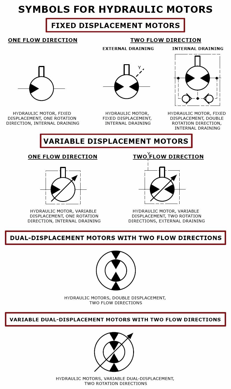
A hydraulic motor is a mechanical hydraulic actuator that converts hydraulic energy or hydraulic pressure into torque and angular displacement / rotation.
Hydraulic cylinder is a mechanical hydraulic actuator that converts hydraulic energy or hydraulic pressure into linear displacement. It consists of cylindrical barrel, piston and piston rod.
I. Pressure Relief Valve – They are designed to protect hydraulic system when pressure in the system increases beyond the specified design pressure or maximum working pressure. They are normally closed and it opens when the pressure exceeds a specified maximum value and diverts the pump flow back to reservoir or tank internally. They are located near hydraulic pump.
II. Pressure Reducing Valve – They are design to limit and maintain outlet pressure. They are normally open and closed if the pressure exceed beyond specified design pressure at outlet. They are located near hydraulic actuator.
IV. Counterbalance Valve – Counterbalance valves are used in hydraulic systems working with running-away or suspended load. They are designed to create backpressure at the return line of the actuator to prevent losing control over the load.
They control the returning flow in relation to the flow being directed into opposite side of the actuator. It is used in hydraulic system to influence the speed of hydraulic motor and hydraulic cylinder independent to the load (prevent running away).
It is a electro mechanically operated valve. The valve is control by electric current through a solenoid. The function of solenoid valve in hydraulic system is to shut off, distribute and release fluid.
The vector stencils library "Hydraulic pumps and motors" contains 74 symbols of hydraulic pump vector stencils, hydraulic motor symbols for engineering drawings of fluid power and hydraulic control systems.
Hydrostatic pumps are positive displacement pumps while hydrodynamic pumps can be fixed displacement pumps, in which the displacement (flow through the pump per rotation of the pump) cannot be adjusted, or variable displacement pumps, which have a more complicated construction that allows the displacement to be adjusted." [Hydraulic pump. Wikipedia]
"A hydraulic motor is a mechanical actuator that converts hydraulic pressure and flow into torque and angular displacement (rotation). The hydraulic motor is the rotary counterpart of the hydraulic cylinder.
Conceptually, a hydraulic motor should be interchangeable with a hydraulic pump because it performs the opposite function - much as the conceptual DC electric motor is interchangeable with a DC electrical generator. However, most hydraulic pumps cannot be used as hydraulic motors because they cannot be backdriven. Also, a hydraulic motor is usually designed for the working pressure at both sides of the motor.
Hydraulic pumps, motors, and cylinders can be combined into hydraulic drive systems. One or more hydraulic pumps, coupled to one or more hydraulic motors, constitutes a hydraulic transmission." [Hydraulic motor. Wikipedia]
The shapes example "Design elements - Hydraulic pumps and motors" was created using the ConceptDraw PRO diagramming and vector drawing software extended with the Mechanical Engineering solution from the Engineering area of ConceptDraw Solution Park.
Variable Displacement Pumps Market was valued at $3,322 million in 2016, and is projected to reach $4,478 million in 2023, growing at a CAGR of 4.4%. The substantial growth in automotive and manufacturing sector fosters the demand for variable displacement pumps. Variable displacement pump is a type of hydraulic pump that makes positive displacement. Variable displacement pumps are energy-efficient as compared to fixed displacement pumps as the pumps doesn"t require manual control and can control the amount of flow via valves that control speed of hydraulic actuators. Growth in construction industry is the major driver for the incremented demand for variable displacement pumps, which are used to have better control over large machine activities. Rising population and rapid urbanization would further contribute to the blooming construction industry, thus, the market for variable displacement pumps would also grow.
The global variable displacement pump market is segmented based on type, application, end-user and geography. Based on type, the market is categorized into vane pump and piston pump. Piston pumps would dominate the market throughout the analysis period owing to its wide volumetric & pressure efficiency range. Market by application comprises hydraulic and IC engine. Hydraulic pumps accounts for maximum market share due to increasing usage of hydraulic pumps in the manufacturing industry. The end-user segment include construction, agriculture, mining, automotive, material handling, oil & gas, water & waste water management, and others.
Variable displacement piston pumps market share is expected to grow at a considerable growth rate during the forecast period. It is a type of positive displacement pump in which number of pistons are arranged in a certain manner. It could be used as a stand-alone pump, an automotive air conditioning compressor, or a hydraulic motor.
Variable displacement pumps market for construction and water & waste water management industries is expected to grow at the significant growth rate during the forecast period. Water & waste water management is one of the crucial task of a city or a town, for which high-pressure, high torque, and highly efficient motors and pumps are required. Increase in innovations, high demands for high-performance, and efficient high-pressure pumps are expected to offer numerous growth opportunities for market expansion. Furthermore, the demand for hydropower energy and tidal energy is expected to drive the market growth. Increase in need for planned cities and towns and rise in standards of living in the developing countries are expected to fuel the market growth in this sector.
The Asia-Pacific variable displacement pumps market is expected to show significant growth in the near future, owing to development in infrastructure, availability of multiple manufacturing facilities, increase in population, significant growth in GDP in the developing countries, and increase in construction activities.
Technological advancements, increase in process automation, growth of oil & gas industry, and design upgradation of pumps & motors are expected to drive the market growth. Deep water and ultra-deep water reserves in Asia-Pacific are expected to contribute toward oil & gas production, and is expected to increase the sales of hydraulic pumps.
The key players profiled in this report are Bosch Rexroth AG, Parker Hannifin Corp., Danfoss A/S, Eaton Corporation, The Oilgear Company, Kawasaki Heavy Industries, Ltd., Yuken Kogyo Co., Hawe Hydraulics, Casappa SPA and Ranger Caradoc Hydraulics Ltd.
The study provides an in-depth analysis of the global variable displacement pumps market and current & future trends to elucidate the imminent investment pockets.


 8613371530291