
variable displacement hydraulic pump symbol free sample

The vector stencils library "Hydraulic pumps and motors" contains 74 symbols of hydraulic pump vector stencils, hydraulic motor symbols for engineering drawings of fluid power and hydraulic control systems.
Hydrostatic pumps are positive displacement pumps while hydrodynamic pumps can be fixed displacement pumps, in which the displacement (flow through the pump per rotation of the pump) cannot be adjusted, or variable displacement pumps, which have a more complicated construction that allows the displacement to be adjusted." [Hydraulic pump. Wikipedia]
"A hydraulic motor is a mechanical actuator that converts hydraulic pressure and flow into torque and angular displacement (rotation). The hydraulic motor is the rotary counterpart of the hydraulic cylinder.
Conceptually, a hydraulic motor should be interchangeable with a hydraulic pump because it performs the opposite function - much as the conceptual DC electric motor is interchangeable with a DC electrical generator. However, most hydraulic pumps cannot be used as hydraulic motors because they cannot be backdriven. Also, a hydraulic motor is usually designed for the working pressure at both sides of the motor.
Hydraulic pumps, motors, and cylinders can be combined into hydraulic drive systems. One or more hydraulic pumps, coupled to one or more hydraulic motors, constitutes a hydraulic transmission." [Hydraulic motor. Wikipedia]
The shapes example "Design elements - Hydraulic pumps and motors" was created using the ConceptDraw PRO diagramming and vector drawing software extended with the Mechanical Engineering solution from the Engineering area of ConceptDraw Solution Park.

The base symbol for the hydraulic pump (Figure 1) is actually quite simple. It starts with the standard circle and a directional arrow pointing out one end from within that circle. The solid-filled triangle makes this a hydraulic pump while pneumatic pumps (and most pneumatic symbols) are outlines only. There exist no other options for this particular pump symbol, which can be accurately described as a fixed displacement, unidirectional hydraulic pump.
It’s rare to see a pump in any orientation but North when reading schematics, and they are often paired below to a line terminating into the reservoir symbol, which I show just once. If multiple components such as filters, ball valves, accessories or even other pumps are used, the tank line can be widened as needed. Other designers prefer to show every tank line terminate into the same small symbol, while others will place a tank symbol right at every component requiring it, just is done in electrics with the ground symbol.
Unfortunately, and except for rare circumstances, there are no symbology differences between the type of pumps available. The symbols for a gear pump, a vane pump, a piston pump or any other type of physical configuration does not carry with it any symbolic difference, nor does it matter as you’ll find out by the end of this.
The second pump is not much different from the first, with the exception of the second black directional triangle, which informs us this pump can expel fluid from what would otherwise be the suction port. This is the symbol for a bi-rotational pump, which is rare outside of advanced mobile machinery, especially in the fixed displacement version as shown. Although a series of check valves could allow both ports to become either the tank or pressure lines, depending upon the direction of rotation, this is still a rare concept.
The third symbol in Figure 1 illustrates the very simplified version of the variable displacement, pressure compensated, unidirectional hydraulic pump. It includes the variable arrow across the entire symbol, explaining that the pump displacement can be modified. To the left is a smaller arrow, and as you may have picked up on from earlier symbol articles, it tells us the pump displacement varies automatically with pressure compensation. As a fan of ISO 1219 symbology, I don’t find this symbol visually pleasing, concise as it is.
My favourite symbol to express the pressure compensated pump is the smaller of the two symbols in Figure 2. This is a slightly more detailed example of the symbol I depicted in Hydraulic Symbology 101, and I’ve added colour to help with the explanation. Don’t worry about the scary looking object to the right, we’ll get to that shortly.
For this particular symbol of the pressure compensated pump, the shaft sticks out to the right, which can be attached to the square of a combustion engine prime mover symbol or the circular symbol of an electric motor. The semicircular arrow shows us the shaft rotates clockwise, or to the right since rotation direction is always observed from the vantage point of the shaft end.
The variable arrow bisects the pump symbol and of course tells us the pump is adjustable displacement. The method of displacement control is defined by the compound symbol attached to the pump’s left. Under the long rectangle is a spring with a variability arrow, which represents the pressure compensator spring, itself semi-enclosed and attached to the bottom of the pump’s variable arrow. Opposite the spring is a triangular input for pilot pressure, and this juxtaposition is intentional.
The orange pilot signal is taken directly from the red system pressure line exiting the pump, with the dashed orange line confirming it is indeed pilot energy. The spring setting fights with pilot pressure to infinitely and smoothly adjust the flow rate to match downstream pressure drop equal to the compensator setting. For example, if the setting is 3,000 psi, any downstream combination of load and flow-related pressure below 3,000 psi will see the spring maintain full displacement of the swashplate, producing full pump flow.
Moving along to the scary looking thing on the right, we have here the detailed breakdown of the variable displacement, pressure compensated, load-sensing, unidirectional hydraulic pump. You’ve likely seen this symbol before because the manufacturers prefer to show this level of detail, especially to differentiate advanced controls options like remoted compensation or horsepower control. This “load-sensing pump” will make sense to you shortly. I’ll warn that it will take some time and effort to understand this symbol as you methodically work through the rest of this article.
Starting with the pump (a), it has the diagonal variability arrow bisecting the circle and is attached to the rod ends of two cylinders. Cylinder (b) is the bias piston meant to force the pump to full displacement whenever possible, a task made easier by spring pushing the piston forward. Some pumps make do with only a strong spring, but this example is balanced with pilot energy. Affixed on the right is a tiny object with a variable arrow, which can be adjusted to move left or right within the cylinder. Not all pumps have this additional component, which is the minimum volume stop, preventing the bias piston from retracting fully, which subsequently prevents fully standby of the pump.
If you’re familiar with cylinder symbols, you’ll see that (c) also looks like a single acting cylinder with a stroke adjustor at the cap side. This is the control piston, which will always be a larger bore diameter than the bias piston. The control piston’s stroke adjustment is called the maximum volume stop and is used to modify the maximum displacement of the pump, convenient when you need a displacement between the two sizes available for the chosen pump. The two “cylinders” are attached by their rods to each other, and as one extends the other must retract and vice versa, and I’ll explain shortly why and how their battle develops.
Because all load sensing pumps must be pressure compensated, I’ll start with (d), which is the pressure compensator. Although it looks different, it is essentially a relief valve governing the control piston (c). It’s shown in its neutral condition, where it bleeds the chamber of the control piston (c) through orifice (e), orifice (f), and also through the other compensator (g) where it can choose any flow path directly to tank. Regardless of its flow path, pilot energy inside the control piston (c) is zero, so it loses the battle with the bias piston (b) and the pump is on full displacement pump at its highest rate.
The load sense compensator (g) looks much the same as the pressure compensator (d) and is similar in function except where it takes pilot energy and what it does with it afterward. As with the pressure compensator symbol (d), it is a 3-way, 2-position valve that is spring-offset with adjustable pressure settings for both. Each is supplemented with the parallel lines above and below both positional envelopes, and these lines tell us the valve is infinitely variable between the two positions.
The variable orifice at (j) could be any flow control, lever valve or proportional valve used to adjust flow (which creates backpressure when reduced) in the red system pressure line starting at the pump. You can see the node just after the pump outlet that combines system pressure with pilot lines supplying the bias piston and both compensators. Let’s first take the load sense compensator (g) out of the picture and describe the pressure compensator (d) and what occurs during operation.
When the pump fires up, and assuming all downstream directional valves are closed, the spring inside the bias piston (b) fully strokes the pump to max displacement. This immediately creates pressure in the work and pilot lines as fluid fills the plumbing with no exit strategy, and this rise in pressure at the pilot line at (d) forces the pressure compensator to shift to the right. The second pilot line attached to the top of compensator (d) allows pilot energy to enter through line (i) where it fills the control piston (c) rapidly. Because the control piston is larger bore than the bias piston, it wins the fight and moves the pump’s variable arrow to reduce displacement until the only flow is what is required to overcome leakage. The pump is on “standby.”
Now when a downstream directional valve is opened, a flow path is created that drops system pressure to below the setting of the (d) compensator, and it immediately succumbs to spring pressure and snaps back to near its neutral setting, opening the drain lines once again to tank. The orifices (e) and (f) dampen the motion of the compensator, preventing rapid oscillations, but the orifice also prevents pressure spikes into the pump’s case. They also ensure that pressure doesn’t decay from the control piston (c) when system pressure degrades rapidly for fractions of a second. Flow from the pump will be balanced by the opposing bias and control pistons to match downstream pressure drop at exactly the pressure compensator setting.
Finally, we look at the operation of the load sense compensator (g) shown on top. It also receives a pilot signal directly from the pump outlet, but you’ll see that it also gets a competing signal from the work line after the metering orifice. The pressure signal at (g) compares the combined effort of the spring value and the load-sense pilot signal just before (h). The setting of the pressure compensator (d) is much higher than the setting of the load sense compensator (g), which is set to create reasonable pressure drop across (j). If the (d) compensator is set to 3,000 psi, it’ll only see this pressure on standby or max load pressure, while the (g) compensator might be set to 300 psi, where it measures pressure drop across (j) valve.
Typically a load sense circuit will have multiple orifices in a load sense network all feeding back a pilot signal to the load sense compensator (g), where it picks the highest pressure signal and meters the pump’s flow to match that pressure differential and provides just enough flow to satisfy the desired flow rate at the desired work pressure plus the pressure of the load sense compensator’s spring value. For example, if load pressure is 1,000 psi, the pump will hold pressure at 1,300 psi, providing the extra 300 psi just to create flow across the metering valve (j).
This symbol shows you that no matter the initial feeling of complexity, breaking down any schematic thoughtfully reveals its purpose of design. I fell in love with hydraulics when I learned about the load sensing concept. That just using columns of fluid pressure to create an efficient supply and demand scenario to satisfy many downstream actuators with essentially the exact flow and pressure they need for the job, and little more, I found exhilarating.

I. Fixed Displacement Pump – These pump has a set flow rate means every stroke of the motor moves same amount of fluid. Fixed displacement pumps are perfect for single jobs that to be repeated indefinitely over long periods of time. There are three types of fixed displacement pump : Gear Pump, Gerotor Pump, Screw Pump.
II. Variable Displacement Pump – In Variable displacement pumps flow rate and outlet pressure can be changed as the pump operates. They are used to power a wider variety of tool, but require more expense and more attention. There are four types of variable displacement pump: Bent Axis Pump, Axial Piston Pump, Radial Piston Pump, Rotary Vane Pump.
A hydraulic motor is a mechanical hydraulic actuator that converts hydraulic energy or hydraulic pressure into torque and angular displacement / rotation.
Hydraulic cylinder is a mechanical hydraulic actuator that converts hydraulic energy or hydraulic pressure into linear displacement. It consists of cylindrical barrel, piston and piston rod.
I. Pressure Relief Valve – They are designed to protect hydraulic system when pressure in the system increases beyond the specified design pressure or maximum working pressure. They are normally closed and it opens when the pressure exceeds a specified maximum value and diverts the pump flow back to reservoir or tank internally. They are located near hydraulic pump.
II. Pressure Reducing Valve – They are design to limit and maintain outlet pressure. They are normally open and closed if the pressure exceed beyond specified design pressure at outlet. They are located near hydraulic actuator.
IV. Counterbalance Valve – Counterbalance valves are used in hydraulic systems working with running-away or suspended load. They are designed to create backpressure at the return line of the actuator to prevent losing control over the load.
They control the returning flow in relation to the flow being directed into opposite side of the actuator. It is used in hydraulic system to influence the speed of hydraulic motor and hydraulic cylinder independent to the load (prevent running away).
It is a electro mechanically operated valve. The valve is control by electric current through a solenoid. The function of solenoid valve in hydraulic system is to shut off, distribute and release fluid.

It wasn’t until the beginning of the industrial revolution when a British mechanic named Joseph Bramah applied the principle of Pascal’s law in the development of the first hydraulic press. In 1795, he patented his hydraulic press, known as the Bramah press. Bramah figured that if a small force on a small area would create a proportionally larger force on a larger area, the only limit to the force that a machine can exert is the area to which the pressure is applied.
Hydraulic systems can be found today in a wide variety of applications, from small assembly processes to integrated steel and paper mill applications. Hydraulics enable the operator to accomplish significant work (lifting heavy loads, turning a shaft, drilling precision holes, etc.) with a minimum investment in mechanical linkage through the application of Pascal’s law, which states:
The principle of Pascal’s law is realized in a hydraulic system by the hydraulic fluidthat is used to transmit the energy from one point to another. Because hydraulic fluid is nearly incompressible, it is able to transmit power instantaneously.
The purpose of the hydraulic reservoir is to hold a volume of fluid, transfer heat from the system, allow solid contaminants to settle and facilitate the release of air and moisture from the fluid.
The hydraulic pump transmits mechanical energy into hydraulic energy. This is done by the movement of fluid which is the transmission medium. There are several types of hydraulic pumps including gear, vane and piston. All of these pumps have different subtypes intended for specific applications such as a bent-axis piston pump or a variable displacement vane pump. All hydraulic pumps work on the same principle, which is to displace fluid volume against a resistant load or pressure.
Hydraulic valves are used in a system to start, stop and direct fluid flow. Hydraulic valves are made up of poppets or spools and can be actuated by means of pneumatic, hydraulic, electrical, manual or mechanical means.
Hydraulic actuators are the end result of Pascal’s law. This is where the hydraulic energy is converted back to mechanical energy. This can be done through use of a hydraulic cylinder which converts hydraulic energy into linear motion and work, or a hydraulic motor which converts hydraulic energy into rotary motion and work. As with hydraulic pumps, hydraulic cylinders and hydraulic motors have several different subtypes, each intended for specific design applications.
There are several components in a hydraulic system that are considered vital components due to cost of repair or criticality of mission, including pumps and valves. Several different configurations for pumps must be treated individually from a lubrication perspective. However, regardless of pump configuration, the selected lubricant should inhibit corrosion, meet viscosity requirements, exhibit thermal stability, and be easily identifiable (in case of a leak).
There are many variations of vane pumps available between manufacturers. They all work on similar design principles. A slotted rotor is coupled to the drive shaft and turns inside of a cam ring that is offset or eccentric to the drive shaft. Vanes are inserted into the rotor slots and follow the inner surface of the cam ring as the rotor turns.
The vanes and the inner surface of the cam rings are always in contact and are subject to high amounts of wear. As the two surfaces wear, the vanes come further out of their slot. Vane pumps deliver a steady flow at a high cost. Vane pumps operate at a normal viscosity range between 14 and 160 cSt at operating temperature. Vane pumps may not be suitable in critical high-pressure hydraulic systems where contamination and fluid quality are difficult to control. The performance of the fluid’s antiwear additive is generally very important with vane pumps.
As with all hydraulic pumps, piston pumps are available in fixed and variable displacement designs. Piston pumps are generally the most versatile and rugged pump type and offer a range of options for any type of system. Piston pumps can operate at pressures beyond 6000 psi, are highly efficient and produce comparatively little noise. Many designs of piston pumps also tend to resist wear better than other pump types. Piston pumps operate at a normal fluid viscosity range of 10 to 160 cSt.
There are two common types of gear pumps, internal and external. Each type has a variety of subtypes, but all of them develop flow by carrying fluid between the teeth of a meshing gear set. While generally less efficient than vane and piston pumps, gear pumps are often more tolerant of fluid contamination.
Internal gear pumps produce pressures up to 3000 to 3500 psi. These types of pumps offer a wide viscosity range up to 2200 cSt, depending on flow rate and are generally quiet. Internal gear pumps also have a high efficiency even at low fluid viscosity.
External gear pumps are common and can handle pressures up to 3000 to 3500 psi. These gear pumps offer an inexpensive, mid-pressure, mid-volume, fixed isplacement delivery to a system. Viscosity ranges for these types of pumps are limited to less than 300 cSt.
Today’s hydraulic fluids serve multiple purposes. The major function of a hydraulic fluid is to provide energy transmission through the system which enables work and motion to be accomplished. Hydraulic fluids are also responsible for lubrication, heat transfer and contamination control. When selecting a lubricant, consider the viscosity, seal compatibility, basestock and the additive package. Three common varieties of hydraulic fluids found on the market today are petroleum-based, water-based and synthetics.
Petroleum-based or mineral-based fluids are the most widely used fluids today. These fluids offer a low-cost, high quality, readily available selection. The properties of a mineral-based fluid depend on the additives used, the quality of the original crude oil and the refining process. Additives in a mineral-based fluid offer a range of specific performance characteristic. Common hydraulic fluid additives include rust and oxidation inhibitors (R&O), anticorrosion agents, demulsifiers, antiwear (AW) and extreme pressure (EP) agents, VI improvers and defoamants. Additionally, some of these lubricants contain colorful dyes, allowing you to easily identify leaks. Because hydraulic leaks are so costly (and common), this minor characteristic plays a huge role in extending the life of your equipment and saving your plant money and resources.
Elevated temperatures cause the water in the fluids to evaporate, which causes the viscosity to rise. Occasionally, distilled water will have to be added to the system to correct the balance of the fluid. Whenever these fluids are used, several system components must be checked for compatibility, including pumps, filters, plumbing, fittings and seal materials.
When choosing a hydraulic fluid, consider the following characteristics: viscosity, viscosity index, oxidation stability and wear resistance. These characteristics will determine how your fluid operates within your system. Fluid property testing is done in accordance with either American Society of Testing and Materials (ASTM) or other recognized standards organizations.
Viscosity (ASTM D445-97) is the measure of a fluid’s resistance to flow and shear. A fluid of higher viscosity will flow with higher resistance compared to a fluid with a low viscosity. Excessively high viscosity can contribute to high fluid temperature and greater energy consumption. Viscosity that is too high or too low can damage a system, and consequently, is the key factor when considering a hydraulic fluid.
Viscosity Index (ASTM D2270) is how the viscosity of a fluid changes with a change in temperature. A high VI fluid will maintain its viscosity over a broader temperature range than a low VI fluid of the same weight. High VI fluids are used where temperature extremes are expected. This is particularly important for hydraulic systems that operate outdoors.
Aside from these fundamental characteristics, another property to consider is visibiilty. If there is ever a hydraulic leak, you want to catch it early on so you don"t damage your equipment. Opting for adyed lubricant can help you spot leaks quickly, effectively saving your plant from machine failure.
When selecting lubricants, ensure that the lubricant performs efficiently at the operating parameters of the system pump or motor. It is useful to have a defined procedure to follow through the process. Consider a simple system with a fixed-displacement gear pump that drives a cylinder (Figure 2).
Collect all relevant data for the pump. This includes collecting all the design limitations and optimum operating characteristics from the manufacturer. What you are looking for is the optimum operating viscosity range for the pump in question. Minimum viscosity is 13 cSt, maximum viscosity is 54 cSt, and optimum viscosity is 23 cSt.
Check the actual operating temperature conditions of the pump during normal operation. This step is extremely important because it gives a reference point for comparing different fluids during operation. Pump normally operates at 92ºC.
Using the manufacturer’s data for the pump’s optimum operating viscosity, find the value on the vertical viscosity axis of the chart. Draw a horizontal line across the page until it hits the yellow viscosity vs. temperature line of the lubricant. Now draw a vertical line (green line, Figure 5) to the bottom of the chart from the yellow viscosity vs. temperature line where it is intersected by the horizontal optimum viscosity line. Where this line crosses, the temperature axis is the optimum operating temperature of the pump for this specific lubricant (69ºC).
Repeat Step 8 for maximum continuous and minimum continuous viscosities of the pump (brown lines, Figure 5). The area between the minimum and maximum temperatures is the minimum and maximum allowable operating temperature of the pump for the selected lubricant product.
Find the normal operating temperature of the pump on the chart using the heat gun scan done in Step 2. If the value is within the minimum and maximum temperatures as outlined on the chart, the fluid is suitable for use in the system. If it is not, you must change the fluid to a higher or lower viscosity grade accordingly. As shown in the chart, the normal operating conditions of the pump are out of the suitable range (brown area, Figure 5) for our particular lubricant and will have to be changed.
The purpose of hydraulic fluid consolidation is to reduce complexity and inventory. Caution must be observed to consider all of the critical fluid characteristics required for each system. Therefore, fluid consolidation needs to start at the system level. Consider the following when consolidating fluids:
Hydraulic systems are complicated fluid-based systems for transferring energy and converting that energy into useful work. Successful hydraulic operations require the careful selection of hydraulic fluids that meet the system demands. Viscosity selection is central to a correct fluid selection.

Hydraulics engineers regularly encounter these diagrams, but these symbols can be daunting to interpret if you have limited experience with schematics and the fluid power industry.
On this page, Carr Lane ROEMHELD provides a comprehensive table outlining the definitions of each symbol used in a hydraulic diagram. Engineers can use this page as a reference to determine common schematic symbols used in fluid power, hydraulics, pneumatics, diagrams and circuits.

A radial piston pump is a form of hydraulic pump. The working pistons extend in a radial direction symmetrically around the drive shaft, in contrast to the axial piston pump.
When filling the workspace of the pumping pistons from "inside" (e.g., over a hollow shaft) it is called an inside impinged (but outside braced) radial piston pump (picture 1). If the workspace is filled from "outside" it"s called an outside impinged radial piston pump (but inside braced) (picture 2).
The outer ring for bracing of the pumping pistons is in eccentric position to the hollow shaft in the center. This eccentricity determines the stroke of the pumping piston.
The piston starts in the inner dead center (IDC) with suction process. After a rotation angle of 180° it is finished and the workspace of the piston is filled with the moved medium. The piston is now in the outer dead center (ODC). From this point on the piston displaces the previously sucked medium in the pressure channel of the pump.
A disadvantage is the bigger radial dimensions in comparison to the axial piston pump, but it could be compensated with the shorter construction in axial direction.
Due to the hydrostatically balanced parts it is possible to use the pump with various hydraulic fluids like mineral oil, biodegradable oil, HFA (oil in water), HFC (water-glycol), HFD (synthetic ester) or cutting emulsion. That implies the following main applications for a radial piston pump:
"Variable Stroke Radial Piston Pump", T.S. Patriot State Engineering Manual, Massachusetts Maritime Academy, 1996, pp. 234–241, retrieved 14 September 2022

In the world of manufacturing and industry, pumps play a crucial role in keeping operations running smoothly. There are different types of pumps available, and two common ones are hydraulic pumps and vacuum pumps. Since it is not always easy to choose the right equipment in front of a multitude of manufacturers, we have produced several buying guides with tips and recommendations to help you make the right purchasing decision.
A pump is a device used to move fluids, such as liquids or gases, from one place to another. It works by creating pressure that drives the fluid through a system of pipes or hoses. The type of pump used depends on the application and the fluid being moved.
There are different types of pumps available. Understanding what they do and how they work can help businesses make informed decisions about their operations.
A pump is a mechanical tool that converts motor energy into hydraulic energy in order to transport fluids. When selecting a pump, the first aspect to consider is the type of fluid being transported. It is essential to factor in the technical properties of the fluid since they determine the appropriate pump to use. To properly size the pump and determine its operating point, it is necessary to know various parameters of the system, such as flow rate, suction head, discharge head, and head losses. This guide provides an overview of the primary types of pumps and their typical applications.
For businesses operating in industries that require the use of heavy machinery, a hydraulic pump is an essential component in maintaining smooth and efficient operations.
A hydraulic pump is responsible for circulating hydraulic fluid like oil, at high pressure through pipes to activate hydraulic actuators, such as cylinders or motors. By utilizing this pressurized fluid, the hydraulic actuators are able to produce linear or rotary motion, generating the necessary force and power required for various applications.
Given the critical role of a hydraulic pump in a hydraulic circuit, selecting the appropriate pump is crucial to ensure optimal performance and longevity. A well-chosen pump can enhance the system’s efficiency, and reduce energy consumption and maintenance costs.
A vacuum pump is a device that extracts air or gas from a tank to create a partial or complete vacuum within a given system. This is achieved through the gradual reduction of pressure within the enclosed space, which allows air to be drawn into the pump. The pump then extracts the aspirated gaseous molecules from the system and releases them into the ambient air or another tank.
In various industrial sectors, such as laboratories, the medical industry, food packaging, and the chemical industry, a vacuum pump is a critical tool that enables efficient and effective operations.
There are several types of vacuum pumps available, including diaphragm pumps, rotary vane pumps, and scroll pumps. Each type has its own advantages and disadvantages, and the selection of the appropriate vacuum pump will depend on the specific requirements of the application.

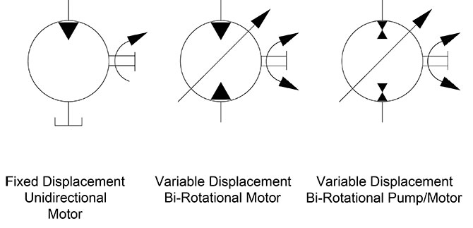
The symbols for hydraulic motors, especially in their simpler forms, are very similar to those of hydraulic pumps. If you haven’t already had the chance, see my article on pumps symbols here first. The directional arrow that points inward to accept fluid power energy is the primary difference between pump and motor symbols, and in Figure 1 you can see the simple fixed displacement, unidirectional hydraulic motor.
The shaft symbol may or not be present in a schematic, as with the rotation direction arrow. The shaft symbol may even include a symbolic depiction of the device being rotated, such as a wheel or a drum. Always remember although there are ANSI and ISO standards for drawing schematics, the engineer or designer may draw a circuit as they wish, so you may come encounter modified or unknown symbols.
The second symbol stands for the variable displacement bi-rotational motor. The dark triangle depicting the direction of hydraulic energy is now diametrically opposed to indicate the motor takes fluid from both ports. If it’s not plain enough already, the shaft has bidirectional rotation arrows bent around the shaft as well. You will also notice both ports are now open to flow rather than one that terminates at the tank as the first symbol. Finally, the tell-tale variable arrow dissects the circle, showing us the motor has a variable displacement, although telling us nothing of how that might occur.
The final symbol of Figure 1 is just like the last, save for two slight differences. The dark flow triangles are stacked atop each other and in opposing directions. This configuration represents a unit capable of both pumping and absorbing hydraulic energy, or more succinctly, the variable displacement, bi-rotational pump-motor. Used in few locations other than a drive application, such as the clever hydraulic hybrid applications for dump trucks or loaders, where stopping energy can be fed back into the system and stored in an accumulator.
Motor controls, aside from hydrostatic drives, are not usually overly complicated. The variable displacement, bi-rotational hydraulic motor shown on the left in Figure 2 has everything the earlier one did save the case drain line. Being a simplified symbol, as most fluid power symbols are, it gives you basic details on what it does but doesn’t provide the scope of performance, the method of construction or dimensional envelope. The apparent mess of lines and shapes to the right does, in fact, break down the method of operation, at the very least.
By this point, the motor symbol needs no explanation, so we’ll skip that part. Denotations (a) and (b) are the work ports, which are the common characters used to denote work ports, even on the directional valves as well. Each work port terminates not only at the motor ports but also at the (c) component, which is called a shuttle valve. The shuttle valve is a 3-port check valve that always provides a flow path for the higher of the two work ports. In this case, work pressure is coming from port (a), so the check valve shuts off port (b) due to pressure differential.
The part looking like a spring-retracted cylinder can be considered as such, and this is the object primarily responsible for controlling motor displacement, which in turn will change torque and speed. The spring keeps the bias piston retracted, providing the motor with full displacement until told otherwise. How it gets told otherwise is through the pilot valve operated 3/2 valve shown at (g). In its neutral state, it provides a flow path to tank for the bias piston so that motor’s tendency is full flow.
When a pilot valve somewhere upstream of (x) is activated, fluid enters the pilot chamber of the 3/2 valve (g), where it shifts to provide pilot energy sourced from the shuttle valve (c) to the bias piston. The bias piston now shifts fully, reducing the swashplate angle to reduce flow. Just how low the displacement goes is dictated by the tiny stroke limiter (e), which is just an adjustment screw that prevents the swashplate from reducing its angle further. The orifice at (f) is used to dampen the actions of the pilot energy working to move the bias piston. Without this orifice, the pump may shift too quickly or be susceptible to work pressure fluctuations coming from ports (a) or (b).
A motor such as this might be used as a two-speed transmission. The full flow, large angle of the swashplate provides higher torque yet slower speed while shifting the pilot valve energizes the bias piston, reducing swashplate angle to reduce displacement, therefore increasing speed while lowering torque. The shuttle valve ensures pilot energy is available regardless of motor rotation direction, however, it should be noted that the pilot valve could instead be a mechanical lever or some sort of torque limiting valve.
The standard hydraulic cylinder depicted way back in Hydraulic Symbology 102 is as clean and pure as one can ask, but you’d be surprised at the number of ways a cylinder can be drawn (and therefore constructed). Where possible in these examples, I’ve made a wide piston rather than the single line in previous examples, and also shown the rod as a long rectangle as well. For some of these examples, it is required to make sense of the symbol, so I used it across the board for the purpose of consistency.
The Double Rod Cylinder is quite easy to understand. Instead of a single head, cap and rod, this component now has two rods joined by a common piston and is then guided through two heads. This symbol looks very much like its construction, at least from the point of view of the piston rod assembly.
The Spring Retract Cylinder is another that takes little to decode. It starts by looking much like a regular cylinder symbol, but now with a giant spring placed in the annular (rod side) area of the cylinder. Imagine now that pressure is applied to the cap side and the piston starts to extend. As it does, the spring compresses in an attempt to once again retract the cylinder without the help of rod side hydraulic energy. When pressure is relieved from the cap side, the cylinder retracts using the compressed energy stored within the spring.
A ram is a hydraulic cylinder with one fluid port on a tube that is stuffed with a rod. The rod is typically a large diameter relative to the body because the base of the rod also performs as the piston. So if your ram has a 4-in. rod, then your ram has a 4-in. piston. The port can be drawn nearly anywhere on a ram because fluid coming in the side will still extend the cylinder, as fluid pressurizing the rod radially has no effect on it.
When a load of a dump truck or other piece of machinery employing a telescopic cylinder goes over center (meaning past its pivot point), the load then pulls the rod out further. Gravity is no longer able to retract the cylinder and lower the dump body, so a Double Acting Telescopic cylinder is required. It’s very much like the single-acting example, but now with actual pistons and a complicated porting network. The symbol shows a piston rod within a piston rod within a piston rod, which fairly well represents how it is constructed.
Motors and actuators in real applications rarely employ some of the options shown, but they’re important to know so you not only understand schematics that may come across your desk. As well, know what components are available by way of their symbol allows for creativity and diversity in your schematic creations.


 8613371530291