
wagner loader hydraulic pump factory
The specification of the patent in suit states that it relates to "hanger bracket pump mountings for tractors equipped with loader frames." The specification refers to apparatus in which "the hydraulic pump which powers the boom and other tractor attachments is mounted on the base or loader frame of the tractor" and further states:
"* * * This pump receives power from the engine drive shaft through an extension shaft having a flexible coupling to accommodate for movment of the frame respecting the tractor when the frame is stressed under load or otherwise. In actual practice the coupling is frequently damaged by excessive frame movement, and it has been a source of equipment breakdown.
"It is the object of the present invention to re-locate the pump and to mount it directly from the tractor and, specifically, upon the hanger plate to which the underslung U-shaped member of the loader frame is connected. The re-located pump, accordingly, receives direct support from the tractor and is not subject to stresses imposed upon the loader.
"The invention consists in mounting the loader system pump in fixed relation to the tractor and in alignment with the tractor drive shaft and upon a platform specially provided on the hanger plate aforesaid. In one embodiment of the invention the U-shaped member of the loader frame is rigidly connected to the bracket to transmit bending stresses in the loader frame directly to the tractor. In another embodiment of the invention the U-shaped member of the loader frame is pivotally connected to the hanger bracket to relieve the tractor from such bending stresses."
"1. A hanger plate for attachment to a tractor having a loader frame subject to bending stress and a forwardly projecting drive shaft, said plate being provided with means for releasably mounting it on the tractor, a platform forwardly extending from said plate and mounting means on the platform to which a pump may be secured through said platform and hanger plate directly to said tractor and in alignment with said tractor drive shaft, said hanger plate further comprising means for mounting said loader frame on the tractor independent of said pump mounting means whereby bending stresses imposed on the loader frame are transmitted directly to the tractor without affecting the pump and its alignment with the tractor drive shaft.
"12. In combination, a tractor having a forwardly projecting power take-off shaft, a loader frame and a hydraulic system requiring a pump for its operation, means supporting the loader frame detachably on the tractor and including a bracket in rigid connection with the front of the tractor and having a releasable connection with the loader frame, certain portions of the frame being yieldable for relative movement respecting the bracket, a pump for said hydraulic system provided with a rigid mounting to said bracket independently of yieldable portions of the frame and having a drive shaft coupled with the tractor power take-off shaft, and hydraulic connections carried by the frame and having inlet and outlet connection with the pump and flexible to accommodate such yielding without affecting the pump or coupling.
"21. In a device of the character described, a combined tractor loader frame hanger and mounting for a pump, comprising a plate, means for connecting the plate to the tractor, a platform projecting forwardly from said plate and comprising means upon which said pump may be mounted, said plate being further provided with depending means for the connection thereto of said loader frame."
It is obvious that Claim 2 is intended to embrace, in addition to the elements set forth in Claim 1, an element not included in Claim 1, to wit, means for rigidly mounting the loader to the hanger plate.
It is obvious that Claim 3 is intended to embrace, in addition to the elements set forth in Claim 1, an element not included in Claim 1, to wit, means for pivotally mounting the loader to the hanger plate.
It is obvious that Claim 15 is intended to embrace, in addition to the elements set forth in Claim 12, an element not included in Claim 12, to wit, a rigid connection of the loader frame to the bracket.
And it is obvious that Claim 16 is intended to embrace, in addition to the elements set forth in Claim 12, an element not included in Claim 12, to wit, a pivotal connection of the loader frame to the bracket.
It follows that neither Claim 1 nor Claim 12 embraces either the element of rigid mounting of the loader frame on the plate or the element of pivotal mounting of the loader frame on the plate. That is also true of Claim 21.
In the commercial device of the patent in suit, the plate is rigidly attached to the front portion of the frame of the tractor. A bracket which embraces a platform is welded to the plate. The pump is mounted on the platform, with its drive shaft in alignment with the drive shaft of the tractor motor. The drive shaft of the tractor motor is extended and is releasably connected with the drive shaft of the pump. An underslung U-shaped portion of the loader frame, which extends beneath the tractor body, embraces a bracket welded to such U-shaped portion and such bracket is bolted to the plate by three bolts. The holes in the bracket and plate through which the three bolts extend are larger than the bolts, so as to permit a limited movement of the loader frame relative to the plate. Clearly, the bolt mounting is not a pivotal mounting nor the equivalent of a pivotal mounting.
Each of the alleged infringing devices mounts the pump on a bracket rigidly attached by bolts to the front portion of the tractor frame and each employs an extended drive shaft of the motor connected to and in alignment with the drive shaft of the pump. In the Shawnee device the transverse section of the U-shaped member is slidably mounted in a channel. The channel is composed of three plates welded together at right angles, leaving the front side open. The channel is mounted on a bracket which is attached to the front end of the motor frame and which bracket also carries the pump.
In the alleged infringing device of Henry, a plate is rigidly mounted on the front portion of the tractor frame, to which is attached the bracket which carries the pump. The transverse section of the U-shaped portion of the loader frame is attached to the plate by two pivots, one near each end of such transverse section. The pivots are formed by a sleeve attached to the bracket and a round, pinlike member with a head which extends through the transverse section into the sleeve. It will thus be seen that both infringing devices have means by which the U-shaped portion of the frame may move relative to the member to which it is attached.
The specification describes means for rigidly connecting the U-shaped member of the loader frame to the plate or bracket attached to the front portion of the tractor frame. It also describes means for pivotally connecting the U-shaped portion of the loader frame to the plate or bracket attached to the front portion of the tractor. Other than the pivotal mounting, the specification wholly fails to describe any method, manner or means of mounting the U-shaped portion of the loader frame, or any other portion of the loader frame, on the bracket or plate attached to the front portion of the tractor frame, so as to provide yieldability of the frame for relative movement respecting the bracket or plate. As stated above, neither Claim 1 nor 12 embraces the element of a pivotal mounting of the loader frame on the plate or bracket. That is likewise true of Claims 13 and 21.
3. Means supporting the loader frame detachably on the tractor and including a bracket in rigid connection with the front end of the tractor and having a releasable connection with the loader frame;
4. A pump for the hydraulic system, provided with a rigid mounting to said bracket independently of yieldable portions of the loader frame and having a drive shaft coupled with the tractor power take off shaft;
5. Hydraulic connections carried by the loader frame and having inlet and outlet connections with the pump and flexible to accommodate such yielding without affecting the pump or coupling.
The applicant for the patent also undertook to include an additional element in Claim 12 by use of the following language: "Certain portions of the (loader) frame being yieldable for relative movement respecting the bracket."
It follows that we must exclude from consideration of the claims here in suit any means for flexibly mounting the U-shaped portion of the loader frame on the plate or bracket by pivots or by the use of bolts which are smaller than the holes through which they extend.
The narrow question then presented is whether the concept which embraces the plate rigidly attached to the front portion of the tractor frame, the bracket attached to such plate, the platform on the bracket, the hydraulic pump mounted on such platform, with its shaft in alignment with and connected to the extended shaft of the motor, and the mounting of the U-shaped portion of the loader frame on the bracket or plate, arose to the dignity of invention.
The proof established that the invention covered by the patent was conceived by Werner and Wagner, Iron Works" assignors, shortly before May 15, 1951. Prior to that date, Iron Works was manufacturing the Simmonds loader frame for Dearborn Motors Corporation, the owner of Simmonds Patent No. 2,495,144, issued January 17, 1950, and was also manufacturing loader frames for other customers. Iron Works mounted the hydraulic pump on the front end of the loader frame. Stresses generated by the loader frame caused excessive breakage of the pump drive shaft, with resultant injury to other portions of the equipment. Werner and Wagner, executives of Iron Works, undertook to design a loader frame and pump that would solve the problem. The experimental work was done by employees of Iron Works under the direction of Werner and Wagner and resulted in a device substantially like the commercial device of the patent in suit, described above. The new loader frame and pump were placed on the market prior to May 15, 1951, and the first work was done on the manufacture of the commercial device about May 15, 1951. The experimental device manufactured under the direction of Werner and Wagner and the commercial devices employed 5/8 inch bolts and 11/16 inch holes to mount the transverse section of the U-shaped member of the loader frame on the plate.
The reason for the failure to describe such method of mounting in the specification or elsewhere in the patent is not entirely clear. Werner testified that they did not conceive the idea of employing bolts smaller than the holes through which they extended, but that such clearance was in the holes from their initial construction. It may be, therefore, that they did not deem that type of mounting as important when the patent was applied for. However, Mr. Werner expressed the opinion in his testimony that the movement made possible by such type of mounting contributed "to the absorption of the stresses and strains" generated by the loader. Werner admitted that there was no suggestion in the patent for a mounting of the transverse section on the plate by means of bolts smaller than the holes through which they extended and that on the contrary the patent suggested a rigid mounting of the transverse section of the loader frame on the plate.
The concept of mounting the hydraulic pump on a bracket rigidly attached to the front portion of the frame of the tractor, with the pump drive shaft in alignment with and connected to an extension of the drive shaft of the tractor was not new, when in 1951 Werner and Wagner conceived the device of the patent in suit. It was disclosed by Machin in his Patent No. 2,479,048, applied for October 16, 1946, and granted August 16, 1949, assigned to Ottawa Steel Products, Inc. In his specifications Machin stated, "I provide a pump supported on the tractor frame by brackets by bolts or the like. A shaft extends through a bushing secured to the bracket members by bolts or the like and engages within a connecting collar on the end of the extension shaft having a universal joint connection with the crank shaft of the tractor * * *."
In Drawing No. 5 of his patent, Machin illustrates a pump mounted on a bracket, which bracket is rigidly attached to the frame of the tractor and an extended drive shaft of the pump in alignment with the crank shaft of the tractor and the two shafts connected by a universal joint.
Moreover, in 1946 Ottawa Steel Products was engaged in the manufacture of front end loaders for farm tractors in which the hydraulic pump was mounted on the loader frame and experienced shaft breakage resulting from shaft misalignment caused by stresses generated by movements of the loader frame.
To meet that problem the engineers of Ottawa Steel Products in 1947, following the teaching of Machin, mounted the pump on the front portion of the tractor frame by means of a "pump plate strut support assembly," rigidly mounted the loader frame on the plate support assembly, positioned the pump so its drive shaft was in line with the drive shaft of the motor and connected the two drive shafts by a flexible coupling. They thus solved as early as 1947 the problem of pump drive shaft breakage and resulting damage caused by misalignment of the pump drive shaft.
Thus it will be seen that the only novelty in the device conceived and built by Werner and Wagner was the mounting of the loader frame on the plate by means of bolts that were smaller in diameter than the holes through which they extended, thus permitting the limited movement by the loader frame relative to the plate — a mounting not described nor validly claimed in the patent. Moreover, we are of the opinion that it would be obvious to an ordinary mechanic, skilled in the art, that the problem of pump crank shaft breakage resulting from mounting the pump on the loader frame and the transmission of loader frame stresses to the pump crank shaft would be solved by rigidly mounting the pump on the front portion of the tractor frame, mounting the transverse section of the U-shaped member of the frame on such tractor frame and aligning the pump drive shaft and the tractor drive shaft and connecting them together, so that stresses which would cause the motor drive shaft to move would cause the same movement of the pump drive shaft and thus keep the two drive shafts in fixed relation, whereby misalignment of the shafts would be avoided.
"This application is a continuation-in-part of our co-pending application, Serial No. 357,284 filed May 25, 1953, now abandoned, and entitled `Pump Mounting.""
We do not pass on the question not raised by counsel, but which lurks in the record, as to whether Werner and Wagner were not entitled to the patent, because the device of the patent in suit was "in public use or on sale in this country, more than one year prior to the date of the application for patent. * * *" See 35 U.S.C., 1946 Ed., § 31 and 35 U.S.C.A. § 102.
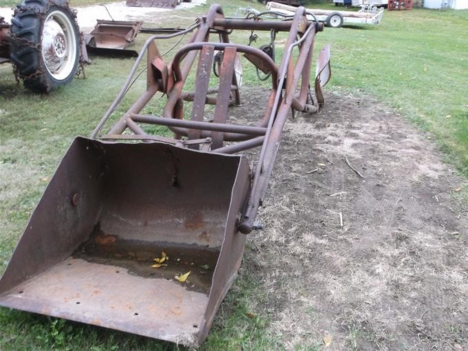
We have acquired my grandfathers 1952 TO 30 Ferguson tractor and some of the implements he had. We are trying to go through it and do oil changes etc. on the tractor. We have the operator and service manuals for the tractor itself. However it has a WAGNER WM4 loader on it & we can not find any manuals on it to do the fluid and filter changes on it and it’s running system. Do you have any sources for us to find this information?
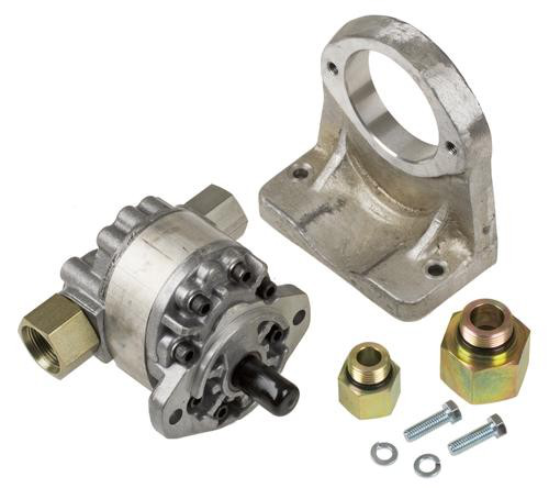
I am attaching a copy of the manual for the Wagner WM4 loader and a link to a generic manual from Wagner that covers most of their loaders including the W-3 and the WM-3. This manual refers to installing the loader on Ford tractors but the information on the loader is the same.
There is a strainer/filter, near the hydraulic pump, that should be cleaned periodically. The manual says to use Wagner Hydraulic oil. Wagner brand oil is no longer available but there are substitutes. From the information I have been able to gather it appears that you should be able to operate your loader on either regular motor oil in the appropriate weight for the season, or on Automatic Transmission fluid.
A manual for a Ford Dearborn 19-22 loader which is nearly identical to the Wagner and I believe was made for Ford by Wagner Iron Works says to use: 30 wt motor oil in temps of 90 degrees and above 20 wt motor oil in temps of 32 degrees to 90 degrees 20W wt motor oil in temps of 10 degrees to 32 degrees 10wt motor oil in temps of -10 degrees to +10 degrees 20 wt The 20W oil would be the best general use weight to use — automatic transmission fluid would be about the same.
I would suggest draining all the oil in the system before you add automatic transmission fluid as there are different types of automatic transmission fluid, which is usually red, and mixing them can cause problems. Similarly, not knowing what the existing oil is in the loader, I would suggest draining it as well before refilling with one of the above motor oils.
To drain the system you should leave the drain plug out or the return line off at the pump for at least 24 hours. I am sending you the instructions for filling and purging the air from the hydraulic system. I did locate a set of instructions for mounting your loader on a TO-30 and can send them to you if you like.
Hydraulics are critical to the optimal functionality of your Caterpillar heavy equipment machines. Hydraulics, at its core, is the use of liquids to do work, or to cause a movement. For heavy equipment, hydraulics are what allow a crane to lift heavy objects and a bucket to be moved by a loader. An engine or a motor powers a pump that then pressurizes the hydraulic fluid. This fluid that is now under pressure passes through hydraulic tubes or hoses to move objects. When you are through with the movement, the fluid reverses course and passes through a filter and back to the pump where it is ready to be used again.
Hydraulic hose rebuilding is the process of restoring broken tubes or hoses so that you can keep performing work for you or your client. These tubes, even though they are usually reinforced with metal or fiber and then placed in a rubber casing, often need replacing or rebuilding in order to perform their jobs optimally.
Wagner Equipment Co. offers the best hydraulic hose rebuilding services at our Caterpillar dealers in Colorado, New Mexico, and Far West Texas. Our field service technicians have all been factory certified and are experts at troubleshooting, diagnosing, and fixing your heavy equipment with our Cat parts. We’ll come to you so you don’t waste time waiting for repairs in the event of a breakdown. If you suspect you need hydraulic hose rebuild or you need any other new or used Caterpillar parts, call one of our locations near you today!

I recently purchased a 1958 Cub with a Wagner loader. All the hydraulic hoses were rotted and broken. When I moved the bucket by hand some hydraulic fluid leaked out and is contaminated with water, milky white in color. I have not attempted to start the engine and don"t want make a bad situation worse. Any suggestions on how to flush and restore the hydraulic system will be greatly appreciated.
I"m going to play devil"s advocate here and suggest that you get the tractor running well before investing any money in the loader. Unless, of course, that you"re going to use the loader on a different tractor.
It would help to know what model loader, and if it uses the touch control or has it"s own pump. either way, you are going to need to drain everything. Remove3 cylinders, and turn with the fitting down, then shove the rams all the way in. pull them back out a ways and let set with the drain down, then shove in again. Drain reservoir, lines to laves, and touch control (rod retracted) and let it all set and drip a while. I had that problem with mine, and in spite of everything I did, I had to fill it and run a while then drain again 3 times before I got rid of all my water, and I did not have the touch control to deal with. One problem with mine is that the bottom line did not come out of the bottom of the reservoir so there was always some oil and water left. For the first refill or two you might want to use a universal hydraulic and transmission oil, then use actual HyTran for the last fill to save some money.
The water will also be in the touch control, since they share the same supply, just routes the oil through the valve and to the pistons rather than to the TC. You said you needed new hoses anyway, so you will need to drain the Loader reservoir, then remove the hoses and get as much of the old oil out as possible. Likewise drain and flush touch control then reconnect loader.
Web searches for manuals for this model, H 800-70, only find Ford 800 which structurally looks very different. I am curious because the loader reservoir interferes with the gas cap. Someone modified the cap with a hammer which gives enough clearance to remove it but just raises a question in my mind, is this the correct model for a Cub ?
If you look on page 5 at illustration 7 and on page 6 at illustration 8 where the loader frame attaches to the final drive you can see the difference. The LoBoy final drive is rolled about 90 deg. CCW compared to the standard Cub for ground clearance. Illustration 8 shows between item number 1 and item number 5 there are 2 additional plates to make up the difference in frame length. Illustration 7 does not have these plates.
Anyway I got all the hydraulic lines removed today and took them to a shop to get replaced. I took the control block as well to have it gone through. There was very little oil in either reservoir but what was there was clean. It appears that the nasty oil I saw was just in the lines where they had been broken and exposed to the elements. I will still give it a thorough flush.
Receive unparalleled services and products from Wagner Hydraulic Equipment Co. Our business is dedicated to becoming one of the top companies in the industry. We work hard to make sure that we always satisfy your needs.
We are committed to deliver excellence in everything we do. Our staff knows that the only way we can become a successful business is by making you happy. Feel confident that you are receiving exceptional products and services by choosing Wagner Hydraulic Equipment Co.
Wagner Mining Equipment was responsible for many innovations in the mining vehicle industry in the latter half of the 20th century by developing underground front-end loaders, high-capacity rear dump trucks, fail-safe brake innovations, and their signature LHD (Load Haul Dump) loader: the Scooptram®. After changing names from Wagner Tractor to Wagner Mining Scoop Co., the company was eventually acquired by Atlas Copco in 1973. Atlas Copco renamed the company Wagner Mining Equipment in 1989 and again in 1990 to Wagner Mining and Construction Equipment to highlight their production of above-ground heavy equipment as well. In 1995, the name was again changed to Atlas Copco Wagner. The Wagner has since been dropped, but the Scooptram® brand continues to be sold.
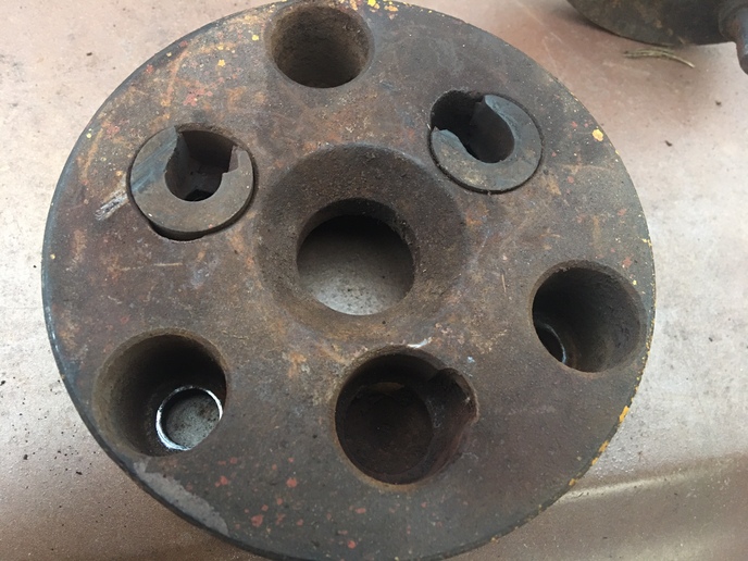
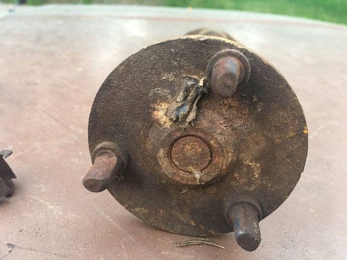
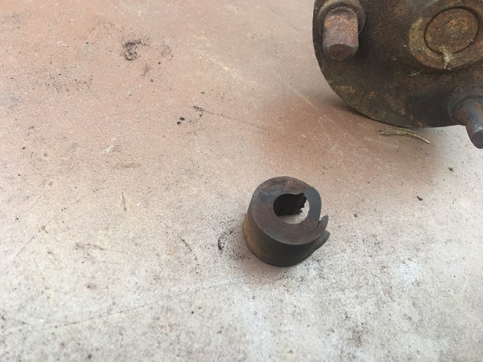
here is a few pics of the brackets, pump and drive hub. the drive hub is for a ford/sherman 54c2055 the pto is for a 8n 3/4x13" 194354. the parts that attach the pump to the shaft came off a junk loader from a ford 8n. In case your wondering, I used the ford drive hub because the one for the allis had 10 splines and the pto that matched it was only 10" long and wouldn"t be long enough to make it through the bollister. still have to clean up some welds and grind off any sharp corners.
Our front mounted pump, for a 200 industrial on a 17, has a chain gear on it and a gear on the end of the shaft. It is coupled with a double chain. Also the shaft is held in by bolts in the 2 bolt holes there on the front of the tractor. We had to get new pieces, i think from someone in Iowa, because ti was welded on the 14 that it was on. So, we didn"t have to build that support on the front. Sorry no pictures.
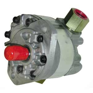
Hey DT,,here are some pics of the factory bracket,,not very good as the dang loader in the way,,but will give you an idea. The end bracket where the pump bolts to is 3/4" thick and the two cylindrical studs are 1 1/4" round stock. The bracket hold-down bolts go thru these two studs and bolt to the front of tractor. This wouldn"t be too awful hard to fabricate, if you had one to pattern to.
now that"s how it"s supposed to look........looks a heck of a lot better than the mess I made. at least I got the drive hub and pto installed, I can mess with the way the pump is attached after I get it back together. had to get another radiator, mine got a hole in it and when I was trying to fix it I just made it worse, it had been patched a bunch of times already. Made the trip to maryland and got one from paul. btw a huge thank you to paul for helping with the radiator situation.
Hey DT,,that is a Lovejoy style coupling. I don"t think it will work for you as the coupling on the pump end has to help support the shaft . The Lovejoy requires some sort of support for itself. The double row chain seen on these pics is what helps support the shaft end.
Hey DT,,that is a Lovejoy style coupling. I don"t think it will work for you as the coupling on the pump end has to help support the shaft . The Lovejoy requires some sort of support for itself. The double row chain seen on these pics is what helps support the shaft end.
yes that is what I used on my WD45 was a love joy but it isn"t carrying that much weight and it"s a tight fit to put a pump in between front pulley and the steering bolster but I wouldn"t be afraid to use one. If I remember I"ll take a picture of the bracket that goes on the front pump on my D-15 I would think it would be the same as a D-14 Kenny L.
it"s definitely a tight squeeze. thanks for the pictures, I"m thinking once I get the hydro lines figured out I"m probly gonna need to get some thicker steel for the pump mount. when it first fired it up after putting the pump on everything ran true, but there was a small vibration, after switching the bolts on the flex coupler it runs smooth and straight, thanks for the tip. dt
between the old ford loader and the loader I got with the d14 I had enough hoses/couplers to hook up the hydro"s. All my other loader valves you pulled back to raise the bucket, this one you pull it back to drop it. I switched the hoses to work the way I"m used to only to have to change them back for the float position to work!!!


 8613371530291