
what causes a hydraulic pump to get hot free sample

You can use multiple different upgrades and tuning methods on hydraulic systems. Many users will invest in upgrades that promise more flow and speed. The issue with these upgrades is that they"re not always fit for the hydraulic systems they"re applied to.
Since everything needs to stay in balance, you must make sure your upgrades match the entirety of your hydraulic system. For example, a higher flow pump can help give increased capabilities to a hydraulic system, but did you also check to see if the system"s hoses and piping can handle that increase in flow?
The increased flow can hit your smaller hoses hard and require more pressure just to get through them. This goes for any part of the hydraulic system that isn"t readily capable of handling more flow.
If a component becomes a flow throttle, the increase in pressure at the site can cause an overall pressure drop in the system. Also, the energy required to force flow will directly translate to an increase in heat, which lowers the systems efficiency and effectiveness.
When you make upgrades, also ascertain if you need to change other components. In the example of the higher flow pump, you can simply increase your hose size, and that makes all the difference.
Is your hydraulic pump getting excessively hot during normal operation? Pumps do generate heat when running, however they are designed with specific heat parameters in mind. Overheating is an abnormal condition that leads to destructive issues such as thinning of hydraulic fluid, which leads to reduced lubrication, metal-on-metal contact of moving parts. And accelerated pump wear and failure.
Therefore it is never a good idea to ignore a pump that is exceeding its heat parameters under normal load. There are a number of factors that contribute to an excess buildup of heat and in this article, we’ll explain some of these issues.
Hydraulic fluid viscosity refers to the thickness or “resistance to pouring” of your hydraulic fluid. This is very important to the correct operation of your pump. The fluid not only transmits the power that moves your drives and actuators. It also lubricates internal components and removes heat from the system. Hydraulic fluid is designed to operate at a specific temperature range. As it heats, it becomes thinner and eventually it will lose the ability to lubricate moving parts. The increased friction may cause the pump to heat up, and naturally increased wear will be taking place when this is happening. On the other hand, hydraulic fluid that is too thick flows less efficiently within the system, which also results in heat buildup.
Fluid that is contaminated with dirt, debris, water and other impurities may cause heat build up in a few ways. Blocked fluid filters, pipes and strainers place undue load on the pump or even lead to pressure drops on the back side of filters that cause cavitation.
Low fluid levels can result in a condition in which not enough flow is reaching the critical hydraulic components and moving parts. This is known as oil starvation and just like running your car without oil, it will increase metal-on-metal friction and lead to increased heat and wear. Oil starvation can also be caused by clogged hydraulic filters, incorrect fluid reservoir design.
Cavitation is the rapid formation and implosion of air cavities in the hydraulic fluid. When these air cavities collapse under pressure, they generate a lot of heat. In fact, temperatures can reach up to 2700 degrees C at the point of implosion! Not only does cavitation compromise the lubrication properties of the oil, the excessive heat that is generated is extremely damaging to the hydraulic pump and the system as a whole. Attacking hoses and seals and causing metal components to expand and wear.
This happens when air makes its way into the system via air leaks at points like pump seals, and pipe fittings. And what happens next in a hydraulic system? Compression! Air generates heat when compressed, which naturally leads to an increase in temperature if left untreated. In extreme circumstances it can also lead to ‘hydraulic dieseling’ whereby compressed air bubbles actually explode in the same process that powers diesel engines. This is not good and leads to degradation of the fluid and damage to system components through loss of lubrication and burning of seals.
As pumps wear, the internal leakage or “slippage” increases. Essentially, fluid is able to make its way past tight fitting components, which reduces the efficiency of the pump, but in addition, as this occurs, fluid moves from a high pressure to a low pressure without doing any mechanical work, since according to the laws of physics energy cannot be destroyed, it is instead converted into heat.
A build-up of excessive heat is a symptom of hydraulic pump problems, but it is far from the only signal that there may be something wrong. There are other important warning signs that you should pay attention to. These include unusual noises, pressure problems and flow problems. Each of these symptoms provide clues about any potential pump problems that need to be addressed - so it’s important to familiarise yourself with all of these issues. To help, we’ve created a downloadable troubleshooting guide containing more information about each of these issues. So that you can keep your system up and running and avoid unplanned downtime. Download ithere.

When hydraulic oil is getting overheated, there could be several common causes that also cause the system to overheat. First, it is crucial to understand the type of hydraulic system you are using to begin troubleshooting why the system is overheating.
The first cause of hydraulic oil overheating is when the hydraulic equipment system parts and components are nearing the end of their useful lifespans. As they degrade, due to increased internal leakage, they have to work harder to maintain the desired system pressure.
For example, your hydraulic pump is wearing out and needs to be replaced. Due to internal wear pressurised fluid escapes from the high pressure side to the low pressure side generating heat increasing the temperature of the hydraulic fluid and causing circuit overheating.
It is understood that you may want to make system upgrades or changes to customize the system to reflect your specific needs. However, when you do not consider the entire system, it can cause the system to work hard, give off more heat, and increase hydraulic oil temperatures, leading to circuit overheating.
For instance, you may want to increase the fluid flow rate through the system. However, you did not account for the size of hoses and tubing to accommodate the higher flow rates. As a result, the system has to work hard to force the increased flow rates through incompatible hoses and tubes, resulting in more heat generation and fluid overheating.
Tweaking your hydraulic system is perfectly acceptable to optimize its performance. However, where many people go wrong is they only adjust one part of the system and fail to think about how the adjustment will impact other parts of the system.
For example, suppose you make an adjustment to the pump compensator and increase the pressure yet fail to also make a similar adjustment to the relief valve. In this instance the relief valve will blow off more frequently generating more heat and therefore increasing the circuit fluid temperature.
Every component in a hydraulic system imposes a load on the pump, this is referred to as the pressure drop across the particular component. The figure will vary depending upon the flow rate and the energy lost from the fluid due to the pressure drop is converted into heat. If the overall pressure drop across all the components in the circuit unexpectedly increases so the heat generated across the circuit will also increase.
If the fluid is not cooled to compensate for this the fluid temperature continues to increase as the other parts and components generate excessive heat.
If there is dirt, sludge, debris, or water in the hydraulic fluid, the system will generate more heat as it attempts to compensate for the contaminants and push the fluid through the system. Therefore, it is always vital to check your fluid for contamination and change it and or improve fluid filtration when required.
After troubleshooting overheating problems, if you have determined it is not due to the four common causes mentioned above, then there are two general ways you can resolve fluid overheating problems. You can either increase the reservoir capacity to dissipate heat or decrease the amount of heat being generated by the system.
Another way to increase the heat dissipation is to inspect the current heat exchangers, if they are being used, and make the appropriate adjustments. In some cases, you may want to install additional heat exchangers to help reduce the fluid temperature.
In addition, check the airflow around the reservoir as the higher the airflow the more efficiently the reservoir radiates the heat from the fluid held inside it.
To find hydraulic parts, components, and accessories to help you resolve hydraulic oil overheating problems, or if you require assistance in troubleshooting system overheating, please feel free to contact White House Products, Ltd. at +44 (0) 1475 742500 today!

Hydraulic pumps generate heat while they run. However, hydraulic fluid temperature should never exceed180 degreesF (82 degrees C) under normal working conditions. If your hydraulic pump temperature rises above this, then that is a sign that your pump is likely overheating. One of the most common causes of hydraulic system failure is a hydraulic pump that runs too hot or overheats.
When a hydraulic pump runs at a too-high temperature for too long, it can ultimately lead to pump failure. Once a hydraulic pump begins to fail, it can potentially damage the entire hydraulic system by sending contaminants and debris into the system that can damage its other components.
In addition, when some hydraulic fluids are subject to high temperatures, they can thin and lose their viscosity. When hydraulic fluid is too thin, it is much more likely to leak, and fluid that has lost its viscosity cannot lubricate your pump properly. Extremely hot fluid can also damage pump seals, further increasing the chance of a pump leak.
Some hydraulic fluids thicken and oxidize when exposed to high heat instead of thinning. When hydraulic fluids are too thick, they can restrict flow throughout the entire hydraulic system, which leads to your system heating up even further.
The sooner you determine why your hydraulic pump is running hot and repair the cause of the problem, the less likely your hydraulic system will develop irreversible damage or fail completely.
Hydraulic pumps overheat for many reasons. Just a few of the most common causes of hydraulic pump overheating include: Contaminated hydraulic fluid. When fluid has debris and dirt, contaminant particles can quickly build up on hydraulic system filters, leading to filter clogs. Your pump has to work harder to pump fluid through clogged filters, which leads to overheating.
Aeration. Air leaks at seals and fittings on your hydraulic system components can lead to air entering your system and forming bubbles in your fluid. Air bubbles generate heat when your system compresses them and then pass this heat into the surrounding fluid, overheating it.
Low reservoir fluid. Since your hydraulic system releases some of the heat it creates into reservoir fluid, a low reservoir fluid level can contribute to overheating.
Blocked or damaged heat exchanger. This component is also an important part of your hydraulic pump"s cooling system. If it is blocked or damaged, then it cannot help remove heat from your pump properly.
Once your hydraulic pump beings overheating, you need to find the cause of the problem and repair it. That way, your pump can begin operating within its ideal temperature range again.
If your pump overheats due to fluid contamination, then either remove all contaminants from existing fluid or remove the current contaminated fluid from the system and add fresh fluid. Be sure to filter all fresh hydraulic fluid before you add it to your system because even this fresh fluid can contain contaminants. Also, replace your fluid filters on a regular basis to prevent the overheating that can occur when these filters become blocked with debris.
If air has entered your system through leaky seals and fittings, then have a hydraulic system repair expert inspect and replace or tighten these fittings. Have a hydraulic system repair expert also look at heat exchanger damage to determine if the exchanger needs repairing or replacing.
Finally, be sure to check your system"s reservoir fluid level on a regular basis. Add new fluid when necessary to help this reservoir perform its important task of helping to keep your pump cool.
Your hydraulic pump should always operate within its ideal temperature range. If your pump is running hot, then contact the hydraulic pump experts at Quad Fluid Dynamics, Inc., forhydraulic pump diagnosis and repairtoday.

When a hydraulic system fails, finding the source of the problem can be a challenge. Though hydraulic systems primarily consist of a sump, motor, pump, valves, actuators and hydraulic fluid, any of these parts could be the source of failure. That"s not to mention the additional potential for failure through human error and faulty maintenance practices. If your system fails, you need to know why it fails, how to find the failure and how to keep it running smoothly in the future, all while keeping personnel safe.
It"s often easy to tell when a hydraulic system fails — symptoms can include high temperatures, low pressure readings and slow or erratic operation are glaring problems. But what are the most common causes of hydraulic systems failures? We can trace most hydraulic issues back to a few common causes, listed below.
Air and water contamination are the leading causes of hydraulic failure, accounting for 80 to 90% of hydraulic failures. Faulty pumps, system breaches or temperature issues often cause both types of contamination.
Air contamination is the entrance of air into a hydraulic system and consists of two types — aeration and cavitation. Both can cause severe damage to the hydraulic system over time by wearing down the pump and surrounding components, contaminating hydraulic fluids and even overheating the system. Although we are not pump manufacturers, we know it is essential to be aware of these types of contamination and how to identify their symptoms.
Cavitation:Hydraulic oil consists of about 9% dissolved air, which the pump can pull out and implode, causing pump problems and damage to the pump and to other components in a hydraulic system over time. You can identify this problem if your hydraulic pump is making a whining noise.
Aeration:Aeration occurs when air enters the pump cavity from an outside source. Usually, loose connections or leaks in the system cause this issue. Aeration also creates a sound when the pump is running, which sounds like knocking.
Water contamination is also a common problem in hydraulic systems, often caused by system leaks or condensation due to temperature changes. Water can degrade hydraulic components over time through oxidation and freeze damage. A milky appearance in hydraulic fluid can help you identify water contamination.
Fluid oxidization: Extreme heat can cause hydraulic fluid to oxidize and thicken. This fluid thickening can cause buildups in the system that restrict flow, but can also further reduce the ability of the system to dissipate heat.
Fluid thickening:Low temperatures increase the viscosity of hydraulic oil, making it harder for the oil to reach the pump. Putting systems under load before the oil reaches 70 degrees or more can damage the system through cavitation.
Fluid levels and quality can affect hydraulic system performance. Low fluid levels and inappropriate filtration can result in air contamination, while fluid contamination can cause temperature problems. Leaks can further exacerbate both issues.
Using the correct type of fluid is also essential, as certain hydraulic oils are compatible with specific applications. There are even oil options that offer higher resistance to temperature-related problems. Some oils even offer anti-wear and anti-foam additives to help prevent against wear and air contamination, respectively.
Human error is the base cause of many hydraulic system problems. Some of the most common errors that may result in your hydraulic pump not building pressure include the following.
Faulty installations: Improper installation of any component in a hydraulic system can result in severe errors. For example, the pump shaft may be rotating in the wrong direction, negatively affecting pressure buildup, or pipes may be incorrectly fitted, resulting in leaks.
Incompatible parts: An inexperienced installer may put mismatched components together, resulting in functional failures. For example, a pump may have a motor that runs beyond its maximum drive speed.
Improper maintenance or usage:Using systems outside their operational capabilities or failing to perform regular maintenance are some of the most common causes of hydraulic system damage, but are easy to rectify through updated maintenance policies and training.
The sources of system failures can be tricky to identify, but some hydraulic troubleshooting steps can help narrow down the options. So how do you troubleshoot a hydraulic system? Here are some of the fundamentals.
Check the pump: Take the pump assembly apart and assess all parts to ensure that they are functional and installed correctly. The most common problem areas include the pump shaft, coupling and filter.
Check the fluids:Check the level, color and viscosity of the hydraulic oil to ensure it meets specifications and has not become contaminated. Low hydraulic fluid symptoms include pressure or power loss. When in doubt, drain and replace the fluids.
Check the seals: Look for evidence of any fluid leakage around your hydraulic system"s seals, especially the shaft seal. Leakage can indicate worn-out or blown seals that can cause malfunctions with pumps, motors and control valves.
Check the filters: Ensure filters are clear of plugs and blockages. Common clogged hydraulic filter symptoms include sluggish operation and noisy operation.
Check valves and lines: Observe all lines for potential leaks, and tighten every connection point. Also, check the relief valve for any signs of damage.
Run the system: When you have completed all these essential checks, turn on the system and monitor it for pressure and temperature fluctuations, as well as abnormal sounds. If all seems well, check your pressure sensor for potential failure.
Hydraulic system issues are inevitable at some point. However, simple steps can help you avoid these issues and increase the longevity of your hydraulic system. On top of effective troubleshooting, you can prevent hydraulic system failure by taking the following steps.
Follow specifications: We can trace the most common hydraulic system issues back to fundamental system problems like incompatible or improperly installed parts. For this reason, it"s essential to always double-check specifications to ensure your purchased parts can work together seamlessly.
Consult with professionals: When purchasing new equipment, consult with industry peers and professionals to discover what they recommend. While manufacturers can tell you how a product should work, industry professionals can provide concrete examples of how well the equipment works for their industry.
Perform maintenance: It is essential to focus your operations on equipment longevity. Review your daily, monthly and annual maintenance procedures to ensure you are covering every aspect of your system according to best maintenance practices and catch symptoms early on.
On top of these steps, look into hydraulic system products that are specifically designed to help prevent failures. One such product is Bear-Loc® by York Precision. This innovative locking actuator is a safe, reliable feature for hydraulic components, automatically locking when sleeve pressure is relieved, preventing movement if a hydraulic system fails. This way, your can protect your personnel from injuries related to hydraulic failures. Even better, York Precision offers in-house design, engineering expertise and machining and manufacturing capabilities to produce a hydraulic locking device that meets your exact specifications.
Regularly review hydraulic system maintenance, always following manufacturer recommendations and industry best practices. Also, consider the storage condition, external influences, working pressure and usage frequency of your system to tailor your maintenance schedule and procedures.
Daily tasks:Take care of a few simple daily checks to avoid issues. For example, personnel should check the oil levels, hoses and connections and listen to the pump for abnormal sounds.
Routine tasks:Plan and execute a weekly and monthly maintenance routine, checking for the most common failure sources given your system"s working conditions. These should include components, filters and the condition of the oil.
Complete system checks: Depending on the conditions of your system, you and your team should perform complete systems checks monthly, quarterly or annually. Tasks should include running a comprehensive report on the system, cleaning devices, draining the system and replacing damaged parts.
When completing system maintenance, it is essential to follow basic safety procedures. Faulty or broken parts can cause leaks, bursts and projectiles that can severely injure personnel. Some common injuries include bruises, cuts and abrasions. However, pinhole leaks can inject oil into the body, causing septicemia that can result in the loss of a limb if not addressed immediately. To avoid these injuries, be sure to follow basic safety guidelines.
Wear safety equipment:Always wear appropriate safety gear when working close to a system, including a helmet, glasses, gloves and protective clothing and shoes.
Be mindful of location:Do not stand at endpoints while working on hydraulic systems. This safety measure can help prevent loss of limb and life, as there is a lot of pressure built up in these areas that can release and result in life-threatening situations.
Use caution around running systems:Always keep an eye out on pressure taps, couplings and hoses when they are under pressure. If something does not look right, power down the system before checking it. Loose or faulty parts can easily become deadly projectiles.
The best safety measures, however, are to perform excellent maintenance and use high-quality parts. If you"re looking for a quality hydraulic component manufacturer, York Precision Machining & Hydraulics can help.

www.powermotiontech.com is using a security service for protection against online attacks. An action has triggered the service and blocked your request.
Please try again in a few minutes. If the issue persist, please contact the site owner for further assistance. Reference ID IP Address Date and Time 8bf2006c85a66667641f5dd58dcb3d35 63.210.148.230 03/07/2023 09:07 AM UTC

Check that the electric motor is running. Although this is a simple concept, before you begin replacing parts, it’s critical that you make sure the electric motor is running. This can often be one of the easiest aspects to overlook, but it is necessary to confirm before moving forward.
Check that the pump shaft is rotating. Even though coupling guards and C-face mounts can make this difficult to confirm, it is important to establish if your pump shaft is rotating. If it isn’t, this could be an indication of a more severe issue, and this should be investigated immediately.
Check the oil level. This one tends to be the more obvious check, as it is often one of the only factors inspected before the pump is changed. The oil level should be three inches above the pump suction. Otherwise, a vortex can form in the reservoir, allowing air into the pump.
If the oil level is low, determine where the leak is in the system. Although this can be a difficult process, it is necessary to ensure your machines are performing properly. Leaks can be difficult to find.
What does the pump sound like when it is operating normally? Vane pumps generally are quieter than piston and gear pumps. If the pump has a high-pitched whining sound, it most likely is cavitating. If it has a knocking sound, like marbles rattling around, then aeration is the likely cause.
Cavitation is the formation and collapse of air cavities in the liquid. When the pump cannot get the total volume of oil it needs, cavitation occurs. Hydraulic oil contains approximately nine percent dissolved air. When the pump does not receive adequate oil volume at its suction port, high vacuum pressure occurs.
This dissolved air is pulled out of the oil on the suction side and then collapses or implodes on the pressure side. The implosions produce a very steady, high-pitched sound. As the air bubbles collapse, the inside of the pump is damaged.
While cavitation is a devastating development, with proper preventative maintenance practices and a quality monitoring system, early detection and deterrence remain attainable goals. UE System’s UltraTrak 850S CD pump cavitation sensor is a Smart Analog Sensor designed and optimized to detect cavitation on pumps earlier by measuring the ultrasound produced as cavitation starts to develop early-onset bubbles in the pump. By continuously monitoring the impact caused by cavitation, the system provides a simple, single value to trend and alert when cavitation is occurring.
The oil viscosity is too high. Low oil temperature increases the oil viscosity, making it harder for the oil to reach the pump. Most hydraulic systems should not be started with the oil any colder than 40°F and should not be put under load until the oil is at least 70°F.
Many reservoirs do not have heaters, particularly in the South. Even when heaters are available, they are often disconnected. While the damage may not be immediate, if a pump is continually started up when the oil is too cold, the pump will fail prematurely.
The suction filter or strainer is contaminated. A strainer is typically 74 or 149 microns in size and is used to keep “large” particles out of the pump. The strainer may be located inside or outside the reservoir. Strainers located inside the reservoir are out of sight and out of mind. Many times, maintenance personnel are not even aware that there is a strainer in the reservoir.
The suction strainer should be removed from the line or reservoir and cleaned a minimum of once a year. Years ago, a plant sought out help to troubleshoot a system that had already had five pumps changed within a single week. Upon closer inspection, it was discovered that the breather cap was missing, allowing dirty air to flow directly into the reservoir.
A check of the hydraulic schematic showed a strainer in the suction line inside the tank. When the strainer was removed, a shop rag was found wrapped around the screen mesh. Apparently, someone had used the rag to plug the breather cap opening, and it had then fallen into the tank. Contamination can come from a variety of different sources, so it pays to be vigilant and responsible with our practices and reliability measures.
The electric motor is driving the hydraulic pump at a speed that is higher than the pump’s rating. All pumps have a recommended maximum drive speed. If the speed is too high, a higher volume of oil will be needed at the suction port.
Due to the size of the suction port, adequate oil cannot fill the suction cavity in the pump, resulting in cavitation. Although this rarely happens, some pumps are rated at a maximum drive speed of 1,200 revolutions per minute (RPM), while others have a maximum speed of 3,600 RPM. The drive speed should be checked any time a pump is replaced with a different brand or model.
Every one of these devastating causes of cavitation threatens to cause major, irreversible damage to your equipment. Therefore, it’s not only critical to have proper, proactive practices in place, but also a monitoring system that can continuously protect your valuable assets, such as UE System’s UltraTrak 850S CD pump cavitation senor. These sensors regularly monitor the health of your pumps and alert you immediately if cavitation symptoms are present, allowing you to take corrective action before it’s too late.
Aeration is sometimes known as pseudo cavitation because air is entering the pump suction cavity. However, the causes of aeration are entirely different than that of cavitation. While cavitation pulls air out of the oil, aeration is the result of outside air entering the pump’s suction line.
Several factors can cause aeration, including an air leak in the suction line. This could be in the form of a loose connection, a cracked line, or an improper fitting seal. One method of finding the leak is to squirt oil around the suction line fittings. The fluid will be momentarily drawn into the suction line, and the knocking sound inside the pump will stop for a short period of time once the airflow path is found.
A bad shaft seal can also cause aeration if the system is supplied by one or more fixed displacement pumps. Oil that bypasses inside a fixed displacement pump is ported back to the suction port. If the shaft seal is worn or damaged, air can flow through the seal and into the pump’s suction cavity.
As mentioned previously, if the oil level is too low, oil can enter the suction line and flow into the pump. Therefore, always check the oil level with all cylinders in the retracted position.
If a new pump is installed and pressure will not build, the shaft may be rotating in the wrong direction. Some gear pumps can be rotated in either direction, but most have an arrow on the housing indicating the direction of rotation, as depicted in Figure 2.
Pump rotation should always be viewed from the shaft end. If the pump is rotated in the wrong direction, adequate fluid will not fill the suction port due to the pump’s internal design.
A fixed displacement pump delivers a constant volume of oil for a given shaft speed. A relief valve must be included downstream of the pump to limit the maximum pressure in the system.
After the visual and sound checks are made, the next step is to determine whether you have a volume or pressure problem. If the pressure will not build to the desired level, isolate the pump and relief valve from the system. This can be done by closing a valve, plugging the line downstream, or blocking the relief valve. If the pressure builds when this is done, there is a component downstream of the isolation point that is bypassing. If the pressure does not build up, the pump or relief valve is bad.
If the system is operating at a slower speed, a volume problem exists. Pumps wear over time, which results in less oil being delivered. While a flow meter can be installed in the pump’s outlet line, this is not always practical, as the proper fittings and adapters may not be available. To determine if the pump is badly worn and bypassing, first check the current to the electric motor. If possible, this test should be made when the pump is new to establish a reference. Electric motor horsepower is relative to the hydraulic horsepower required by the system.
For example, if a 50-GPM pump is used and the maximum pressure is 1,500 psi, a 50-hp motor will be required. If the pump is delivering less oil than when it was new, the current to drive the pump will drop. A 230-volt, 50-hp motor has an average full load rating of 130 amps. If the amperage is considerably lower, the pump is most likely bypassing and should be changed.
Figure 4.To isolate a fixed displacement pump and relief valve from the system, close a valve or plug the line downstream (left). If pressure builds, a component downstream of the isolation point is bypassing (right).
The most common type of variable displacement pump is the pressure-compensating design. The compensator setting limits the maximum pressure at the pump’s outlet port. The pump should be isolated as described for the fixed displacement pump.
If pressure does not build up, the relief valve or pump compensator may be bad. Prior to checking either component, perform the necessary lockout procedures and verify that the pressure at the outlet port is zero psi. The relief valve and compensator can then be taken apart and checked for contamination, wear, and broken springs.
Check the tank line temperature of the relief valve with a temperature gun or infrared camera. The tank line should be near ambient temperature. If the line is hot, the relief valve is either stuck partially open or is set too low.
Install a flow meter in the case drain line and check the flow rate. Most variable displacement pumps bypass one to three percent of the maximum pump volume through the case drain line. If the flow rate reaches 10 percent, the pump should be changed. Permanently installing a flow meter in the case drain line is an excellent reliability and troubleshooting tool.
Ensure the compensator is 200 psi above the maximum load pressure. If set too low, the compensator spool will shift and start reducing the pump volume when the system is calling for maximum volume.
Performing these recommended tests should help you make good decisions about the condition of your pumps or the cause of pump failures. If you change a pump, have a reason for changing it. Don’t just do it because you have a spare one in stock.
Conduct a reliability assessment on each of your hydraulic systems so when an issue occurs, you will have current pressure and temperature readings to consult.
Al Smiley is the president of GPM Hydraulic Consulting Inc., located in Monroe, Georgia. Since 1994, GPM has provided hydraulic training, consulting and reliability assessments to companies in t...

Overheating ranks No. 2 in the list of most common problems with hydraulic equipment. Unlike leaks, which rank No. 1, the causes of overheating and its remedies are often not well understood by maintenance personnel
Heating of hydraulic fluid in operation is caused by inefficiencies. Inefficiencies result in losses of input power, which are converted to heat. A hydraulic system’s heat load is equal to the total power lost (PL) through inefficiencies and can be expressed as:
If the total input power lost to heat is greater than the heat dissipated, the hydraulic system will eventually overheat. Installed cooling capacity typically ranges between 25 and 40 percent of input power, depending on the type of hydraulic system.
How hot is too hot? Hydraulic fluid temperatures above 180°F (82°C) damage most seal compounds and accelerate degradation of the oil. While the operation of any hydraulic system at temperatures above 180°F should be avoided, fluid temperature is too high when viscosity falls below the optimum value for the hydraulic system’s components. This can occur well below 180°F, depending on the fluid’s viscosity grade.
To achieve stable fluid temperature, a hydraulic system’s capacity to dissipate heat must exceed its heat load. For example, a system with continuous input power of 100 kW and an efficiency of 80 percent needs to be capable of dissipating a heat load of at least 20 kW. Assuming this system has a designed cooling capacity of 25 kW, anything that increases heat load above 25 kW or reduces the cooling system’s capacity below 25 kW will cause the system to overheat.
Consider this example. I was recently asked to investigate and solve an overheating problem in a mobile application. The hydraulic system was comprised of a diesel-hydraulic power unit, which was being used to power a pipe-cutting saw. The saw was designed for sub-sea use and was connected to the hydraulic power unit on the surface via a 710-foot umbilical. The operating requirements for the saw were 24 GPM at 3,000 PSI.
The hydraulic power unit had a continuous power rating of 37 kW and was fitted with an air-blast heat exchanger. The exchanger was capable of dissipating 10 kW of heat under ambient conditions or 27 percent of available input power (10/37 x 100 = 27). The performance of all cooling circuit components were checked and found to be operating within design limits.
At this point it, was clear that the overheating problem was being caused by excessive heat load. Concerned about the length of the umbilical, I calculated its pressure drop. The theoretical pressure drop across 710 feet of ¾-inch pressure hose at 24 GPM is 800 PSI. The pressure drop across the same length of 1-inch return hose is 200 PSI. The theoretical heat load produced by the pressure drop across the umbilical of 1,000 PSI (800 + 200 = 1,000) was 10.35 kW. This meant that the heat load of the umbilical was 0.35 kW more than the heat dissipation capacity of the hydraulic system’s heat exchanger. This, when combined with the system’s normal heat load (inefficiencies) was causing the hydraulic system to overheat.
Hydraulic systems dissipate heat through the reservoir. Therefore, check the reservoir fluid level and if low, fill to the correct level. Check that there are no obstructions to airflow around the reservoir, such as a buildup of dirt or debris.
Inspect the heat exchanger and ensure that the core is not blocked. The ability of the heat exchanger to dissipate heat is dependent on the flow-rate and temperature of both the hydraulic fluid and the cooling air or water circulating through the exchanger. Check the performance of all cooling circuit components and replace as necessary.
An infrared thermometer can be used to check the performance of a heat exchanger, provided the design flow-rate of hydraulic fluid through the exchanger is known. To do this, measure the temperature of the oil entering and exiting the exchanger and substitute the values in the following formula:
For example, if the measured temperature drop across the exchanger is 4ºC and the design oil flow-rate is 90 L/min, the exchanger is dissipating 10 kW of heat. Relating this to a system with a continuous input power of 100 kW, the exchanger is dissipating 10 percent of input power. If the system is overheating, it means that either there is a problem in the cooling circuit or the capacity of the exchanger is insufficient for the ambient operating conditions.
On the other hand, if the measured temperature drop across the exchanger is 10ºC and the design oil flow-rate is 90 L/min, the exchanger is dissipating 26 kW of heat. Relating this to a system with a continuous input power of 100 kW, the exchanger is dissipating 26 percent of input power. If the system is overheating, this means that the efficiency of the system has fallen below 74 percent.
Where there is a pressure drop, heat is generated. This means that any component in the system that has abnormal, internal leakage will increase the heat load on the system and can cause the system to overheat. This could be anything from a cylinder that is leaking high-pressure fluid past its piston seal, to an incorrectly adjusted relief valve. Identify and change-out any heat-generating components.
A common cause of heat generation in closed center circuits is the setting of relief valves below, or too close to, the pressure setting of the variable-displacement pump’s pressure compensator. This prevents system pressure from reaching the setting of the pressure compensator. Instead of pump displacement reducing to zero, the pump continues to produce flow, which passes over the relief valve, generating heat. To prevent this problem in closed center circuits, the pressure setting of the relief valve(s) should be 250 PSI above the pressure setting of the pump’s pressure compensator (Figure 1).
Continuing to operate a hydraulic system when the fluid is over-temperature is similar to operating an internal combustion engine with high coolant temperature. Damage is guaranteed. Therefore, whenever a hydraulic system starts to overheat, shut it down, identify the cause and fix it.
Brendan Casey has more than 20 years experience in the maintenance, repair and overhaul of mobile and industrial equipment. For more information on reducing the operating cost and increasing the...

The second leading cause of hydraulic pump failure, behind contamination, is cavitation. Cavitation is a condition that can also potentially damage or compromise your hydraulic system. For this reason, understanding cavitation, its symptoms, and methods of prevention are critical to the efficiency and overall health of not just your hydraulic pump, but your hydraulic system as a whole.
The product of excessive vacuum conditions created at the hydraulic pump’s inlet (supply side), cavitation is the formation, and collapse of vapors within a hydraulic pump. High vacuum creates vapor bubbles within the oil, which are carried to the discharge (pressure) side. These bubbles then collapse, thus cavitation.
This type of hydraulic pump failure is caused by poor plumbing, flow restrictions, or high oil viscosity; however, the leading cause of cavitation is poor plumbing. Poor plumbing is the result of incorrectly sized hose or fittings and or an indirect (not straight or vertical) path from the pump to the reservoir. Flow restrictions, for example, include buildup in the strainer or the use of an incorrect length of hose or a valve that is not fully open. Lastly, high oil viscosity—or oil that is too viscous—will not flow easily to the pump. Oil viscosity must be appropriate for the climate and application in which the hydraulic pump is being used.
The greatest damage caused by cavitation results from the excessive heat generated as the vapor bubbles collapse under the pressure at the pump outlet or discharge side. On the discharge side, these vapor bubbles collapse as the pressure causes the gases to return to a liquid state. The collapses of these bubbles result in violent implosions, drawing surrounding material, or debris, into the collapse. The temperature at the point of implosion can exceed 5,000° F. Keep in mind that in order for these implosions to happen, there must be high vacuum at the inlet and high pressure at the outlet.
Without a pressure condition at the outlet, or discharge side, these vapors merely form voids in the oil that reduce lubrication effectiveness. This results in friction and wear, which while seemingly mild compared to the excessive heat and violent implosions, can become detrimental over time.
Cavitation is usually recognized by sound. The pump will either produce a “whining” sound (more mild conditions) or a “rattling” sound (from intense implosions) that can sound like marbles in a can. If you’re hearing either of these sounds, you first need to determine the source. Just because you hear one of these two sounds doesn’t guarantee that your hydraulic pump is the culprit.
To isolate the pump from the power take-off (PTO) to confirm the source, remove the bolts that connect the two components and detach the pump from the PTO. Next, run the PTO with no pump and see if the sound is still present. If not, it is safe to assume your hydraulic pump is the problem.
Another sign you may be experiencing cavitation is physical evidence. As part of your general maintenance, you should be inspecting and replacing the hydraulic oil filter"s elements at regular intervals based on the duty cycle of the application and how often it is used. If at any time during the inspection and replacement of these elements you find metallic debris, it could be a sign that you’re experiencing cavitation in the pump.
The easiest way to determine the health of your complete hydraulic circuit is to check the filter. Every system should have a hydraulic oil filter somewhere in-line. Return line filters should be plumbed in the, you guessed it, return line from the actuator back to tank—as close to the tank as possible. As mentioned earlier, this filter will have elements that should be replaced at regular intervals. If you find metallic debris, your pump could be experiencing cavitation. You’ll then need to flush the entire system and remove the pump for inspection.
Conversely, if you’ve already determined the pump to be damaged, you should remove the filter element, cut it open, and inspect it. If you find a lot of metal, you’ll need to flush the entire system and keep an eye on the other components that may be compromised as a result.
Once cavitation has been detected within the hydraulic pump, you’ll need to determine the exact cause of cavitation. If you don’t, cavitation can result in pump failure and compromise additional components—potentially costing you your system.
Since the pump is fed via gravity and atmospheric pressure, the path between the reservoir and the pump should be as vertical and straight as possible. This means that the pump should be located as close to the reservoir as is practical with no 90-degree fittings or unnecessary bends in the supply hose. Whenever possible, be sure to locate the reservoir above the pump and have the largest supply ports in the reservoir as well. And don"t forget, ensure the reservoir has a proper breather cap or is pressurized (3–5 PSI), either with an air system or pressure breather cap.
Be sure the supply line shut-off valve (if equipped) is fully open with no restrictions. This should be a “full-flow” ball valve with the same inside diameter (i.d.) as the supply hose. If feasible, locate a vacuum gauge that can be T’d into the supply line and plumb it at the pump inlet port. Activate the PTO and operate a hydraulic function while monitoring the gauge. If it reads >5 in. Hg, shut it off, and resume your inspection.
If a strainer is present in the reservoir, inspect it, and remove any gunk or buildup that may be restricting supply flow. Next, check the inlet (suction) hose for any visible layline (descriptive markings on the hose). The industry standard “suction” hose nomenclature will read 100R4, or possibly SAER4. This will indicate the hose has an inner bladder that’s been vulcanized to a heavy spiral wire.
A hose with an inner bladder vulcanized to a heavy spiral is designed to withstand vacuum conditions as opposed to outward pressure. The layline will also denote the size of the hose (i.d.). You can use Muncie Power’s PPC-1 hydraulic hose calculator to determine the optimal diameter for your particular application based on operating flows.
Another consideration, in regards to the inlet plumbing, is laminar flow. To reduce noise and turbulence at the pump inlet, the length of the supply hose should be at least 10 times its diameter. This means that any type of shut-off valve or strainer at the reservoir should be at least 10 diameters from the pump inlet. A flared, flange-style fitting at the pump inlet can also reduce pump noise by at least 50 percent compared to a SAE, JIC, or NPT fitting.
Selecting the proper viscosity of hydraulic fluid for your climate and application is also critical. Oil that is too viscous will not flow as easily to the pump. Consult your local hydraulic oil supplier for help selecting the optimal fluid viscosity.
By maintaining a regular maintenance schedule, remaining vigilant for any signs or symptoms, and taking preventative measures, the good news is that you should be able to prevent cavitation and experience efficient operation for the duration of your pump’s lifespan.
Poor plumbing is the leading cause of cavitation and can be prevented by selecting a properly sized hose, choosing the appropriate fittings, ensuring the most direct, straight routing from the pump to the reservoir, etc.
Since joining the company in 2007, Ben Gillum has served in various capacities including shipping and receiving clerk, CS assembly, customer service manager, product application specialist, training and education assistant manager, and warranty and returns manager.

?I get e-mails like this all the time. I never find time to read them. I decided to read Issue #30 and I couldn"t put it down. I"ll make time from now on.?
?I just love this newsletter. As a Hydraulics Instructor for Eaton, I make copies and distribute them to my students as I address various topics. Please keep "em coming.?
Hydraulic pumps are mechanisms in hydraulic systems that move hydraulic fluid from point to point initiating the production of hydraulic power. Hydraulic pumps are sometimes incorrectly referred to as “hydrolic” pumps.
They are an important device overall in the hydraulics field, a special kind of power transmission which controls the energy which moving fluids transmit while under pressure and change into mechanical energy. Other kinds of pumps utilized to transmit hydraulic fluids could also be referred to as hydraulic pumps. There is a wide range of contexts in which hydraulic systems are applied, hence they are very important in many commercial, industrial, and consumer utilities.
“Power transmission” alludes to the complete procedure of technologically changing energy into a beneficial form for practical applications. Mechanical power, electrical power, and fluid power are the three major branches that make up the power transmission field. Fluid power covers the usage of moving gas and moving fluids for the transmission of power. Hydraulics are then considered as a sub category of fluid power that focuses on fluid use in opposition to gas use. The other fluid power field is known as pneumatics and it’s focused on the storage and release of energy with compressed gas.
"Pascal"s Law" applies to confined liquids. Thus, in order for liquids to act hydraulically, they must be contained within a system. A hydraulic power pack or hydraulic power unit is a confined mechanical system that utilizes liquid hydraulically. Despite the fact that specific operating systems vary, all hydraulic power units share the same basic components. A reservoir, valves, a piping/tubing system, a pump, and actuators are examples of these components. Similarly, despite their versatility and adaptability, these mechanisms work together in related operating processes at the heart of all hydraulic power packs.
The hydraulic reservoir"s function is to hold a volume of liquid, transfer heat from the system, permit solid pollutants to settle, and aid in releasing moisture and air from the liquid.
Mechanical energy is changed to hydraulic energy by the hydraulic pump. This is accomplished through the movement of liquid, which serves as the transmission medium. All hydraulic pumps operate on the same basic principle of dispensing fluid volume against a resistive load or pressure.
Hydraulic valves are utilized to start, stop, and direct liquid flow in a system. Hydraulic valves are made of spools or poppets and can be actuated hydraulically, pneumatically, manually, electrically, or mechanically.
The end result of Pascal"s law is hydraulic actuators. This is the point at which hydraulic energy is transformed back to mechanical energy. This can be accomplished by using a hydraulic cylinder to transform hydraulic energy into linear movement and work or a hydraulic motor to transform hydraulic energy into rotational motion and work. Hydraulic motors and hydraulic cylinders, like hydraulic pumps, have various subtypes, each meant for specific design use.
The essence of hydraulics can be found in a fundamental physical fact: fluids are incompressible. (As a result, fluids more closely resemble solids than compressible gasses) The incompressible essence of fluid allows it to transfer force and speed very efficiently. This fact is summed up by a variant of "Pascal"s Principle," which states that virtually all pressure enforced on any part of a fluid is transferred to every other part of the fluid. This scientific principle states, in other words, that pressure applied to a fluid transmits equally in all directions.
Furthermore, the force transferred through a fluid has the ability to multiply as it moves. In a slightly more abstract sense, because fluids are incompressible, pressurized fluids should keep a consistent pressure just as they move. Pressure is defined mathematically as a force acting per particular area unit (P = F/A). A simplified version of this equation shows that force is the product of area and pressure (F = P x A). Thus, by varying the size or area of various parts inside a hydraulic system, the force acting inside the pump can be adjusted accordingly (to either greater or lesser). The need for pressure to remain constant is what causes force and area to mirror each other (on the basis of either shrinking or growing). A hydraulic system with a piston five times larger than a second piston can demonstrate this force-area relationship. When a force (e.g., 50lbs) is exerted on the smaller piston, it is multiplied by five (e.g., 250 lbs) and transmitted to the larger piston via the hydraulic system.
Hydraulics is built on fluids’ chemical properties and the physical relationship between pressure, area, and force. Overall, hydraulic applications allow human operators to generate and exert immense mechanical force with little to no physical effort. Within hydraulic systems, both oil and water are used to transmit power. The use of oil, on the other hand, is far more common, owing in part to its extremely incompressible nature.
Pressure relief valves prevent excess pressure by regulating the actuators’ output and redirecting liquid back to the reservoir when necessary. Directional control valves are used to change the size and direction of hydraulic fluid flow.
While hydraulic power transmission is remarkably useful in a wide range of professional applications, relying solely on one type of power transmission is generally unwise. On the contrary, the most efficient strategy is to combine a wide range of power transmissions (pneumatic, hydraulic, mechanical, and electrical). As a result, hydraulic systems must be carefully embedded into an overall power transmission strategy for the specific commercial application. It is necessary to invest in locating trustworthy and skilled hydraulic manufacturers/suppliers who can aid in the development and implementation of an overall hydraulic strategy.
The intended use of a hydraulic pump must be considered when selecting a specific type. This is significant because some pumps may only perform one function, whereas others allow for greater flexibility.
The pump"s material composition must also be considered in the application context. The cylinders, pistons, and gears are frequently made of long-lasting materials like aluminum, stainless steel, or steel that can withstand the continuous wear of repeated pumping. The materials must be able to withstand not only the process but also the hydraulic fluids. Composite fluids frequently contain oils, polyalkylene glycols, esters, butanol, and corrosion inhibitors (though water is used in some instances). The operating temperature, flash point, and viscosity of these fluids differ.
In addition to material, manufacturers must compare hydraulic pump operating specifications to make sure that intended utilization does not exceed pump abilities. The many variables in hydraulic pump functionality include maximum operating pressure, continuous operating pressure, horsepower, operating speed, power source, pump weight, and maximum fluid flow. Standard measurements like length, rod extension, and diameter should be compared as well. Because hydraulic pumps are used in lifts, cranes, motors, and other heavy machinery, they must meet strict operating specifications.
It is critical to recall that the overall power generated by any hydraulic drive system is influenced by various inefficiencies that must be considered in order to get the most out of the system. The presence of air bubbles within a hydraulic drive, for example, is known for changing the direction of the energy flow inside the system (since energy is wasted on the way to the actuators on bubble compression). Using a hydraulic drive system requires identifying shortfalls and selecting the best parts to mitigate their effects. A hydraulic pump is the "generator" side of a hydraulic system that initiates the hydraulic procedure (as opposed to the "actuator" side that completes the hydraulic procedure). Regardless of disparities, all hydraulic pumps are responsible for displacing liquid volume and transporting it to the actuator(s) from the reservoir via the tubing system. Some form of internal combustion system typically powers pumps.
While the operation of hydraulic pumps is normally the same, these mechanisms can be split into basic categories. There are two types of hydraulic pumps to consider: gear pumps and piston pumps. Radial and axial piston pumps are types of piston pumps. Axial pumps produce linear motion, whereas radial pumps can produce rotary motion. The gear pump category is further subdivided into external gear pumps and internal gear pumps.
Each type of hydraulic pump, regardless of piston or gear, is either double-action or single-action. Single-action pumps can only pull, push, or lift in one direction, while double-action pumps can pull, push, or lift in multiple directions.
Vane pumps are positive displacement pumps that maintain a constant flow rate under varying pressures. It is a pump that self-primes. It is referred to as a "vane pump" because the effect of the vane pressurizes the liquid.
This pump has a variable number of vanes mounted onto a rotor that rotates within the cavity. These vanes may be variable in length and tensioned to maintain contact with the wall while the pump draws power. The pump also features a pressure relief valve, which prevents pressure rise inside the pump from damaging it.
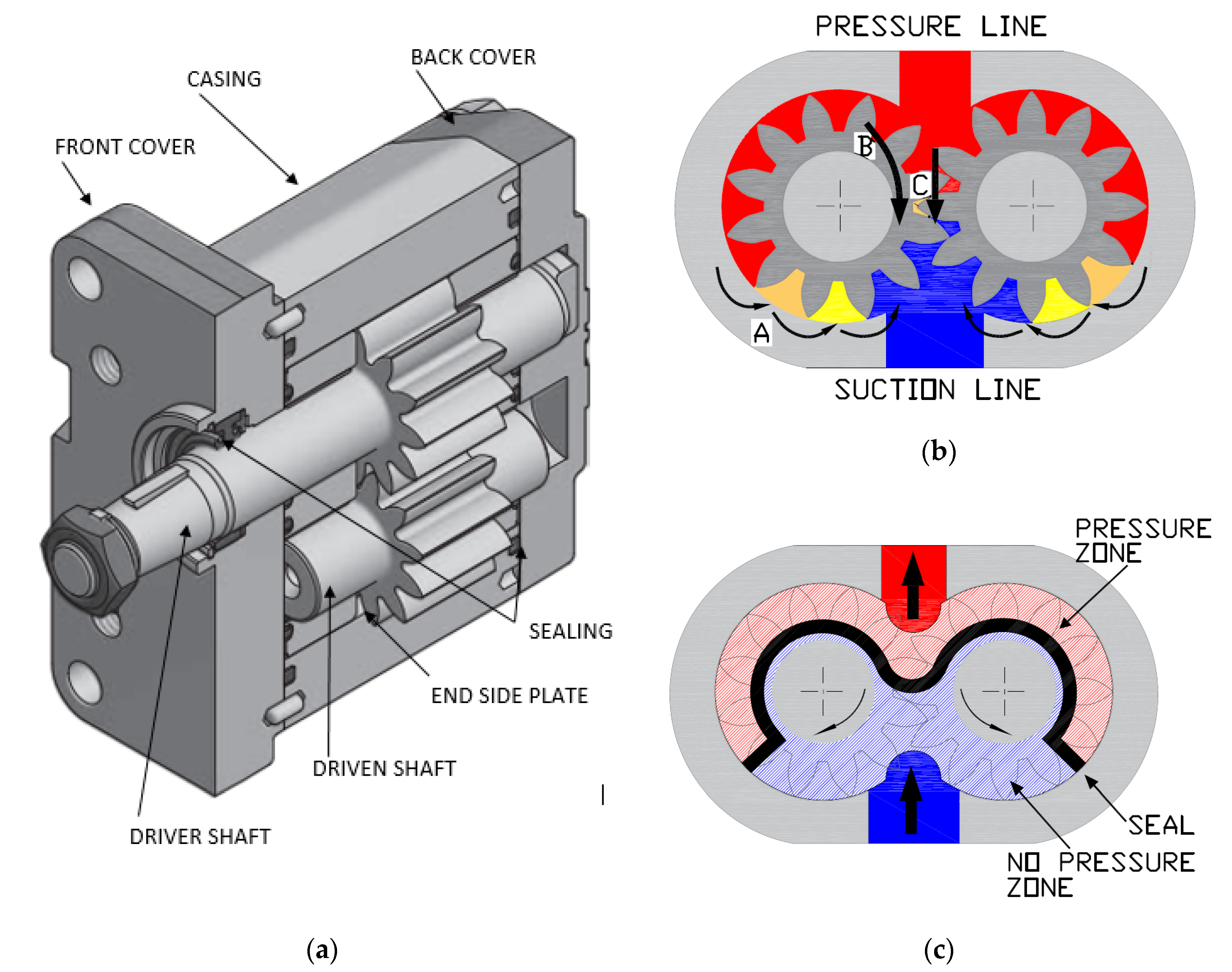
Internal gear pumps and external gear pumps are the two main types of hydraulic gear pumps. Pumps with external gears have two spur gears, the spurs of which are all externally arranged. Internal gear pumps also feature two spur gears, and the spurs of both gears are internally arranged, with one gear spinning around inside the other.
Both types of gear pumps deliver a consistent amount of liquid with each spinning of the gears. Hydraulic gear pumps are popular due to their versatility, effectiveness, and fairly simple design. Furthermore, because they are obtainable in a variety of configurations, they can be used in a wide range of consumer, industrial, and commercial product contexts.
Hydraulic ram pumps are cyclic machines that use water power, also referred to as hydropower, to transport water to a higher level than its original source. This hydraulic pump type is powered solely by the momentum of moving or falling water.
Ram pumps are a common type of hydraulic pump, especially among other types of hydraulic water pumps. Hydraulic ram pumps are utilized to move the water in the waste management, agricultural, sewage, plumbing, manufacturing, and engineering industries, though only about ten percent of the water utilized to run the pump gets to the planned end point.
Despite this disadvantage, using hydropower instead of an external energy source to power this kind of pump makes it a prominent choice in developing countries where the availability of the fuel and electricity required to energize motorized pumps is limited. The use of hydropower also reduces energy consumption for industrial factories and plants significantly. Having only two moving parts is another advantage of the hydraulic ram, making installation fairly simple in areas with free falling or flowing water. The water amount and the rate at which it falls have an important effect on the pump"s success. It is critical to keep this in mind when choosing a location for a pump and a water source. Length, size, diameter, minimum and maximum flow rates, and speed of operation are all important factors to consider.
Hydraulic water pumps are machines that move water from one location to another. Because water pumps are used in so many different applications, there are numerous hydraulic water pump variations.
Water pumps are useful in a variety of situations. Hydraulic pumps can be used to direct water where it is needed in industry, where water is often an ingredient in an industrial process or product. Water pumps are essential in supplying water to people in homes, particularly in rural residences that are not linked to a large sewage circuit. Water pumps are required in commercial settings to transport water to the upper floors of high rise buildings. Hydraulic water pumps in all of these situations could be powered by fuel, electricity, or even by hand, as is the situation with hydraulic hand pumps.
Water pumps in developed economies are typically automated and powered by electricity. Alternative pumping tools are frequently used in developing economies where dependable and cost effective sources of electricity and fuel are scarce. Hydraulic ram pumps, for example, can deliver water to remote locations without the use of electricity or fuel. These pumps rely solely on a moving stream of water’s force and a properly configured number of valves, tubes, and compression chambers.
Electric hydraulic pumps are hydraulic liquid transmission machines that use electricity to operate. They are frequently used to transfer hydraulic liquid from a reservoir to an actuator, like a hydraulic cylinder. These actuation mechanisms are an essential component of a wide range of hydraulic machinery.
There are several different types of hydraulic pumps, but the defining feature of each type is the use of pressurized fluids to accomplish a job. The natural characteristics of water, for example, are harnessed in the particular instance of hydraulic water pumps to transport water from one location to another. Hydraulic gear pumps and hydraulic piston


 8613371530291