
what is a case drain on a hydraulic pump quotation
In this Shop Talk Blog post, we are going to discuss the answers to five very common questions about hydraulic motors: what is a case drain, how do hydraulic motors fail, what exactly is displacement, how are hydraulic motors rated, and how does a hydraulic motor differ from a final drive?
Some people may use the terms hydraulic motor and final drive interchangeably, but they aren"t exactly the same. A final drive usually refers to a hydraulic motor that has a speed-reducing
We"ve only covered five of the most common questions about hydraulic motors. If you have any hydraulic motor questions, why not mention them in the comments? We"d love to hear what kind of topics you"d like to have addressed in future blog posts.
is your partner in providing new or remanufactured final drive hydraulic motors from a single mini-excavator to a fleet of heavy equipment. Call today so we can find the right final drive or hydraulic component for you, or check out our online store to.

A case drain is a specific component of a hydraulic system, its objective is to extend the life of a system and reduce time spent on repairs and maintenance.An unrestricted case-drain line is essential on a piston-type hydraulic motor, whether it has axial, radial or bent-axis design. Most skid steers rely on hydraulic systems to power their front loading arms.
Sometimes referred to as a ‘third line’,a case drain drains back the oil which has leaked past the primary seal, and in doing so, prevents pressure from building up against the outer seal.This oil is then returned to the tank or reservoir.
A case drain will have an in-line case drain filter to prevent contaminants from travelling from the hydraulic motor to the tank. Operating a skid steer without a case drain line could result in a full system failure as the shaft seal will be irreparably blown out, if not installed properly your hydraulic line will not work and in worst cases become damaged beyond repair.
A good case drain makes your hydraulic system more energy efficient and lowers the pressure on the tank, good general maintenance of your hydraulic system results in longer durability for your skid steer and attachments.
A case drain is made up of multiple elements whose materials vary, it’s important to know how to remove and disassemble the case drain in order to understand its function and materials. A case drain filter is contained within an aluminum canister.
To remove the filter make sure to plug the drain lines to avoid losing hydraulic fluid or introducing contamination into the system. Simply unscrew the hex nut to access the filter element.
You may be surprised to find that case drain filters are made from a metal, sintered bronze to be specific. To the naked eye, the sintered bronze looks like one solid piece of metal but is actually thousands of bronze spheres that have been sintered together. Sintering is a heat treatment, like welding or soldering, that imparts strength and integrity to a ‘powdered’ material.
Sintering can determine a filter’s porosity which affects what goes through the filter and what doesn’t. Once sintered, the filter is now porous enough to allow hydraulic fluid to flow through it, yet remains dense enough to capture contaminants like metal and rubber debris which will eventually lead to a total system failure if left unmaintained.
Filters in a hydraulic system maintain fluid cleanliness at a level that maximizes component life. The appropriate cleanliness level is based on factors such as operating pressure and the internal clearances of components within a system.
If your case drain filter is blocked, then the hydraulic pressure of the motor will increase severely which will eventually lead to a myriad of mechanical and hydraulic issues and even a total system failure. Seals can be blown allowing hydraulic fluid and lubricant to leak out and also allowing contaminants to make their way into the skid steer and damage it irreparably.
If the filter in your case drain is no longer bronze in colour and looks mucky or dirty we suggest that you replace it. If your case drain is blocked then its worth dissembling the other filters and drain on the hydraulic system to ensure they have remained clean. It’s highly discouraged to attempt to clean your case drain or its filter.
Even if you had power tools or a heavy duty wire brush you will only move more trapped solids into the filter, clogging it even further. Case drain replacements are cheap when compared to replacing your whole final drive. Case drain maintenance is a key part of maintaining the life of your skid steer, and is often overlooked.
The main disadvantage of installing a filter on your hydraulics system is that back pressure created by the filter can cause total system failure caused by excessive pressure on the case drain if installed improperly
In some cases, case drains are considered optional. The case drain line is for low volume flow to the tank. In theory, by installing a high-pressure shaft seal and two check valves then internal leakage is technically drained into the return line, which is the usual function of a case line.
It has generally been found that systems without case drains often result in failure due to shaft seal leaks. Case drain line installation can be tedious but will eradicate any problem relating to shaft seal leakage.
Oftentimes, if a vehicle doesn’t already have a case drain line fitted, the manufacturer will not necessarily outline the need for hydraulic fluid to be returned to the tank. If you want optimum reliability from your tank and hydraulics then fitting a case drain line is the way to go.
Case drain lines are a very specific component, its use is debated among hydraulics experts - some say you need a case drain and others suggest you don’t. Ultimately, understanding how a case drain works is fundamental to upholding your machines maintenance and making sure that your tools last for a long time.
Many system failures in hydraulics are caused by leaks from the tank. It’s important not to neglect your hydraulics system as it could put you, or your workers, at risk.
Once you know how case drain filters work and what their function is within the hydraulic system of a skid steer, then you can visit your mechanical professional and ask for their opinion on whether you need to install a case filter on your skid steer or not.

On most skidsteer and excavator Hydraulic systems, Hydraulic motors and pumps require a case drain line. Sometimes referred to as a third line, the case drain line will relieve any excess pressure and drain it back to your return line, then into the reservoir. Without a properly installed case drain,
that extra pressure could blow a seal or damage your hydraulic line. For higher flow motors or on piston and gear motors, a case drain line is always required. Although, no matter the size of your motor, a case drain is always a good idea as it will relieve the amount of pressure on your shaft seal, helping to prolong its life. A case drain line
Since most machines have a unique style of coupler, BaumaLight does not include a coupler on our case drain line, although they are available. If your skidsteer is not equipped with a case drain, then it can be field installed.

Often in hydraulic systems, hydraulic motors and pumps run case drain hoses. The reason for this is to drain excess internal oil leakage from the motor. This is certainly critical in a piston motor and pump as the pistons have some internal leakage as they are actually just metal on metal. If no case drain hose is installed then the result will be, at the least, a blown shaft seal, and at worst, a split or damaged housing.
With gear pumps the leakage drains back into the suction hose internally, so no case drain is required. With gear motors and geroller/geroter motors, the oil can drain into the outlet port, however, that means that the oil pressure in the outlet port must not exceed the pressure rating of the seal. If it does, then a case drain needs to be installed. This will then usually mean you can run motors in series without damaging the motor.
If you require assistance with your hydraulic system, motors, pumps, hoses, seals, case drain, oil, lubricants or anything else for that matter, please give us a call on (03) 5382 0574 or call in and see us at Horsham Hydraulics, 84 GolfCourse

One way to troubleshoot a final drive that seems weak is to take a look at the rate of flow from the case drain line. In this Shop Talk Blog post, we are going to review the purpose of a case drain line, look at what case drain flow can tell us about a final drive, and then discuss how to estimate the case drain flow. We"ll finish up by looking at how to evaluate the case drain flow to determine if the problem is your final drive.
When a final drive is damaged or badly worn, however, there will be more internal leakage. This excessive leakage will negatively impact the performance of the final drive and can be the cause of a lack of power. If there is too much leakage, it can be detected by monitoring the flow from the case drain line.
If the rate of case drain flow is greater than it should be, then there is a good probability that you have a problem with that final drive. Examples of too much case drain flow would be flow that is greater on the “bad” side than the “good” side, more than what the manufacturer specifies, or more than a very slow rate of flow). If your final drive"s case drain flow is too much, it should be serviced before things get any worse. On the other hand, if the case drain flow is within normal parameters, then the problem is probably not going to be your final drive and you need to keep investigating.
Investing the case drain flow from a final drive or travel motor can help when troubleshooting what seems to be a weak final drive or travel motor. Just keep in mind that it"s important to investigate all the possibilities before deciding the cause is your final drive motor.
is your partner in providing new or remanufactured final drive hydraulic motors from a single mini-excavator to a fleet of heavy equipment. Call today so we can find the right final drive or hydraulic component for you, or check out our online store to.
You"ll often find case drain filters on skid steer loaders, compact track loaders, and mini-excavators -- especially with brands like Case and Bobcat. How important are those filters? And what happens if they get clogged?
In the context of final drive motors, a case drain line returns any internally leaked hydraulic fluid to the tank on your machine. And before we go any further, keep in mind that
seals on your drive motor start to leak, then grit, sand, and dirt can make their way into your final drive. And if your final drive experiences a catastrophic failure, there is going to be a significant amount of generated contamination that is released. And without a case drain filter, that contamination in your final drive can reach other parts of your hydraulic system. With no filter, a simple drive motor failure can become a very expensive hydraulic system failure.
If your machine has a case drain filter and you don"t replace it often enough, then the hydraulic fluid can"t pass through and pressure builds. And even though the case drain line is designed to be low-pressure, that pressure will get high. And high pressure is always going to look for the weakest point to make its escape.
In most instances, the weakest point in your drive motor will be the seals. The seals will start leaking fluid, and that affects performance and will lead to accelerated wear on key components. Leaking fluid will reduce the amount of lubrication available, which means components will start generating even more contamination.
Failed seals will only relieves the pressure so much. In the worst cases we"ve seen, the cover plate of your motor can split and even fly off at high speed. Obviously, none of this is good.
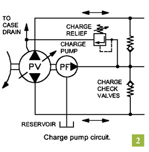
insideyour drive motor. The pressure can go so high that components get displaced. If you"ve got an axial piston final drive motor, the piston ball and shoes are going to be in tension because of the pressure. As that tension continues to build, the shoes can be pulled off. This will wreak havoc in your drive motor, and results in damage that cannot be repaired.
In a radial piston motor, the high pressure can cause the pistons to lift off the cam and then be hammered back into the cam. And if the pressure builds high enough, the pistons and cams can completely lose contact. The final drive motor then freewheels and you won"t be able to control the movement of your machine.
So how often should you replace case drain filters? Here at Final Drive Parts, we recommend that you replace them whenever you are replacing the other hydraulic filters. Adding this to your maintenance routine can save you thousands of dollars in totaled final drive motors.
This website is using a security service to protect itself from online attacks. The action you just performed triggered the security solution. There are several actions that could trigger this block including submitting a certain word or phrase, a SQL command or malformed data.

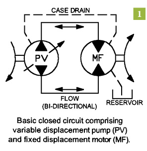
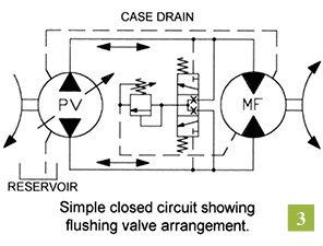
This article is based on a basic circuit with single hydraulic internal gear motor. More complex circuits with multiple motors can have different solutions. Collaborate with your motor supplier for the best results for your particular design.
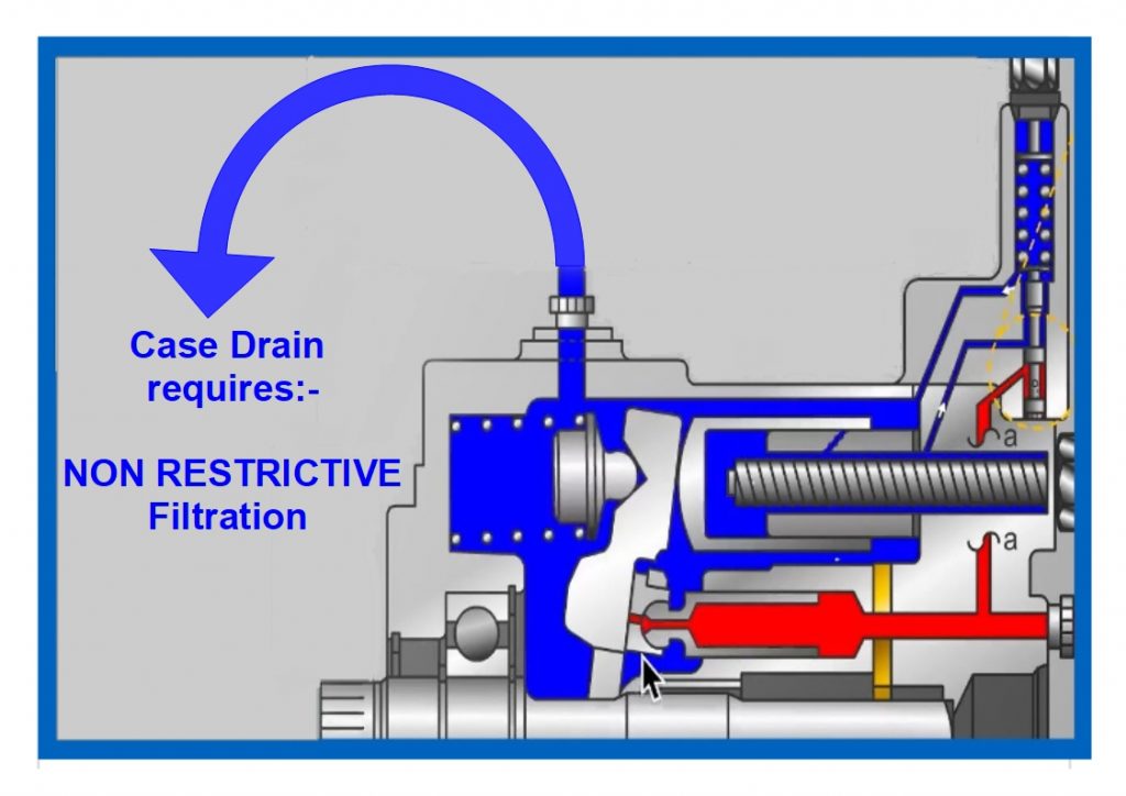
Background: Hydraulic motors have a volumetric efficiency of 90-98%. That means 2 - 10% of the flow entering the motor leaks internally into the case. This is intentional and vital for internal lubrication and clearance between mating pieces.If not allowed to escape, that leakage can build pressure inside the pump case, causing seal leaks or worse, cracks in the cast iron case. The main purpose of a case drain is to allow the internal leakage to escape, but there are other benefits too.
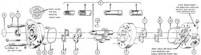
Alternatives: The motor below has a clever solution making the case drain "optional". Two smaller plugs on the rear of this internal gear motor are for check valves.
In the absence of a case drain line, these check valves allow fluid in the case to enter the low-pressure fluid stream. This allows leaked fluid and contamination to exit the motor via the drain line. That might explain why you have seen some hydraulic motors without case drains. However, in a reversing application, that heat and contamination returns to the motor when the direction is reversed.
With a case drain vented to tank, heat and contamination are sent to the reservoir, extending motor life. Even if the case drain port is located on the bottom of the motor, the case will remain filled if the reservoir is above the motor.

PumpMD™ (manufactured by IoT Diagnostics, serviced & distributed by Airline Hydraulics Corp.) provides critical first alerts for your workhorse axial piston pumps. This cost-effective sensor pack allows you to scale across your fleet of pumps and manage schedules around real-time performance data.
Whether you are in the shop, the office, or on the road, never miss a critical alert. Receive instant notifications on pump health (via text, email, and other notifications).
We can configure your PumpMD™ specifications, help place yourorder, or just answer your questions! Connect with an expert by submitting the form below.
This website is using a security service to protect itself from online attacks. The action you just performed triggered the security solution. There are several actions that could trigger this block including submitting a certain word or phrase, a SQL command or malformed data.

This website is using a security service to protect itself from online attacks. The action you just performed triggered the security solution. There are several actions that could trigger this block including submitting a certain word or phrase, a SQL command or malformed data.

The results of the numerical simulation model for the slipper/swashplate friction pair are presented. They are illustrated in terms of pressure and height distribution, average lubricating oil film thickness, slipper tilting angle, supporting stiffness, and location of the centroid of the hydrodynamic lifting force. The slipper considered is characterized by the geometrical parameters listed in Table 2. The nominal operating conditions are taken as the simulation parameters listed in Table 3. The pressure in the piston chamber has a smooth transition between the delivery pressure and the suction pressure. The overshoot and the undershoot of the pressure in the piston chamber are not considered and the hold-down force is considered a known quantity.
Taking the suction stroke for instance, the pressure and the thickness distribution of the oil film are shown in Fig. 3. With increasing case drain pressure, the pressure changes its distribution pattern. The hydrodynamic pressure is significant when the case drain pressure is small, and it is exactly the one that generates the anti-overturning moments. When the pressure in the piston chamber is smaller than the case drain pressure during the suction stroke, the fluid in the pump case, which is a combination of Poiseuille flow and Couette flow, flows backward into the slipper pocket, resulting in increase in the pressure in the slipper pocket. The pressure in the slipper pocket increases and so does the load-carrying force, resulting in increase in the height of the lubricating oil film. As mentioned above, the anti-overturning moments are a function of the height of the lubricating oil film. The higher the case drain pressure is, the larger the height of the lubricating oil film is, and the smaller the anti-overturning moments are. The height of the lubricating oil film thickness increases sharply, followed by breaking of the oil film, and the lubricating oil film is incapable of counteracting the frictional moment and the centrifugal moment. Therefore, reducing the thickness of the lubricating oil film and the tilting angle is very important to prevent the breaking of the lubricating oil film of the slipper/swashplate pair.
The oil film is wedge shaped and the microtilting state varies with the angular position and working parameters. The thickness difference of the three points reflects the tilting state of the slipper. Furthermore, the tilting angle and the average height of lubricating oil film can be obtained based on the thickness of the named three points. Figs. 4 and 5 show the comparison of the average height have of lubricating oil film and the tilting angle α of the slipper, respectively, when the suction pressure is equal to 0.8 bar and the case drain pressures are 1.0 bar, 1.3 bar, and 1.4 bar (1 bar=100 kPa). As shown in Figs. 4 and 5, the pressure profile in the piston chamber during the delivery stroke is larger than that during the suction stroke, and it is assumed that the pressure changes smoothly and there is no pressure overshoot or undershoot in the transition region. It is concluded that the average height of the lubricating oil film increases with the increasing of case drain pressure, and so does the tilting angle of the slipper. During the delivery stroke, the average height of the lubricating oil film is lower than that during the suction stroke. As the case drain pressure is 0.5 bar higher than the suction pressure, there is a prominent increase in the thickness of the lubricating oil film during the suction stroke. Especially when the case drain pressure is 1.4 bar, the simulation failed in the transition region, because the thickness of the lubricating oil film becomes too large, which in turn implies the breaking of the oil film.
During the suction stroke, the average height of the lubricating oil film increases at first and then decreases. This can be explained by the external clamping force acting on the slipper and the change rate of the height of lubricating oil film during the suction stroke. The external clamping force is composed of the force generated by the pressure in the piston chamber, the inertial force, the frictional force, and the retaining force. The inertial force and the frictional force change with respect to the angular position, while the retaining force remains constant and the hydraulic force only increases or decreases in the transition region. The change rate of the height of the lubricating oil film is positive when the external clamping force decreases, and the height of the lubricating oil film starts to increase. When the sum of the inertial force and the frictional force is maximum, the clamping force begins to increase and then the height of the lubricating oil film begins to decrease gradually. This means that the sum of the inertial force and the frictional force pulls the piston/slipper assembly away from the swashplate until their algebraic sum is the maximum at first, and then it helps in pushing the piston/slipper assembly against the swashplate in the suction stroke. Thus, under the combined action of the inertial force and the frictional force, the maximum height of the lubricating oil film is located at the point when the sum of the inertial force and the frictional force is the maximum, and the angular position is located at about 195° for the specified operating conditions in this study; the angular position may change under different pump configurations and operating conditions.
However, when the suction pressure increases, the phenomenon is improved as the height of the lubricating oil film and the tilting angle are within a reasonable range to retain the steady state of the slipper. The graphs of have and α with respect to the angular position are shown, respectively, in Figs. 6 and 7 when the suction pressures equal 1.5 bar and 5 bar. For clarity, only one pressure profile with the suction pressure equal to 1.5 bar is shown in Figs. 6 and 7. Though the slipper can maintain a reasonable distance away from the swashplate, the slipper tilting angle is still too big. When the case drain pressure becomes lower or the suction pressure becomes higher, the average height of the lubricating oil film and the slipper tilting angle decrease obviously.
The reason why the simulation stops in the transition region from high delivery pressure to low suction pressure can be explained by the supporting stiffness. There are hydrostatic force, hydrodynamic force, and squeezing force under the slipper. Therefore, the supporting stiffness is a function of the height of the lubricating oil film, change rate of height of lubricating oil film, tilting angle of slipper, case drain pressure, and pressure in piston chamber. It can be calculated by the sum of the supporting stiffness of each grid under the slipper. The supporting stiffness is shown as
where M and N are numbers of units along the radial and circumferential directions, respectively; subscript i stands for the ith control unit. Fli=piAi is the lifting force of an arbitrary unit, pi is the pressure of the arbitrary volumetric control unit, Ai is the area of the arbitrary unit, and hi is the height of the lubricating oil film of the arbitrary unit.
For simplicity in working with dimensionless values, the supporting stiffness in dimensionless form is used in this study. The dimensionless cell lifting load can be written as \({\overline F _{1i}} = {\overline p _i}{\overline A _i}\) where \({\overline p _i} = {p_i}/{p_{\rm{d}}}\) is the dimensionless pressure of an arbitrary unit, \({\overline A _i} = {A_i}/R_{\rm{s}}^2\) is the dimensionless area of the arbitrary unit, \({\overline h _i} = {h_i}/{R_{\rm{s}}}\) is the dimensionless oil film height of the arbitrary unit, and \(\overline J = J/({p_{\rm{d}}}{R_{\rm{s}}})\) is the dimensionless supporting stiffness.
The supporting stiffness can retain a positive value due to the squeezing effect and the hydrodynamic effect, even if pL is larger than the pressure in the piston chamber during the suction stroke. The supporting stiffnesses under different conditions are shown in Figs. 8 and 9. The actual supporting stiffness is a dynamic value over the pump operating cycle. As can be seen from Figs. 8 and 9, the supporting stiffness is positive if the case drain pressure remains in the reasonable numerical range. The supporting stiffness has little change during the delivery stroke under different case drain pressures for the reason that the slipper remains in a stable state as can be seen from the tilting angles shown in Figs. 5 and 7. In the transition region, the supporting stiffness changes evidently and there exists a minimum value in Figs. 8 and 9. Then, the supporting stiffness begins to increase with increasing clamping force due to the inertial force and the frictional force, as well as the decreasing height of the lubricating oil film. The supporting stiffness during the suction stroke decreases with the increase of the case drain pressure shown in Fig. 8, while the supporting stiffness is improved with the increase of suction pressure shown in Fig. 9.
If the case drain pressure is 0.5 bar higher than the suction pressure, the minimum supporting stiffness decreases, which means the load-carrying capacity that counteracts the varying clamping force becomes weak. If the difference between the case drain pressure and the suction pressure is larger than 0.5 bar, the lubricating oil film cannot resist the change of the clamping force, resulting in the extremely large height of the lubricating oil film thickness, as shown in Fig. 4.
From the analysis above, it is quite clear that the slipper cannot guarantee a good load-carrying capacity when the case drain pressure is 0.5 bar larger than the suction pressure. This unstable behavior can result in inadequate efficiency of the axial piston pump. As mentioned, the slipper is tilted due to tilting moments. The hydrostatic pressure is symmetrical about the x- and the y-axes and does not generate anti-overturning moments. Therefore, only the hydrodynamic pressure generates the anti-overturning moments. The geometrical location of the resultant hydrodynamic lifting force can be determined by finding its centroid. Here, a design criterion is put forward.
where Ex and Ey are the geometrical locations of centroid of hydrodynamic lifting force, Er is the distance between centroid of hydrodynamic lifting force and slipper center. \({E_x} = - {M_{\rm{f}}}/{F_{{\rm{dl}}}},\quad {E_y} = - {M_{\rm{c}}}/{F_{{\rm{dl}}}}\) and \({F_{{\rm{dl}}}} = {m_{\rm{s}}}\ddot z - {F_{{\rm{ps}}}} - {F_{{\rm{sl}}}} - {F_{\rm{r}}}\).
A plane view of the centroid of the equivalent hydrodynamic lifting force is given in Figs. 10 and 11. It is obvious that the centroid of the hydrodynamic lifting force is located in the fourth quadrant, which is consistent with the position of the minimum oil film height shown in Fig. 3.
The distance between the centroid of the hydrodynamic lifting force and the bottom center of the slipper is shown in Figs. 12 and 13. The centroid of the hydrodynamic lifting force is located near the bottom center of the slipper during the delivery stroke, and it moves out during the suction stroke. The maximum Er is located at about 195°, where the clamping force is the smallest and the height of the lubricating oil film is the largest. As the case drain pressure increases, the centroid of the resultant hydrodynamic lifting force goes outward of the slipper sealing land. When the case drain pressure is 0.5 bar larger than the suction pressure, the centroid of the resultant hydrodynamic lifting force is located nearly at the edge of the slipper sealing land, especially for the low suction pressure, as shown in Fig. 12. If the difference between the case drain pressure and the suction pressure is more than 0.5 bar, the centroid of the resultant hydrodynamic lifting force is located out of the slipper sealing land. This phenomenon is impossible in practice, resulting in termination of the simulation. This unstable behavior is clearly due to the inability of the slipper to find an equilibrium position. Accordingly, such a harmful working condition should be avoided. The slipper can operate normally without severe tilting only when the centroid of the hydrodynamic lifting force is located within the outer radius of the slipper.

This website is using a security service to protect itself from online attacks. The action you just performed triggered the security solution. There are several actions that could trigger this block including submitting a certain word or phrase, a SQL command or malformed data.
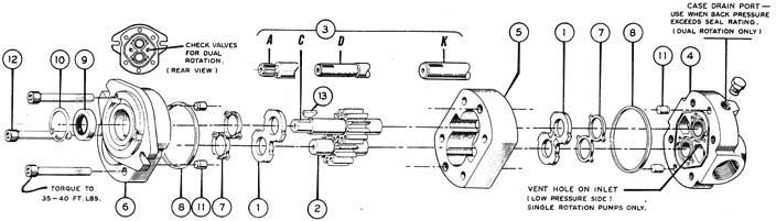
Heavy duty iron castings for higher working pressures. 4-bolt design places all four assembly bolts within the area of greatest internal pressure, which maintains perfect alignment and thus eliminates any decrease in efficiency at high pressures. This greatly reduces internal distortion and the resulting wear of internal parts. Deflecting pressure-balanced wear plates maintain high volumetric efficiencies and minimize mechanical losses. Pressure-lubricated roller bearing design makes these units relatively insensitive to contamination and also makes the units fully repairable.
www.powermotiontech.com is using a security service for protection against online attacks. An action has triggered the service and blocked your request.
Please try again in a few minutes. If the issue persist, please contact the site owner for further assistance. Reference ID IP Address Date and Time 8bf2006c85a66667641f5dd58dcb3d35 63.210.148.230 03/07/2023 05:41 AM UTC
With so many different manufacturers and products, we cannot provide specific performance details or recommendations. Instead, we will highlight the important factors in each particular design type, but users must check the manufacturer"s datasheet to compare how well different products perform.
1.Cleanliness limits e.g. the level it needs from the system to work reliably and the best it will allow the system to run at, considering the duty at which it will work. Users should also consider what the consequences will be if the pump was to fail e.g. what would be the nature of the debris released during a typical failure. Does filtration need to be improved?
2.What is the minimum suction head requirement? Can pump suction conditions be improved, particularly when starting from cold? Will units operate at altitude which could increase potential issues.
3.What is the predicted life of the pump under the expected duty cycle? Remember that rated life predictions are based on normal operating conditions, which will not be the same for all installations. Have peak pressure or continuous pressure ratings been used?
7.Is planned maintenance appropriate e.g. is the fluid health checked or could it be damaged by aging or local operating conditions, therefore, reducing the life of the pump? Can the temperature of the case leakage line be monitored as a way of predicting pump damage?
8.Could volumetric efficiency drop at particular working speeds, temperatures, or pressures? Is there enough installed power to operate under the worst conditions or are certain environmental operating limits required.
10.Does the pump require a separate case leakage line? And if so what is the maximum pressure permitted. It"s always recommended to have a motor case leakage line even it the pump version doesn"t. Motor return lines are likely to exceed shaft seal limits and therefore without a drain line, high case pressures will cause seal failures or reduced life.
Hydraulic pumps are used in almost every type of production system, from plastic mold injection machines to the common conveyor belt. With proper maintenance, most hydraulic pumps will operate smoothly for years, but even with proper maintenance, the pressure inside these devices will eventually cause failures that need to be addressed as soon as possible. The way to avoid total system failure is by monitoring your pumps and looking for the following warning signs.
Liquids should remain in the tubes that were designed for them. If you notice any liquids anywhere else inside the pump, you have a problem. A line may have a break, or a seal may be loose. No matter what the case, an interior leak means your pump has gone bad.
Have you discovered liquid on the outside of your pump? This means either an interior leak has worsened or there could be a leak on the HPU that the pump is mounted to. This leakage results in reduced pressure in the system and immediate action is required to repair and salvage the pump. Leaking reduces the pressure, which increases the temperature of the system. This affects the viscosity of the oil, reducing the pressure in the system.
Increased fluid temperatures can be the result of the system’s inability to dissipate heat. In most systems, heat within the fluid dissipates through the fluid in the reservoir and a heat exchanger. Heat can cause the fluid to thin, which prevents proper lubrication and may cause pump leaks, reducing pump efficiency and system performance.
Hydraulic fluid that has a milky appearance is a clear indication of water contamination. One source is condensation buildup on the walls of the fluid reservoir as a result of temperature changes from warm days to cool nights. Water contamination can also corrode the pump and other critical components, which can shorten component life. Periodic fluid changes and draining of the water from the reservoir ensure water removal from the system.
If your seals continuously leak and fail, your pump may be operating with a bent or misaligned rod. Depending on the extent of the damage, a skilled machine shop may be able to repair your existing equipment, allowing you to get the most out of your equipment and minimizing costs.
System moving slow? If performance decreases, this could be a sign that your hydraulic pump is starting to go bad or your system is designed incorrectly. This lack of efficiency indicates a lack of flow.
You never want to let your system run if your pump is suffering from any of these problems listed above because it means your system is on the verge of experiencing pump failure. These symptoms are an indicator that something could be seriously wrong and could result in some expensive damage to your hydraulic system. The hydraulic experts at Pneumatic And Hydraulic Company can help in identifying the warning signs and replacing your pump before the damage becomes too costly.


 8613371530291