
what is a case drain on a hydraulic pump pricelist

?I get e-mails like this all the time. I never find time to read them. I decided to read Issue #30 and I couldn"t put it down. I"ll make time from now on.?
?I just love this newsletter. As a Hydraulics Instructor for Eaton, I make copies and distribute them to my students as I address various topics. Please keep "em coming.?
On most skidsteer and excavator Hydraulic systems, Hydraulic motors and pumps require a case drain line. Sometimes referred to as a third line, the case drain line will relieve any excess pressure and drain it back to your return line, then into the reservoir. Without a properly installed case drain,
that extra pressure could blow a seal or damage your hydraulic line. For higher flow motors or on piston and gear motors, a case drain line is always required. Although, no matter the size of your motor, a case drain is always a good idea as it will relieve the amount of pressure on your shaft seal, helping to prolong its life. A case drain line
Since most machines have a unique style of coupler, BaumaLight does not include a coupler on our case drain line, although they are available. If your skidsteer is not equipped with a case drain, then it can be field installed.

One way to troubleshoot a final drive that seems weak is to take a look at the rate of flow from the case drain line. In this Shop Talk Blog post, we are going to review the purpose of a case drain line, look at what case drain flow can tell us about a final drive, and then discuss how to estimate the case drain flow. We"ll finish up by looking at how to evaluate the case drain flow to determine if the problem is your final drive.
When a final drive is damaged or badly worn, however, there will be more internal leakage. This excessive leakage will negatively impact the performance of the final drive and can be the cause of a lack of power. If there is too much leakage, it can be detected by monitoring the flow from the case drain line.
If the rate of case drain flow is greater than it should be, then there is a good probability that you have a problem with that final drive. Examples of too much case drain flow would be flow that is greater on the “bad” side than the “good” side, more than what the manufacturer specifies, or more than a very slow rate of flow). If your final drive"s case drain flow is too much, it should be serviced before things get any worse. On the other hand, if the case drain flow is within normal parameters, then the problem is probably not going to be your final drive and you need to keep investigating.
Investing the case drain flow from a final drive or travel motor can help when troubleshooting what seems to be a weak final drive or travel motor. Just keep in mind that it"s important to investigate all the possibilities before deciding the cause is your final drive motor.
is your partner in providing new or remanufactured final drive hydraulic motors from a single mini-excavator to a fleet of heavy equipment. Call today so we can find the right final drive or hydraulic component for you, or check out our online store to.

In this Shop Talk Blog post, we are going to discuss the answers to five very common questions about hydraulic motors: what is a case drain, how do hydraulic motors fail, what exactly is displacement, how are hydraulic motors rated, and how does a hydraulic motor differ from a final drive?
Some people may use the terms hydraulic motor and final drive interchangeably, but they aren"t exactly the same. A final drive usually refers to a hydraulic motor that has a speed-reducing
We"ve only covered five of the most common questions about hydraulic motors. If you have any hydraulic motor questions, why not mention them in the comments? We"d love to hear what kind of topics you"d like to have addressed in future blog posts.
is your partner in providing new or remanufactured final drive hydraulic motors from a single mini-excavator to a fleet of heavy equipment. Call today so we can find the right final drive or hydraulic component for you, or check out our online store to.

In this article, I will be revealing the "formula" that I apply whenever I need to perform a "quick and dirty" test of a pump by evaluating its drain flow rate. It"s called the "five plus five rule".
Please note that the purpose of this formula is to establish a ballpark figure that can be used to sound an alarm if the drain flow rate is above it, but in no case to affirm that a given pump is "safe and sound" if the drain flow is below it. Not all pump malfunctions are reflected in the increase of the drain flow, you know.
You may ask - why bother measuring drain flows at all? For convenience! When you troubleshoot a hydraulic system with unknown service history and want to do a quick check of the pump, measuring its drain flow is often much easier to perform than measuring its output flow simply because the drain lines have better access. Also, since measured flow rates are smaller, alternative flow measuring methods that don"t require special gear can be used.
On another note - the "five plus five rule" can only be applied to "common" medium-sized axial-piston variable displacement open-loop hydraulic pumps, in which the only two sources of the drain flow are the rotary group internal leakage, and the leakage associated with the displacement control. Obviously, if a hydraulic pump has a built-in flushing valve, or a pilot pressure pump that is venting into the case, or an internal connection between the case and the suction line, this rule can"t be applied.
The rule goes as follows (remember - we"re establishing a ballpark figure here, and we only do this because we have no manufacturer recommended base-line available to us, or we simply don"t feel like looking it up):
Step 1 - take the displacement of your pump and multiply it by the rated rpm - the result is the theoretical nominal flow. If you"re not sure what the rated speed of your pump is, look up any similarly sized unit in a catalog of one of the Big Four (Rexroth, Parker, Eaton, or Danfoss) - pumps are pumps, and nominal values always boil down to roughly the same figure across similarly sized models. For example - in the case of a 100 cc open loop pump of an unknown brand with what seems like a PC and LS control I would estimate 100 x 2200 = 220 l/min.
Step 2 - Calculate five percent (this is the first "five" of the rule) of the figure from step 1 - this is the ballpark figure for your drain flow at nominal pressure and nominal speed. In our case - 220 x 0,05 = 11 l/min.
Step 3 - Consider the pump control and adjust your "ballpark" drain value - if the pump has a mechanical torque limiter control, you can add 2 l/min to the drain flow - torque controls always add to internal leakage, if there"s a bleed orifice in the LS control - maybe add another liter. Take a sheet of paper and write the value down with the word "Good" to the left of it. In our example there"s no torque control, we"re not sure about the orifice, so we"re keeping the 11 l/min. Our sheet of paper reads: "Good: 11 l/min"
Step 4 - Take the figure from step 3 and add the five percent from step 2 (this is the "plus five" part of the rule). In our example - 11 + 11 = 22. Write the result on the same sheet of paper with the word "Bad" to the left of it. So, now our paper goes like this: "Good: 11 l/min ... Bad: 22 l/min".
Step 5 - Find a way to load the pump to its nominal pressure without de-stroking (reaching the PC setting value) and then measure the drain flow rate. Draw conclusions by using the chart you just created:
Flow rate between the "Good" and the "Bad" - the pump has wear, but can probably still operate for some time. The closer to "Bad" the more wear the pump has (In our case - between 11 - 22 l/min). Schedule an overhaul.
Flow rate close to or above the "Bad" - the pump should be overhauled immediately (In our case I"d estimate anything above 18 l/m as very concerning, and above 22 l/min as unacceptable).
If you want a more scientific way to guesstimate a baseline for the drain flow rate evaluation - I suggest consulting, once again the big four. Well, not four - three - Eaton, Parker, and then Danfoss. Rexroth is kind of way behind and I"ll explain why.
Eaton does a great job presenting drain flow graphs in their open-loop pump catalogs. This one is for the 620 series. I strongly advise studying it in detail and using it as a universal reference. Parker is close behind, and Danfoss is in third place, with mere volumetric efficiency graphs. Rexroth, unfortunately, is looking at the podium wishing one day he"d be there... You"ll have to look really hard to find this information in their catalogs. Just use the Eaton figures, these charts are beautiful.
Drain flow evaluation should be performed with the oil at rated viscosity, so make sure you know which oil the system is using and that the temperature is right. I like 50C (about 120F) - a nice round number that works for most hydraulic systems with mineral oil.
Drain flow does increase with speed, but only to a small degree (in fact - for some pumps it can be almost constant above a certain speed) so the volumetric efficiency of a hydraulic pump increases with speed.
The typical volumetric efficiency of a new axial piston pump is about 95% at rated speed and pressure. Don"t forget that the key word here is "rated". If we ran our pump at 1000 rpm, the 11 l/min drain flow rate would mean volumetric efficiency of less than 90%, which could be falsely interpreted as a sign of a worn-out pump.
When the pressure compensator is de-stroking the pump - the drain flow increases, sometimes by another 2,5 percent of the rated full flow, it"s important to know and expect that. Again - Eaton"s graphs illustrate this perfectly.
The "five plus five" rule is not the best method to detect a problematic pump - it"s a method. Another tool in your toolbox. You should decide when and if to use it. If I gave you a knife to cut bread, don"t blame me if you accidentally chop off one of your "appendages".

This article is based on a basic circuit with single hydraulic internal gear motor. More complex circuits with multiple motors can have different solutions. Collaborate with your motor supplier for the best results for your particular design.
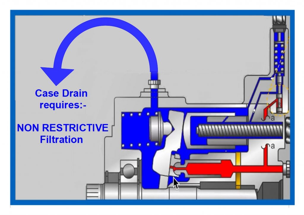
Background: Hydraulic motors have a volumetric efficiency of 90-98%. That means 2 - 10% of the flow entering the motor leaks internally into the case. This is intentional and vital for internal lubrication and clearance between mating pieces.If not allowed to escape, that leakage can build pressure inside the pump case, causing seal leaks or worse, cracks in the cast iron case. The main purpose of a case drain is to allow the internal leakage to escape, but there are other benefits too.
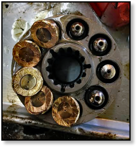
Alternatives: The motor below has a clever solution making the case drain "optional". Two smaller plugs on the rear of this internal gear motor are for check valves.
In the absence of a case drain line, these check valves allow fluid in the case to enter the low-pressure fluid stream. This allows leaked fluid and contamination to exit the motor via the drain line. That might explain why you have seen some hydraulic motors without case drains. However, in a reversing application, that heat and contamination returns to the motor when the direction is reversed.
With a case drain vented to tank, heat and contamination are sent to the reservoir, extending motor life. Even if the case drain port is located on the bottom of the motor, the case will remain filled if the reservoir is above the motor.
PumpMD™ (manufactured by IoT Diagnostics, serviced & distributed by Airline Hydraulics Corp.) provides critical first alerts for your workhorse axial piston pumps. This cost-effective sensor pack allows you to scale across your fleet of pumps and manage schedules around real-time performance data.
Whether you are in the shop, the office, or on the road, never miss a critical alert. Receive instant notifications on pump health (via text, email, and other notifications).
We can configure your PumpMD™ specifications, help place yourorder, or just answer your questions! Connect with an expert by submitting the form below.

The images on the data sheet show motors that look like Parkers F2 motor, however Sub-Atlantic sell conversion kits to fit many standard motor flanges. That means that the motor could be one of many models.
The ports are,as you say #8(1/2" BSP). You cannot reduce the port size to #4(1/4" BSP). If you do, you will surely blow the shaft seals on the motors. The casing drain ports is sized acording to the amount of oil flow that the manufacturers expect to see. Reducing it will force the case pressure up. If you have have two motors, the port in the manifold needs to be #16(1" BSP). If you have 4 motors you will need #32 port(2" BSP).
You cannot cut corners, if you refer to any bent axis motor data sheet you will see that it says the casing drain must be piped seperately using the correct size piping. If you do anything less, it is only a matter of time before the shaft seals are blown out. Don"t be guided by what people believe the flow may be, follow the size of the casing drain port on the motor. That way if there is a failure, there will be some warranty support.
Ultimately it is up to you to decide what to do, but if the motors start spilling oil, fingers will start pointing in your direction as you are the person who designed the manifold. From experience it is not nice when environmental investigators start asking difficult questions.

With so many different manufacturers and products, we cannot provide specific performance details or recommendations. Instead, we will highlight the important factors in each particular design type, but users must check the manufacturer"s datasheet to compare how well different products perform.
1.Cleanliness limits e.g. the level it needs from the system to work reliably and the best it will allow the system to run at, considering the duty at which it will work. Users should also consider what the consequences will be if the pump was to fail e.g. what would be the nature of the debris released during a typical failure. Does filtration need to be improved?
2.What is the minimum suction head requirement? Can pump suction conditions be improved, particularly when starting from cold? Will units operate at altitude which could increase potential issues.
3.What is the predicted life of the pump under the expected duty cycle? Remember that rated life predictions are based on normal operating conditions, which will not be the same for all installations. Have peak pressure or continuous pressure ratings been used?
7.Is planned maintenance appropriate e.g. is the fluid health checked or could it be damaged by aging or local operating conditions, therefore, reducing the life of the pump? Can the temperature of the case leakage line be monitored as a way of predicting pump damage?
8.Could volumetric efficiency drop at particular working speeds, temperatures, or pressures? Is there enough installed power to operate under the worst conditions or are certain environmental operating limits required.
10.Does the pump require a separate case leakage line? And if so what is the maximum pressure permitted. It"s always recommended to have a motor case leakage line even it the pump version doesn"t. Motor return lines are likely to exceed shaft seal limits and therefore without a drain line, high case pressures will cause seal failures or reduced life.

The ideal in hydraulic system design is to match overall efficiencies to the application performance expectation. This requires MTL Attachments to first match the motor, then to a specific system performance expectation. GPM - PSI - RPM - Overall Tip speed - Cutting Application - type of use.
Both motor types—gear or piston—has a specific performance profile advantages and disadvantages. So, knowing the application performance requirement and which motor type best meets the objective is the first step. Then it’s necessary to evaluate the cost of your motor options vs the applications being used for.
In the end, it all goes back to the application’s performance expectations. Some have a harsher more severe duty cycles, while others do not. If, for example, you consider running a std flow Gear type in a high impact more than 1.5 hours of continuous use application, the life of the motor will be less than the life of a Higher Flow Rated Gear motor that is designed to operate in those types of environments. It is important to understand what operating pressures and flows are required for the motor selected to achieve the application performance expectations, this is where MTL Attachments surpasses all of our competitors - we have the experience of thousands and thousands of cutters vs model of skid steer - vs applicational use, We match your needs the best we can to your type of requirements - Both Piston and Gear type.
Each motor type has its own set of applications where they are a better choice than others. For example, if a small gear motor designed to operate at a max of 3,000 psi and 700 rpm is put into an application that requires it to run consistently at 3,000 psi and 700 rpm, the motor will be running in a maximum over-stressed condition and have a reduced life—even though it is technically within its ratings. The better motor choice would be a motor with higher ratings that will live longer in the application. Granted, there is a greater cost in going with a higher rated motor. The final decision always will depend on what is required in terms of application performance and motor life versus where you want to be with cost.
Come in two varieties—the gerotor/geroller or orbital and external spur gear designs. Orbital styles are classified as LSHT motors; They consist of a matched gear set enclosed in a housing. When hydraulic fluid is moved into the motor, it causes the gears to rotate. One of the gears is connected to the motor output shaft, which produces the motor’s rotary motion. Key features include:
• Cutting times are 60% to 70% of The Piston options (depending on cooling efficiency of your skid steer- most gear type motors can operate up to 2 hrs straight at WOT - wide open throttle / full power before needing to cool down) - i.e. Gear Motor cutting at 23 gpm at 80 degrees temp, in a high stress environment would be approx 2 hours of straight use before needing to cool down to provide maximum efficiency again.
Radial piston motors, such as the Industry leading - SAI-FS series motors are LSHT (low speed High Torque) classified. These motors are designed with pistons arranged perpendicular to the output shaft. Typically, the pistons will ride against a cam, which is mechanically connected to the output shaft. The pistons will force the cam to rotate as hydraulic fluid enters the motor.
• Piston motors CAN NOT be stalled - causing a piston type motor to come to an abrupt stop could cause a safety oil seal to relieve and need to be replaced before continuing use. - Typically less than 45 min and $40 to $60 if using the High Pressure VITON style double lip seal. See update below for our MTL cutters upgrade as of 2021.
*******Atmosperic Vent Valve - MTL cutters only - as of 2021 we now started using the AV vent on all our piston motors that now prevent the lower seal from ever blowing - this is a game changer and a result of a constant strive for improvements that we try to achieve here at MTL.******
*****Manual “H” Valve models use an external circulatory valve to provide the highest amount of power and torque yield and have been widely used in Cutters for many years - yet are more susceptible to the stalling issue if abused or continual lack of regard for rpm maintaining.
*****Automated valve models provide some extra safety layers to the stalling issue but do not provide a 100% uncertainty. Using both pressure and return relief valves they use a small percentage of the power available to provide a high percentage of stalling situations, results are extremely impressive - yet the cost is slightly higher than the circulatory valve option.
• Piston motors require a case drain option, these types of motor MUST vent pressure build up via the case drain line - failure of the case drain line would result in the safety seal relief on the motor. ALL Hydraulic lines MUST be connected and remain connected during any and all use (if the cutter is turning - the lines must stay connected - even if the machine is shut off and you are out of the cab) Damaged, Pinched, disconnected or defective couplers can result in the safety valve replacement .
All safety valve replacements are NOT covered under warranty - this is an indicator that the unit has been put in a situation mentioned above- While this is listed as a CON for the PISTON models - one may think of this as the ultimate PRO or insurance policy for the motors, offering protection to the motor in every possible unforeseen situation - yet not causing catastrophic damage to your motor.
Think of a PISTON motor much like that of a centrifugal clutch on a chain saw, a motor with very high output and very quick recovery spin up times, just like the chain saw - should you stall or run down in RPM to much you will cease to have any power or output. This option provides the absolute highest and most efficient hydraulic power conversion to horse power available on the market to date. Commercial, experienced or operators that have a great attention to details and surroundings find this to be the only option they will consider, with the AV VENT we run now as of 2021 on all MTL piston motors even homeowners or first timers can experience the ABSOLUTE best power advantages offered in the industry.
Think of a GEAR Motor much like that of a Air Cooled Diesel Engine - A workhorse - Plain and simple operation - no speedster - not the ultra fast recovery times of the Piston - Not the HP output of the Piston and - Not the efficient heat dissipation of the Piston - but the longest proven track record of reliable continuous use motors in various industries - as long as it is not over-stressed by extreme heat fatigue of prolonged cutting times. This Gear Motor option requires the least amount of attention to detail, listening for RPM declines, hose or coupler issues etc. Homeowners, weekend users, first time no experience users and Commercial users where prolonged cutting times are not an issue would most likely be the obvious choice, now since March of 2021 we have included our AV vent on all Piston Motors and developed basically a bulletproof Piston Option on our cutters allowing ALL customers to experience the best motors in the industry.


 8613371530291