
what is hydraulic pump cavitation brands
A variety of factors within the system could produce such a vacuum. When fluid enters the hydraulic pump and is compressed, the small air bubbles implode on a molecular level. Each implosion is extremely powerful and can remove material from the inside of the pump until it is no longer functional. Cavitation can destroy brand new pumps in a matter of minutes, leaving signs of physical damage including specific wear patterns. The process of cavitation destroying a hydraulic pump also has a distinctly audible sound similar to a growl.
The good news is that cavitation need not be a common problem in hydraulic systems. A few design flaws are largely responsible for causing cavitation: improper configuration of pump suction lines and the use of suction-line filters or strainers. To prevent these causes of cavitation and ensure the creation of a quality hydraulic system with a long, productive life, seven design elements must be properly executed:
In addition to improper pump suction-line configurations, suction-line filters or strainers can be a leading cause of cavitation. These filters are often placed under the oil reservoir, and thus are rarely serviced properly due to their inconvenient location. With this configuration, the entire reservoir has to be drained and disassembled in order to the reach the filter, so this necessary task is often neglected. As the filter becomes increasingly full of debris over time due to a lack of regular maintenance, not enough fluid will flow to the pump, and cavitation will occur.
Such causes of cavitation can be prevented using a series of correct design practices based on the specific needs and functions of a hydraulic system. Many systems are unique, so an experienced engineer with a firm grasp on each of these concepts must ensure the proper installation and maintenance of a hydraulic system.
Air bubbles in hydraulic fluid first originate is in the reservoir. New oil being introduced into the reservoir can cause turbulent flow, stirring up the oil and introducing air into the fluid, which can lead to cavitation. A correctly designed reservoir tank will prevent this issue.
The size of the tank and the amount of fluid that needs to rest before being extracted depends on the amount of system flow. However, a minimum 4 to 1 tank capacity to flow rate ratio is recommended — four times the oil available in the reservoir at any given time than is needed for extraction to send to the pump. This ensures that the pump will receive clean oil and the oil spends enough time in the reservoir for air bubbles and impurities to work their way out.
Beyond properly designing the reservoir itself, it’s important to include the correct accessories to ensure proper functionality. The breather filter is perhaps the most important accessory for maintaining the correct conditions for the hydraulic fluid in the tank.
When fluid is drawn from the reservoir by the pump, and an equal amount isn"t returned, the oil level will drop. To regulate the pressure and prevent forming a vacuum, air needs to be introduced to the tank to occupy the extra volume created upon removal of the oil. A breather filter performs this function, which helps avoid cavitation.
Incorrect design and configuration of suction lines is the primary cause of cavitation in hydraulic systems. For this reason, it’s crucial to use correct design practices when designing the suction lines, such as using the proper line size, minimizing fittings on the line, and properly sizing the ball valve to handle the amount of flow through the line.
The size of a suction line should be large enough for the liquid’s area to flow through at the correct rate and in the correct amount. Because the pump needs to be constantly supplied with oil, it becomes obvious how a line that’s too small could prevent this essential function. The exact specifications of a suction line in terms of length and width can’t be determined in a general sense — it requires a skilled engineer with a firm grasp of the process to make the correct decision on this specification.
Another best practice to consider when configuring suction lines is to include a lock on the suction ball valve, preventing it from being accidentally closed or left partially closed during the pump’s operation. Shutting off the flow of a suction line during pump operation will have cataclysmic effects on the system.
For example, the oil can be filtered upon entering the reservoir tank rather than when leaving the tank. Or a off-line (kidney loop) filtration system can be used to pull the oil out of the tank, filter it, and reinsert it before it’s extracted and sent to a hydraulic pump. These solutions allow for greater ease of maintenance and lower the chance of system failure.
A key aspect of a hydraulic system is a pump that’s properly sized to handle the flow rate and amount of fluid in the system. Again, this decision must be made by an experienced engineer with a good understanding of the entire process. A pump’s size can be determined by incorporating several variables of the process into a standard equation while also considering unique application conditions.
Another key element within a hydraulic system is to maintain the proper fluid temperature. If the hydraulic fluid gets too cold, it can become too viscous, increasing pressure drop in fluid lines and eventual cavitation in the pump. On the other hand, overheated hydraulic fluid can become too thin, compromising its ability to lubricate the hydraulic pump.
To regulate the temperature of the fluid, electric heating elements can be placed in the reservoir to keep the fluid at the ideal temperature of 110°F. Hydraulic systems often heat themselves naturally, so it’s also important to monitor for temperatures in excess of 110° and provide a heat exchanger or operate the system at reduced capacity.
Most systems use a flooded suction design, meaning that the pump is placed below the oil level to achieve net positive suction. The oil comes out of the reservoir above the location of the pump, which means gravity is used to assist in creating pressure into the pump and suction line. This represents the ideal configuration for a pump in a hydraulic system.
The alternative to this layout is non-flooded suction, in which the pump is placed on top of the tank. This configuration is often used to save space in a system with a limited footprint, but results in several disadvantages. For instance, the pump has to perform the extra work of pulling the oil up against gravity to create a vacuum and then pump the fluid out, which inherently creates restrictions by working against gravity. Also, certain types of pumps will function poorly in a non-flooded suction layout. In these cases, a charge pump can be used to provide positive pressure in the pump suction line.
If each of these design elements is carefully considered while engineering a hydraulic system, the risk of cavitation damaging or destroying hydraulic pumps should decrease significantly. Latest from Valin"s Blog
The NIST Chemistry WebBook contains a great deal of information regarding the properties of a broad range of chemicals and is helpful for those who deal with chemical processes.In this article, Jon Monsen has outlined the procedure for finding the actual density of a gas using the WebBook.

Although cavitation can occur anywhere in a hydraulic system, it commonly occurs within the suction line of a pump. This will cause excessive noise in the pump – generally a high pitched “whining” sound. However, this excessive noise is only the tip of the iceberg! The real result of this phenomenon is severe pump damage and a decrease in pump life. I have personally seen many instances where a customer was replacing pumps frequently, thinking they were receiving defective pumps from their vendor. In reality, the pump failures were not due to poor pump quality – the failures were occurring because of cavitation.
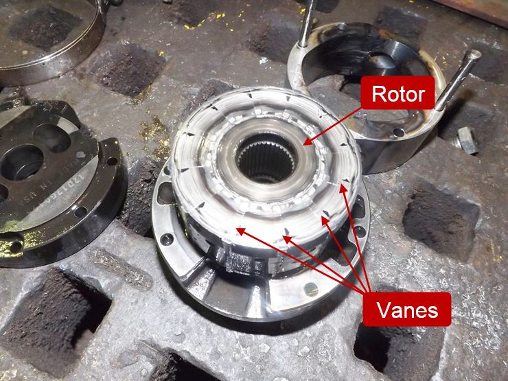
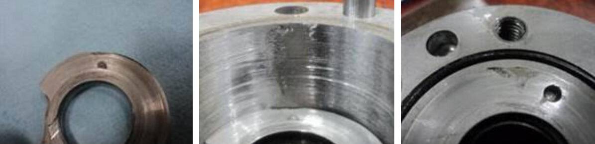
Simply put, cavitation is the formation of vapor cavities in the hydraulic oil. In hydraulic pumps, cavitation will occur any time the pump is attempting to deliver more oil than it receives into the suction (inlet) line. This is commonly referred to as “starvation” and results from a partial vacuum in the suction line. To fully illustrate what is happening when this occurs, we need to discuss vapor pressure. Vapor pressure is the pressure below which a liquid at a given temperature will become a gas, and this pressure varies significantly depending on the liquid. Generally, as the temperature of a liquid rises, the vapor pressure will proportionally increase. Likewise, as the temperature decreases, the vapor pressure will decrease. Most of us know that water will boil (turn to vapor) at 212°F (100°C) at 14.7 PSI (atmospheric pressure at sea level). In other words, the vapor pressure of water at 212°F is 14.7 PSI. If the pressure is reduced, the temperature at which the water boils will be reduced. If the temperature is lowered, the vapor pressure will decrease. In fact, water will boil at room temperature if the pressure is sufficiently reduced! The same principle applies to hydraulic oil, although the vapor pressure will be somewhat different than that of water. The vapor pressure of hydraulic oil is somewhere between 2 and 3 PSI at normal temperatures. In ideal conditions, the pressure in the suction line of the pump will be around 14.7 PSI at sea level. Of course, this pressure decreases with altitude, but sufficient pressure will normally be maintained in the suction line to prevent cavitation of the oil. However, if the pressure in the suction line of the pump is sufficiently reduced to the vapor pressure of the oil, vapor cavities will form. As the oil passes from the suction line to the outlet of the pump, the pressure will increase and the vapor cavities will implode violently. These extremely powerful implosions will cause erosion and premature failure of the pump components. In fact, a brand-new pump can be destroyed in a matter of minutes if the cavitation is severe enough. The picture below shows a rotor and cam ring from a vane pump that had failed due to severe cavitation.
In my 35-plus years of troubleshooting hydraulic components, this is the worst case of cavitation damage I have ever seen. In addition to the usual erosion of the parts, the vanes were actually fused to the rotor slots! Although this is an extreme example, it shows the potential damage to a pump due to cavitation. The good news is that cavitation is preventable and we will look at several conditions that can trigger this phenomenon.

Hydraulic pumps are used in various industries to pump liquid, fluid, and gas. Although this equipment features robust construction, it may fail at times due to various issues. Cavitation is one of the serious issues faced by this equipment. Like all other technical issues, right planning as well as troubleshooting will help avoid this issue to a large extent. What is pump cavitation and how to troubleshoot these it?
It is seen that many times, Strong cavitation that occurs at the impeller inlet may lead to pump failure. Pump cavitation usually affects centrifugal pumps, which may experience several working troubles. At times, submersible pumps may also be affected by pump cavitation.
Non-inertial Cavitation: This type of cavitation is initiated when a bubble in a fluid undergoes shape alterations due to an acoustic field or some other type of energy input.
Suction Cavitation: This cavitation is brought by high vacuum or low-pressure conditions that may affect the flow. These conditions will reduce the flow, and bubbles will be formed near the impeller eye. As these bubbles move towards the pump’s discharge end, they are compressed into liquid, and they will implode against the edge of the impeller.
Discharge Cavitation: Here, cavitation occurs when the pump’s discharge pressure becomes abnormally high, which in turn affects its efficiency. High discharge pressure will alter the flow of fluid, which leads to its recirculation inside the pump. The liquid will get stuck in a pattern between the housing, as well as the impeller, thereby creating a vacuum. This vacuum creates air bubbles, which will collapse and damage the impeller.
Sound: The pump affected by cavitation will produce a marble, rock, or gravel type of sound when in motion. The sound will begin as a small disturbance and its intensity will increase as the material slowly chips away from the surface of the pump.
Metallic Debris: If during the maintenance, you find metallic debris on the filter of the hydraulic pump then it may be a symptom of cavitation. One of the easiest ways to confirm it is to check the filter. If any debris is found, you should clean the entire system, and thoroughly inspect the pump.
Damage: This is one of the most obvious symptoms of cavitation. If you already know that the pump is damaged, you need to remove its filter, open, and inspect it thoroughly. If you find a lot of metal inside the filter, then flush the entire system, and check for damages in other parts, too.
If you notice any of the above-discussed symptoms, the next step would be to identify the causes, and rectify the changes in industrial pumps, otherwise, it may affect other components, too.
Avoid using suction strainers: These are designed to inhibit the ingestion of grime and dirt. However, these strainers do not succeed in their purpose, because they are not designed to entrap large particles. These large particles may get deposited in the flow path, thereby affecting the flow of fluid. The deposition also creates pressure, and produces bubbles, which may lead to cavitation.
Clean the reservoir: A dirty reservoir is one of the most common causes of cavitation. Various types of small and large objects may block the suction tube, and create pressure, thereby causing cavitation.
Use properly sized components: This is one of the important factors of cavitation prevention. If the inlet plumbing is too large, there will be too much liquid flow, which may trigger cavitation. Hence, check with the pump manufacturer to ensure that properly sized components are being used in the pump.
In addition to these preventive steps, you must source hydraulic pumps from a trusted manufacturer or supplier. JM Industrial is one of the industry-leading provider of unused and used industrial process equipment from industry-leading brands. These pumps can be availed at cost-effective prices.
The second leading cause of hydraulic pump failure, behind contamination, is cavitation. Cavitation is a condition that can also potentially damage or compromise your hydraulic system. For this reason, understanding cavitation, its symptoms, and methods of prevention are critical to the efficiency and overall health of not just your hydraulic pump, but your hydraulic system as a whole.
The product of excessive vacuum conditions created at the hydraulic pump’s inlet (supply side), cavitation is the formation, and collapse of vapors within a hydraulic pump. High vacuum creates vapor bubbles within the oil, which are carried to the discharge (pressure) side. These bubbles then collapse, thus cavitation.
This type of hydraulic pump failure is caused by poor plumbing, flow restrictions, or high oil viscosity; however, the leading cause of cavitation is poor plumbing. Poor plumbing is the result of incorrectly sized hose or fittings and or an indirect (not straight or vertical) path from the pump to the reservoir. Flow restrictions, for example, include buildup in the strainer or the use of an incorrect length of hose or a valve that is not fully open. Lastly, high oil viscosity—or oil that is too viscous—will not flow easily to the pump. Oil viscosity must be appropriate for the climate and application in which the hydraulic pump is being used.
The greatest damage caused by cavitation results from the excessive heat generated as the vapor bubbles collapse under the pressure at the pump outlet or discharge side. On the discharge side, these vapor bubbles collapse as the pressure causes the gases to return to a liquid state. The collapses of these bubbles result in violent implosions, drawing surrounding material, or debris, into the collapse. The temperature at the point of implosion can exceed 5,000° F. Keep in mind that in order for these implosions to happen, there must be high vacuum at the inlet and high pressure at the outlet.
Without a pressure condition at the outlet, or discharge side, these vapors merely form voids in the oil that reduce lubrication effectiveness. This results in friction and wear, which while seemingly mild compared to the excessive heat and violent implosions, can become detrimental over time.
Cavitation is usually recognized by sound. The pump will either produce a “whining” sound (more mild conditions) or a “rattling” sound (from intense implosions) that can sound like marbles in a can. If you’re hearing either of these sounds, you first need to determine the source. Just because you hear one of these two sounds doesn’t guarantee that your hydraulic pump is the culprit.
To isolate the pump from the power take-off (PTO) to confirm the source, remove the bolts that connect the two components and detach the pump from the PTO. Next, run the PTO with no pump and see if the sound is still present. If not, it is safe to assume your hydraulic pump is the problem.
Another sign you may be experiencing cavitation is physical evidence. As part of your general maintenance, you should be inspecting and replacing the hydraulic oil filter"s elements at regular intervals based on the duty cycle of the application and how often it is used. If at any time during the inspection and replacement of these elements you find metallic debris, it could be a sign that you’re experiencing cavitation in the pump.
The easiest way to determine the health of your complete hydraulic circuit is to check the filter. Every system should have a hydraulic oil filter somewhere in-line. Return line filters should be plumbed in the, you guessed it, return line from the actuator back to tank—as close to the tank as possible. As mentioned earlier, this filter will have elements that should be replaced at regular intervals. If you find metallic debris, your pump could be experiencing cavitation. You’ll then need to flush the entire system and remove the pump for inspection.
Conversely, if you’ve already determined the pump to be damaged, you should remove the filter element, cut it open, and inspect it. If you find a lot of metal, you’ll need to flush the entire system and keep an eye on the other components that may be compromised as a result.
Once cavitation has been detected within the hydraulic pump, you’ll need to determine the exact cause of cavitation. If you don’t, cavitation can result in pump failure and compromise additional components—potentially costing you your system.
Since the pump is fed via gravity and atmospheric pressure, the path between the reservoir and the pump should be as vertical and straight as possible. This means that the pump should be located as close to the reservoir as is practical with no 90-degree fittings or unnecessary bends in the supply hose. Whenever possible, be sure to locate the reservoir above the pump and have the largest supply ports in the reservoir as well. And don"t forget, ensure the reservoir has a proper breather cap or is pressurized (3–5 PSI), either with an air system or pressure breather cap.
Be sure the supply line shut-off valve (if equipped) is fully open with no restrictions. This should be a “full-flow” ball valve with the same inside diameter (i.d.) as the supply hose. If feasible, locate a vacuum gauge that can be T’d into the supply line and plumb it at the pump inlet port. Activate the PTO and operate a hydraulic function while monitoring the gauge. If it reads >5 in. Hg, shut it off, and resume your inspection.
If a strainer is present in the reservoir, inspect it, and remove any gunk or buildup that may be restricting supply flow. Next, check the inlet (suction) hose for any visible layline (descriptive markings on the hose). The industry standard “suction” hose nomenclature will read 100R4, or possibly SAER4. This will indicate the hose has an inner bladder that’s been vulcanized to a heavy spiral wire.
A hose with an inner bladder vulcanized to a heavy spiral is designed to withstand vacuum conditions as opposed to outward pressure. The layline will also denote the size of the hose (i.d.). You can use Muncie Power’s PPC-1 hydraulic hose calculator to determine the optimal diameter for your particular application based on operating flows.
Another consideration, in regards to the inlet plumbing, is laminar flow. To reduce noise and turbulence at the pump inlet, the length of the supply hose should be at least 10 times its diameter. This means that any type of shut-off valve or strainer at the reservoir should be at least 10 diameters from the pump inlet. A flared, flange-style fitting at the pump inlet can also reduce pump noise by at least 50 percent compared to a SAE, JIC, or NPT fitting.
Selecting the proper viscosity of hydraulic fluid for your climate and application is also critical. Oil that is too viscous will not flow as easily to the pump. Consult your local hydraulic oil supplier for help selecting the optimal fluid viscosity.
By maintaining a regular maintenance schedule, remaining vigilant for any signs or symptoms, and taking preventative measures, the good news is that you should be able to prevent cavitation and experience efficient operation for the duration of your pump’s lifespan.
Poor plumbing is the leading cause of cavitation and can be prevented by selecting a properly sized hose, choosing the appropriate fittings, ensuring the most direct, straight routing from the pump to the reservoir, etc.
Since joining the company in 2007, Ben Gillum has served in various capacities including shipping and receiving clerk, CS assembly, customer service manager, product application specialist, training and education assistant manager, and warranty and returns manager.

While there are several corrective actions that can be taken to resolve a pump cavitation issue within a hydraulic pump, supercharging, or pressurizing, the pump inlet is probably the easiest and most cost effective way of doing this. There are many different benefits to supercharging (forcing flow into the inlet), which creates an artificial positive head or pressure on the pump inlet, reducing the “suck” a pump must have to get oil into the system. Creating a positive head on the inlet will completely eliminate pump cavitation and increase the longevity of the hydraulic pump. There are different ways in which we can supercharge the pump inlet.
Oil viscosity is greatly impacted by the temperature of the oil, with low temperatures causing increases in viscosity which makes it difficult for the oil to reach the pump. Generally, it is best to avoid starting hydraulic systems with oil colder than 40°F (4°C) or putting under load with oil colder than70°F (21°C).
Reservoirs do not always have heaters, especially in the South. Those that do possess available heaters are usually disconnected. Although the damage may not be instantaneous, a pump regularly started using cold oil will eventually fail prematurely.
Investing in a hydraulic oil of high viscosity index base oils with low pour points for wide temperature range applicability, like CITGO’s Mystik® JT-9™ LeakShield® AW Hydraulic Oil, can help prevent such cavitation.
Once a year at minimum, the suction strainer needs to be removed from the reservoir and cleaned. It is prudent to keep in mind that strainers may become blocked for a variety of reasons. If there seems to be a malfunction with a pump—before taking any drastic action, like making replacements—check to ensure nothing has obstructed the suction line.
Every pump has a maximum drive speed. High speeds require higher volumes of oil at the suction ports. If an electric motor is driving the hydraulic pump at speeds over the pump’s rating, you might be gearing up for a crash course in cavitation.
Adequate oil volume is unable to flow into the suction cavity in the pump due to the port’s size, causing the pump to cavitate. Maximum drive speeds can range from as low as 1,200 revolutions per minute (RPM) to as high as 3,600 RPM — so always check drive speed when replacing a pump with that of a different brand or model. Cavitates tend to be rare but being mindful of your pumps’ maximum drive speeds can prevent costly mishaps, such as leaks and other cavitation-induced damage altogether.
Many maintenance technicians confuse cavitation and aeration. In fact, aeration is sometimes referred to as pseudo cavitation. While these two conditions have similar symptoms, their causes are entirely different.
Cavitation is the formation and collapse of air cavities in liquid. When hydraulic fluid is pumped from a reservoir, a low-pressure drop occurs in the suction side of the pump. Despite what many people believe, the fluid is not sucked into the pump but rather pushed into it by atmospheric pressure, as shown in the left illustration below.
The movement of the rotating gears leads to a drop in pressure at the suction line. The resulting pressure difference between the reservoir and the pump inlet causes the fluid to move from the higher pressure to the lower pressure. As long as the pressure difference is sufficient and the flow path is clear, the operation goes smoothly, but anything that reduces the inlet flow can create problems. Whenever the pump cannot get as much fluid as it is trying to deliver, cavitation occurs, as shown in the right illustration below.
Hydraulic oil contains approximately 9 percent dissolved air. When a pump does not get enough oil, air is pulled out of the oil. These air bubbles travel into the pump and eventually collapse and implode when they reach an area of relatively high pressure. The ensuing shockwaves produce a steady, high-pitched whining sound and damage to the inside of the pump. In the early stages, the sound goes undetected in loud plants unless an ultrasonic sensor is employed. These sensors can listen to super high frequencies emitted by the pumps, detecting cavitation before it does too much damage.
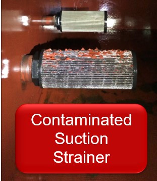
Any increase in fluid velocity can lead to cavitation. Fluid velocity is inversely proportional to the size of the hydraulic line. Most pumps have a suction line that is larger than the pressure line. This is to keep inlet velocity low, making it very easy for oil to enter the pump. Any blockage, such as a plugged suction strainer or filter, can result in the pump cavitating. A contaminated suction strainer is the most common cause of cavitation simply because it is underneath the oil level in the reservoir.
One of our consultants was recently called to a plant in Georgia that had changed five pumps on a machine within a week. The first thing that was noticed was a high-pitched whining sound, which was heard every 20 to 30 seconds. The millwrights had changed the suction line, and although a suction strainer was shown on the schematic, none was found in the line. The machine was then shut down, and the reservoir drained to be cleaned. Guess what was found in the reservoir? The suction strainer, which had been floating around in the oil, was occasionally blocking the suction pipe to the pump. Had there been early detection of cavitation, the plant could have saved a decent chunk of change on all those pumps.
A plugged breather cap is another common cause of cavitation. It can lead to falling pressure in the reservoir. Suction pressure at the pump must drop very low to compensate for this, creating vapor cavities.
At a plywood plant in Oregon, a hose ruptured on the lathe, which resulted in a loss of 150 gallons of oil in the reservoir. After the hose was changed, the lubrication technician removed one of the breather caps to refill the reservoir. While filling the tank, a shift change occurred, and the second-shift lube tech took over. Once the reservoir was refilled, the lube tech installed a pipe plug on the threads where the breather cap was originally located. The result was that one of the pumps on the unit failed within a few hours after startup due to cavitation. After losing two pumps in 24 hours, the pipe plug on the breather opening was discovered.
Extreme oil temperatures can also cause cavitation. High temperatures allow vapor cavities to form with less of a pressure drop, while low temperatures increase the oil’s viscosity, making it harder for the oil to get into the pump. Most hydraulic systems should not be started up with the oil any colder than 40 degrees F or put under load until at least 70 degrees F.
In addition, cavitation may result if the drive speed is too high for the pump, as the pump tries to deliver more oil than it can get into its suction port. If the pump is positioned so fluid must be lifted a long way from the reservoir, atmospheric pressure may be insufficient to deliver enough fluid to the pump inlet, which can cavitate.
Systems at high altitudes are also susceptible to cavitation, as the available atmospheric pressure may be inadequate. It is for this reason that aeronautic hydraulics must use pressurized reservoirs.
Aeration occurs whenever outside air enters the suction side of the pump. This produces a sound that is more erratic than that of cavitation. The whining noise may be augmented by a sound similar to marbles or gravel rattling around inside the pump. If the oil in the reservoir is visible, you may see foaming. Air in the oil can lead to sluggish system performance and even damage the pump and other components.
Aeration is often caused by an air leak in the suction line. Pressure in the suction line is below that of atmospheric pressure, so if there’s a leak in the suction line, oil won’t leak out, but air will leak in. If you suspect an air leak, put oil on all the fittings and connections in the suction line. If the sound of aeration stops briefly, you have found your leak. An ultrasonic gun can also be used to detect leaks.
One of our consultants was asked to diagnose several pump failures on a system at an automotive manufacturing plant. When he arrived at the unit, he heard an erratic high-pitched sound. He also noticed that there were several fittings in the suction line. He had one of the millwrights fill a bottle with oil and squirt it around all the fittings. When oil was applied to one fitting, the pump momentarily quieted down. This fitting had vibrated loose after 12 years on the machine.
A bad shaft seal on a fixed displacement pump is another common cause of aeration. If you suspect a bad shaft seal, spray some shaving cream around the seal. If it is bad, holes in the shaving cream will develop as air enters the pump.
I was once called to a paper mill where foam came out of the log-kicker reservoir shortly after the fixed displacement pump was started. After performing the shaving cream test, I knew the shaft seal was badly worn. Upon further inspection, I found the pump elastomeric coupling was worn, which resulted in wear on the shaft seal.
Incorrect shaft rotation may not be an issue with all pumps, but some will aerate if they are turned backward. Most pumps have a direction of rotation stamped or located on a sticker on the pump housing. Many times when a pump is rebuilt, this sticker is removed. Always check the part number of the new pump to be installed with the old pump. Often a number or letter will indicate whether it is a right-hand or left-hand rotation. If you are unsure, remove the pump’s outlet line and secure it into a container. Never hold this line, as it could be a hazardous situation. Momentarily jog the electric motor. If the pump is rotating in the correct direction, oil will flow out of the outlet port.
Aeration may also result from a low fluid level. The oil level should never drop more than 2 inches above the suction line. If so, a vortex can form, much like when draining a bathtub. This allows air in the suction line, leading to aeration of the pump.
When troubleshooting hydraulic pump issues, make the visual and sound checks first, as these are the easiest to perform. Remember, aeration and cavitation produce different sounds. Usually you can determine the cause of the problem before the first wrench is turned.
Al Smiley is the president of GPM Hydraulic Consulting Inc., located in Monroe, Georgia. Since 1994, GPM has provided hydraulic training, consulting and reliability assessments to companies in t...

Bubbles might not seem very powerful, but the types of bubbles in pumping systems are nothing like the ones you make by waving a wand around with little kids. Tiny bubbles created by changes in pressure inside pumps collapse and create shock waves that occur over and over and the repeated shocks erode the components.
Pumps are designed to work with a full flowing water supply, but in some cases a flooded inlet is not enough to maintain pressure required to prevent cavitation. The inlet, or suction side of a pump is the point of lowest pressure in a given pump.For positive displacement pumps, the lowest pressure occurs just prior to rotor meshing; for centrifugal pumps, lowest pressure is near the eye of the impeller.
Cavitation is possible in all pump types and since its principles are essentially the same, we will focus on centrifugal pumps. The eye is where fluid is drawn into the impeller and where the rotation of the impeller begins to act on the fluid. When pressure acting on the liquid (Net Positive Suction Head Available) is too low, bubbles form, and as the liquid accelerates because of impeller rotation, pressure increases and the bubbles collapse.
Under normal atmospheric pressure conditions, fluids have predictable vapor pressure. As the pressure inside the pump falls below the liquid"s vapor pressure, bubbles form. The bubbles collapse when they reach areas of the liquid where the pressure is above the vapor pressure. In the case of cavitation, this formation and collapse is both rapid and violent.Disrupted or poorly executed processing lines can cause suction or discharge pressure to fall, which leads to cavitation.
At extremely high discharge pressure, some fluid circulates inside the pump instead of discharging. Fluid trapped between impeller and housing at very high velocity cause a drop in pressure, creating the same conditions as for suction cavitation.
Cavitation sounds like marbles or gravel circulating through the pump, pipes, or hoses. The effects of prolonged cavitation are visible on the pump impeller and other components.
Start by identifying the cause of the pressure drop. In many cases moving the pump closer to the fluid source and removing as many bends and valves as possible corrects the problem because each component causes additional pressure drop. When suction lift is too high to maintain pressure, move the pump closer to the fluid source or move the fluid source closer to the pump.
Enlarging suction lines can also be effective. In some obvious cases, a blockage occurs in piping or hoses near the pump. Clear those blockages to resolve the issue.Clean suction lines by clearing debris. Avoid blowing the debris back toward the fluid source because it’s likely to create a blockage again.
Don’t exceed your pump manufacturer’s performance guidelines. Pump curves tell you how much net positive suction head the pump requires, so check your pump’s performance curve to ensure it has the right specifications for your application.
The best way to prevent cavitation is to select the right pump for the application. Cavitation increases as pump head falls or as capacity increases, so selecting the correct pump to maintain a positive margin of NPSHa above NPSHr is the best first move.
NPHS at the inlet depends on atmospheric pressure, friction losses in the suction piping, and flow velocity. A good rule of thumb is for pressure at the pump inlet to be 10% greater than the pump"s specified NPSHr. For example, if NPSHr is 10 feet, NPSHa should be at least 11 feet.
Discharge cavitation occurs when pressure at the discharge end of the pump is too high. High discharge pressure limits the volume of fluid flowing out of the pump, causing high-velocity fluid to recirculate between pump impeller and housing, causing cavitation.
Check filters and strainers. Dirty or blocked filters and strainers generate pressure buildup inside the pump. Setting a maintenance schedule ensures that systems are in place to keep the pump system flowing at capacity.
Evaluate the curve. Consider the job pressure demands and then consider the pump data to see if it fits the application. From there you determine if the pump fits the needed flow rate.
The best ounce of cavitation prevention is pump selection and system design for maintaining pressure and flow. The goal of installation is therefore to maintain net positive suction head available (NPSHa) at greater than net positive suction head required (NPSHr) by considering four key variables:
Physically install the pump so the water flows into the pump suction inlet smoothly.Make sure that the suction lines leading to the inlet of the pump are adequately sloped to ensure that the pump housing is flooded.
Placing the pump at a point that is lower than the water level in the tank from which it pumps, for example, uses the force of gravity to maintain flooded suction, which in many cases prevents cavitation.
Pumps, and especially centrifugal pumps, work most efficiently when the fluid travels in a smooth, laminar flow, and turbulence of any kind reduces pump efficiency, so positioning the pump as close as possible to the fluid source makes sense.
In general, you want 12 cm of straight pipe for every centimeter of pump suction diameter.To maintain laminar flow, connect 5-10 pipe diameters of straight piping to the pump inlet. Do not include elbows, reducers, valves, or strainerswithin the final length of pipework. Connecting an elbow directly to the pump flange, for example, draws fluid towards the outer curve of the elbow instead of directly into the eye of the impeller.
Also, the piping arrangement must not cause strain on the pump casing, so pumps can never support the piping for suction or discharge. Use hangers and supports instead.
Good piping layouts prevent cavitation by helping to maintain constant velocity. Obstructions in piping layouts affect flow velocity, which changes fluid pressure, which can cause cavitation.
While it’s true that some cavitation can have positive purposes, such as for surgical equipment sterilization or to break down pollutants in water systems, it’s not something you want in your processing system, so time spent preventing cavitation is time well spent.
When your pump, pipe, or hose sounds like marbles or gravel are circulating, you"re witnessing cavitation and need to take immediate action or risk severe damage to components. When cavitation does occur, you need a trusted partner that can diagnose the cause, provide a long-term solution, and repair or replace parts that are damaged.
CSI"s pump service and maintenance program is designed to take the irritation and guesswork out of dealing with pump cavitation. Each audit and repair that CSI completes include an evaluation by an OEM-trained pump technician, a report on the findings, and all the materials required to perform the service. Call us today to schedule your next system audit or pump repair!
Central States Industrial Equipment (CSI) is a leader in distribution of hygienic pipe, valves, fittings, pumps, heat exchangers, and MRO supplies for hygienic industrial processors, with four distribution facilities across the U.S. CSI also provides detail design and execution for hygienic process systems in the food, dairy, beverage, pharmaceutical, biotechnology, and personal care industries. Specializing in process piping, system start-ups, and cleaning systems, CSI leverages technology, intellectual property, and industry expertise to deliver solutions to processing problems. More information can be found at www.csidesigns.com.
This guide is intended for engineers, production managers, or anyone concerned with proper pump selection for pharmaceutical, biotechnology, and other ultra-clean applications.

Cavitation is a common mode of wear in hydraulic pumps and control valves. The damage to components more often than not results in severe losses of service life times and flow efficiencies. Understanding the causes behind this phenomenon is the first step in developing solutions to combat its harmful effects.
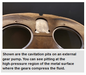
When the local static pressure in a fluid (inlet pressure) falls below the fluids vapour pressure (a characteristic property) at that particular temperature, vapour bubbles form in the fluid/hydraulic oil. Now, when we talk about bubbles, it is difficult to imagine that something so small can do incredible amounts of damage to hydraulic components. The vapour bubbles themselves pose no threat when floating around in the fluid. When the bubbles make it to the high pressure side of the pump/valve, however, they condense instantaneously and the bubbles collapse and produce hydraulic micro-jets which act similar to shockwaves. These micro-jets impinge on the metal surfaces, thereby destroying the material bonds (cavitation damage), and often result in (1) The creation of loud rolling noises (2) Vibration of the pump (3) The delivery of less flow and (4) Pitted erosion (as shown below).
The common causes of cavitation that allow the fluid to have a low static pressure can be grouped into three categories i.e. inlet inadequacies, fluid properties, and pump position.
Inlet inadequacies: These are often the case in systems when there is a restriction to the flow of the hydraulic fluid. Be sure to regularly look out for clogged strainers/filters, too many bends in the inlet line, and/or a collapsed inlet hose. Additionally, during the design and installation stage of your system, ensure the inlet pump lines are correctly sized and not too small.
Fluid properties:If your fluid is in a state that allows it to vaporise easily, the risk of cavitation is increased. This means that there is a presence of water particles and/or the hydraulic fluid is too viscous to be easily forced into the pump as a result of low temperature. Ensure that you use a good quality hydraulic oil, keep it isolated from external wet sources and, if necessary, heat it up before use as you would with warming up your rig’s engine.
Pump position: If your pump is too far away from the reservoir or too far above your reservoir you will have a low suction pressure allowing the formation of cavitation bubbles to occur. Make sure to use a pump with good filling characteristics or with a flooded suction. Alternatively, your design could incorporate a supercharged inlet.
Hydraulic cylinder cavitation is a nightmare for any hydraulic system, leading to a cascading series of damaging issues that will eventually destroy critical (and costly) components within your hydraulic system. While most people associate cavitation issues with pumps and motors, cavitation can also be a problem for hydraulic cylinders. In order to minimize or eliminate cavitation damage, knowledge of how it works and what kind of damage it leads to are good starting points. However, the wisest approach to dealing with cavitation issues is to take preventative measures.
The simplest explanation of cavitation is the presence of gas entrapped within bubbles in a liquid. In the case of hydraulic systems and components like pumps or cylinders, the liquid involved is the hydraulic fluid transmitting pressure. In hydraulic cylinders, the pressure transmitted by the fluid is used for linear actuation that can move thousands of pounds at the press of a button. Obviously, very high pressures are involved.
Bubbles filled with dissolved gases or vapor begin to form and grow when the pressure is close to that of saturated vapor for the fluid’s temperature (e.g., there is localized boiling of the fluid). For a cylinder, all the fluid needs to do is drop below atmospheric pressure for bubbles to form.
When these bubbles collapse on themselves (or implode), the result is noise, heat, serious surface damage, and a negative impact on efficiency and productivity. Essentially, the bubbles generate a powerful mechanical shock that results in microjets impacting nearby metal. That implosion occurs when the bubbles reach an area of low pressure that causes the vapor within them to condense. The metal begins to wear away in a process known as cavitation erosion, cavitation wear, or cavitation pitting.
Cavitation can also occur when air is trapped within the hydraulic fluid (a phenomenon known as aeration). As pressure increases (e.g., as the rod closes in on the end cap in a hydraulic cylinder) the bubbles violently burst. In a hydraulic cylinder, cavitation most often occurs on the cap side of the piston when it is extending quickly, and especially when it is attempting to stop an over-running load. It also occurs when the rod is pointing downward while supporting a heavy tensile load on the end. Some experts would argue that this is not true cavitation, but its effects are the same.
One of the easiest ways to detect cavitation in a hydraulic cylinder is by sound: when cavitation bubbles implode, you can hear them in the form of an intense rattling sound. You will also notice pitting on the surface of parts affected by cavitation; in the case of hydraulic cylinders, it can be found on the surface of the rod and the inside surface of the cylinder.
Cavitation can lead to multiple problems within a hydraulic system as a whole, as well as hydraulic cylinders. These include accelerated wear of critical surfaces, seal failure, generation of unwanted heat, reduction in hydraulic oil quality, and lubrication issues.
One of the most serious problems caused by cavitation is surface wear, sometimes known as pitting. Keep in mind that the vapor bubbles implode at an almost molecular level, releasing a tremendous amount of force over an incredibly small area. That leads to high stresses — stresses high enough to remove metal from surfaces adjacent to those bubbles. The result is highly accelerated wear in the form of surface pitting and internally generated contamination. The metal particles removed from the surface will stay within the system and can cause the formation of even more cavitation bubbles.
Also, keep in mind that surface finish can be an important factor in many applications, and especially with hydraulic cylinders. When selecting an appropriate seal for a hydraulic cylinder, the surface finish of the rod is critical. If the rod is experiencing pitting due to cavitation, it will cause premature wear of the seal. As the seal begins to wear, hydraulic fluid can leak out (reducing performance) and environmental contaminants such as dust and moisture can make their way inside.
The bubble implosions also lead to high temperatures, sometimes reaching up to 5,000°F. In addition, as the surface is damaged, there will be increased friction as fluid flows over. That friction results in not only system losses and lower efficiency but also unwanted heat generation. This is one of the reasons why excessive heat can also be a strong indicator of cavitation.
Because of the high temperatures that can result from cavitation, the hydraulic fluid is very likely to suffer degradation (an overall reduction in fluid quality). Excessive heat and high temperatures will cause the fluid to age more rapidly than normal, seriously affect the additives present, and reduce the viscosity of the fluid.
The presence of bubbles within the hydraulic fluid can also cause a lack of lubrication, resulting in metal-to-metal contact and premature wear. This type of wear takes on a different form than that resulting directly from cavitation implosion and explosion: it will look like abrasions in a pattern consistent with the movement of the metal parts rather than pitting.
One of the means of preventing cavitation lies in temperature control. If the hydraulic fluid is too viscous, pressure drops will become more of a problem; this increase in viscosity can be the result of hydraulic fluid at a less than ideal temperature. In addition, high temperatures combined with low pressures can also cause cavitation, so care needs to be taken to ensure that the hydraulic fluid is as close as possible to an ideal operating temperature. In some instances, this can be as simple as insulating hydraulic pipes against direct sunlight.
Piping losses can contribute to cavitation and result from issues such as the use of too many fittings, a collapsed pipe liner or suction pipe, a gasket protruding into the pipes, a replacement pump that has too much capacity for the system, or the buildup of solids on the interior surface of the pipes.
Another way to prevent cavitation that is especially applicable to hydraulic cylinders is to prevent air from entering the hydraulic system. For example, hydraulic systems and some components should be bled properly after they are filled (or refilled) to release the air trapped within the system. When additional fluid is added to the system, it should be introduced gently to prevent splashing and agitation — both of which can allow air to be entrained with the fluid. In addition, improperly designed hydraulic reservoirs can inadvertently encourage the entrapment of air within the hydraulic fluid.
The presence of contaminant particles within hydraulic fluid can serve as a starting point for cavitation bubbles to form, so keeping the hydraulic fluid clean and the system free of contaminants can be an excellent starting point. This involves changing hydraulic filters as needed, filtering any hydraulic fluid that enters the system, and addressing leaks as soon as they are detected.
When parts have experienced surface damage due to cavitation, repairs are often a lost cause. For parts with a circular geometry, such as rods and cylinders, the pitting damage is often too deep by the time it is discovered for polishing to work because rods and cylinders must meet very strict surface conditions and geometric tolerances. Unless the damage was discovered quickly, it would be wiser to replace the damaged components. For seals that have been damaged as a side-effect of cavitation, replacing the lip of the seal may be enough.
Cavitation causes so much damage: accelerated surface wear in the form of pitting, premature seal failure, generation of unwanted heat, compromised hydraulic fluid quality, and lack of lubrication leading to additional wear. The best way to deal with cavitation is to take measures to prevent it because once it wreaks havoc on the surfaces of equipment (including hydraulic cylinders), it can be extremely difficult if not impossible to repair. Preventative measures against cavitation are the wisest course of action and can often include basic maintenance principles (e.g., bleeding air out of the system, filtering hydraulic fluid). As soon as hydraulic cylinders start making rattling noises or become hotter than normal, it is time to get them checked out.
At MAC Hydraulics, our highly skilled team can maintain, troubleshoot, and repair hydraulic systems and components, including hydraulic cylinders. Our repair services include replacing seals, polishing rods, and honing tubes — and we also have a 24-hour resealing pick up and delivery service. MAC Hydraulics can manufacture custom cylinders, tubes, and rods with our state-of-the-art fabrication facilities and service any brand equipment from industries including construction, recycling, manufacturing, rental, aviation, and waste handling. If you are experiencing symptoms that are consistent with cavitation, we will help you track down the cause and keep it from happening again.
This can occur, for example, in applications with a relatively large rotating mass with a long run-down time (e.g. fan operations). The hydraulic motor must have a defined direction of rotation when using Sunfab’s anti-cavitation valve. The valve can be adapted to both left and right rotation.
Function: A check valve between the pressure and return ports opens to ensure a flow of oil to the motor if the inlet pressure to the motor becomes too low. It is therefore important to have a specific back pressure on the return line, which if necessary can be created by means of a back-pressure valve.
Cavitation is a common problem for centrifugal pumps. If you hear strange noises coming from your pump there’s a good chance cavitation is the issue. But what exactly is cavitation? And how can you go about preventing it? Read on to find out.
To understand how to prevent pump cavitation, it’s important to have a good understanding of what the problem is and how it arises. There are several types of cavitation which we’ll discuss below, but the process is similar.
Cavitation Defined: Cavitation is the formation and accumulation of bubbles around a pump impeller. This tends to form in liquids of any viscosity as they are being transported through and around a pump system. When each of these tiny bubbles collapses or bursts, it creates a high energy shock wave inside the liquid. Imagine throwing a stone into a pond. The circular ripples which are created in this process are similar to cavitation bubbles exploding. The difference here is that due to the sheer number of bubbles creating these shock waves, the impeller and other pump components can be eroded over time.
1. Vaporisation: Also known as inadequate NPSHa cavitation or ‘classic cavitation’, this is the most common form. It occurs when a centrifugal pump imparts velocity on a liquid as it passes through the eye of the impeller. If the impeller isn’t functioning correctly, some of the liquid may be boiled quickly (vaporised), creating those tiny shock waves we discussed above.
2. Turbulence: If parts of the system - pipes, valves, filters, elbows etc. - are inadequate for the amount or type of liquid you are pumping, this can create vortexes in said liquid. In essence, this leads to the liquid becoming turbulent and experiencing pressure differences throughout. These differences can erode solid materials over time, in the same way that a river erodes the ground.
3. Vane Syndrome: Also known as ‘vane passing syndrome’, this type of cavitation occurs when either the impeller used has too large a diameter, or the housing has too thick a coating. Either or both of these creates less space within the housing itself. When this happens, the small amount of free space creates increased velocity in the liquid, which in turn leads to lower pressure. This lower pressure heats the liquid, creating cavitation bubbles.
4. Internal Re-circulation: In this instance, the pump cannot discharge at the proper rate and so the liquid is re-circulated around the impeller. The liquid travels through low and high pressure zones resulting in heat and high velocity. The end result? Vaporised bubbles. Common cause for this, is when a discharge valve has been close while the pump is running.
5. Air Aspiration Cavitation: Another common form. Air can sometimes be sucked into a pump through failing valves or other weak points such as joint rings. Once inside, the air has nowhere to go but along for the ride. As the liquid is swished around, the air forms bubbles which then gets popped under pressure by the impeller.
As with any structural or mechanical issue, it’s important to have a reliable maintenance process. Checking on components and the performance of your pump is a great way to identify early warning signs of cavitation.
Decreased Flow or Pressure: If your pump is not producing the amount of flow as stated by the manufacturer, this could mean that cavitation is occurring.
Erratic Power Consumption: If bubbles are forming around the impeller, or the impeller itself has already started to fail, you may notice that your pump requires more power than usual to transport its media. You may also notice fluctuations of power use as suction rises and falls depending on how the impeller is performing.
Noise: If there’s one sign of cavitation, it’s noise. When the bubbles implode they can make a series of bubbling, cracking, sounds. Alternatively, it might sound like tiny marbles or ball bearings rattling around inside the impeller housing.
In addition to the above, operating a centrifugal pump to the far right of the BEP (or off the end of curve) can cause cavitation. When the flow increases, Net Positive Suction Head required (NPSHr) also increases and when the NPSHr exceeds the Net Positive Suction Head available (NPSHa), cavitation occurs.
Now that you know what to look for, and understand the different types of cavitation you might encounter, you can formulate a plan to prevent cavitation, saving large amounts in maintenance and replacement parts.
Ensure you are not exceeding your pump’s manufacturer performance guidelines. A pump system which is pushed too hard will inevitably fail. Such as running the pump off the end of the performance curve. It is best to increase
Preventing vane passing or vane syndrome cavitation is relatively easy. Ensure that the free space between your impeller and its housing is 4% of your impeller’s diameter or more. Any less and cavitation will begin.
Assess pressure at the discharge line. If there is a problem with head pressure then it could be that the header isn’t up to the job and needs replaced, or the system is operating close to the shut-off head.
This can be a tricky one to prevent. Even the smallest amount of air being sucked into the system could over time cause cavitation. Going over your installation with a fine tooth comb to make sure all joints and connections are sealed properly, is the best approach.
Assess whether foaming liquid is causing an accumulation of bubbles. If so, run the system slower, or periodically empty the system of all contents, including air.
Make sure that all system materials are capable of handling the liquid you intend to transport. Viscous, abrasive, or acidic liquids can erode materials to the point where air can be sucked into the system.
By preventing cavitation, you will significantly increase the efficiency and lifespan of your pump. Remember, prevention is worth a thousand cures, so take the time to carry out a thorough maintenance program and it will save you in the long run.
If you need any help identifying which components you need for your system, don’t hesitate to contact one of our pump experts, be assured with the best advice from Global Pumps, Australia"s Most Trusted Industrial Pump Provider.
Detect a failing pump before it becomes a major problem: Learn about Condition Monitoring for Pumps and other Rotating Equipment. Global Pumps provide the latest remote condition monitoring technology available in Australia.
“Cavitation” occurs when pressures and temperatures fluctuate within pump systems, causing bubbles to form in the fluid–unable to escape. Cavitation can be remarkably problematic for pump operators, which is why it is necessary to recognize the warning signs and take preventative measures.
As the pressure continues to fluctuate, the bubbles ultimately collapse. This results are significant hydraulic impacts from the imploding bubbles, which can cause areas of fatigue on the metal impeller surfaces. Ultimately, it may lead to a severe decrease in pump performance in severe cases of cavitation.
Several key warning signs that can tell you when cavitation is possibly occurring within your pump system. Here are some symptoms and causes to look for:
Inconsistencies in the suction tank levels can be a sign of cavitation. It can decrease the differential head across the pump or cause vortex issues that allow air into the pump’s suction end.
Sometimes, internal or external factors within the piping system can raise the temperature of the liquid. If it gets close to its vapor point, cavitation can occur.
Vapor pressure of the fluid can get close to atmospheric pressure, causing the pump to cavitate with certain some climate changes. A valve packed in the suction piping can also result in negative pressure changes that often cause cavitation.
The operator can often hear the implosions of the vapor pockets caused by cavitation. It may sound like a rumbling or cracking noise— similar to the noise of rocks passing through the pump.
As cavitation occurs, it can damage the metal surfaces of the impeller and lead to decreased performance or other internal damage within the pump system. Extreme impeller wear is a common sign of cavitation.
Cavitation can damage the internal pump components and cost you downtime for added maintenance and repairs. Properly installing and maintaining your equipment is the best prevention against cavitation. Cavitation occurs because of external factors that can usually be solved with correct setup, operating, and monitoring to dial in the pump system. Ideally, you can minimize the drastic changes in pressures and temperatures that can cause cavitation. Having the right pump for the application is also crucial.
When it comes to pump selection, configuration, installation, maintenance, training, and repair, DXP Cortech has you covered. We can help you get the most out of your pump system and avoid costly problems like cavitation. Or, if it does occur, we can help troubleshoot the problems, make the necessary repairs and make adjustments to avoid cavitation in the future. Contact us today to learn more.

The


 8613371530291