
what is hydraulic pump cavitation free sample

The second leading cause of hydraulic pump failure, behind contamination, is cavitation. Cavitation is a condition that can also potentially damage or compromise your hydraulic system. For this reason, understanding cavitation, its symptoms, and methods of prevention are critical to the efficiency and overall health of not just your hydraulic pump, but your hydraulic system as a whole.
The product of excessive vacuum conditions created at the hydraulic pump’s inlet (supply side), cavitation is the formation, and collapse of vapors within a hydraulic pump. High vacuum creates vapor bubbles within the oil, which are carried to the discharge (pressure) side. These bubbles then collapse, thus cavitation.
This type of hydraulic pump failure is caused by poor plumbing, flow restrictions, or high oil viscosity; however, the leading cause of cavitation is poor plumbing. Poor plumbing is the result of incorrectly sized hose or fittings and or an indirect (not straight or vertical) path from the pump to the reservoir. Flow restrictions, for example, include buildup in the strainer or the use of an incorrect length of hose or a valve that is not fully open. Lastly, high oil viscosity—or oil that is too viscous—will not flow easily to the pump. Oil viscosity must be appropriate for the climate and application in which the hydraulic pump is being used.
The greatest damage caused by cavitation results from the excessive heat generated as the vapor bubbles collapse under the pressure at the pump outlet or discharge side. On the discharge side, these vapor bubbles collapse as the pressure causes the gases to return to a liquid state. The collapses of these bubbles result in violent implosions, drawing surrounding material, or debris, into the collapse. The temperature at the point of implosion can exceed 5,000° F. Keep in mind that in order for these implosions to happen, there must be high vacuum at the inlet and high pressure at the outlet.
Without a pressure condition at the outlet, or discharge side, these vapors merely form voids in the oil that reduce lubrication effectiveness. This results in friction and wear, which while seemingly mild compared to the excessive heat and violent implosions, can become detrimental over time.
Cavitation is usually recognized by sound. The pump will either produce a “whining” sound (more mild conditions) or a “rattling” sound (from intense implosions) that can sound like marbles in a can. If you’re hearing either of these sounds, you first need to determine the source. Just because you hear one of these two sounds doesn’t guarantee that your hydraulic pump is the culprit.
To isolate the pump from the power take-off (PTO) to confirm the source, remove the bolts that connect the two components and detach the pump from the PTO. Next, run the PTO with no pump and see if the sound is still present. If not, it is safe to assume your hydraulic pump is the problem.
Another sign you may be experiencing cavitation is physical evidence. As part of your general maintenance, you should be inspecting and replacing the hydraulic oil filter"s elements at regular intervals based on the duty cycle of the application and how often it is used. If at any time during the inspection and replacement of these elements you find metallic debris, it could be a sign that you’re experiencing cavitation in the pump.
The easiest way to determine the health of your complete hydraulic circuit is to check the filter. Every system should have a hydraulic oil filter somewhere in-line. Return line filters should be plumbed in the, you guessed it, return line from the actuator back to tank—as close to the tank as possible. As mentioned earlier, this filter will have elements that should be replaced at regular intervals. If you find metallic debris, your pump could be experiencing cavitation. You’ll then need to flush the entire system and remove the pump for inspection.
Conversely, if you’ve already determined the pump to be damaged, you should remove the filter element, cut it open, and inspect it. If you find a lot of metal, you’ll need to flush the entire system and keep an eye on the other components that may be compromised as a result.
Once cavitation has been detected within the hydraulic pump, you’ll need to determine the exact cause of cavitation. If you don’t, cavitation can result in pump failure and compromise additional components—potentially costing you your system.
Since the pump is fed via gravity and atmospheric pressure, the path between the reservoir and the pump should be as vertical and straight as possible. This means that the pump should be located as close to the reservoir as is practical with no 90-degree fittings or unnecessary bends in the supply hose. Whenever possible, be sure to locate the reservoir above the pump and have the largest supply ports in the reservoir as well. And don"t forget, ensure the reservoir has a proper breather cap or is pressurized (3–5 PSI), either with an air system or pressure breather cap.
Be sure the supply line shut-off valve (if equipped) is fully open with no restrictions. This should be a “full-flow” ball valve with the same inside diameter (i.d.) as the supply hose. If feasible, locate a vacuum gauge that can be T’d into the supply line and plumb it at the pump inlet port. Activate the PTO and operate a hydraulic function while monitoring the gauge. If it reads >5 in. Hg, shut it off, and resume your inspection.
If a strainer is present in the reservoir, inspect it, and remove any gunk or buildup that may be restricting supply flow. Next, check the inlet (suction) hose for any visible layline (descriptive markings on the hose). The industry standard “suction” hose nomenclature will read 100R4, or possibly SAER4. This will indicate the hose has an inner bladder that’s been vulcanized to a heavy spiral wire.
A hose with an inner bladder vulcanized to a heavy spiral is designed to withstand vacuum conditions as opposed to outward pressure. The layline will also denote the size of the hose (i.d.). You can use Muncie Power’s PPC-1 hydraulic hose calculator to determine the optimal diameter for your particular application based on operating flows.
Another consideration, in regards to the inlet plumbing, is laminar flow. To reduce noise and turbulence at the pump inlet, the length of the supply hose should be at least 10 times its diameter. This means that any type of shut-off valve or strainer at the reservoir should be at least 10 diameters from the pump inlet. A flared, flange-style fitting at the pump inlet can also reduce pump noise by at least 50 percent compared to a SAE, JIC, or NPT fitting.
Selecting the proper viscosity of hydraulic fluid for your climate and application is also critical. Oil that is too viscous will not flow as easily to the pump. Consult your local hydraulic oil supplier for help selecting the optimal fluid viscosity.
By maintaining a regular maintenance schedule, remaining vigilant for any signs or symptoms, and taking preventative measures, the good news is that you should be able to prevent cavitation and experience efficient operation for the duration of your pump’s lifespan.
Poor plumbing is the leading cause of cavitation and can be prevented by selecting a properly sized hose, choosing the appropriate fittings, ensuring the most direct, straight routing from the pump to the reservoir, etc.
Since joining the company in 2007, Ben Gillum has served in various capacities including shipping and receiving clerk, CS assembly, customer service manager, product application specialist, training and education assistant manager, and warranty and returns manager.
Bubbles might not seem very powerful, but the types of bubbles in pumping systems are nothing like the ones you make by waving a wand around with little kids. Tiny bubbles created by changes in pressure inside pumps collapse and create shock waves that occur over and over and the repeated shocks erode the components.
Pumps are designed to work with a full flowing water supply, but in some cases a flooded inlet is not enough to maintain pressure required to prevent cavitation. The inlet, or suction side of a pump is the point of lowest pressure in a given pump.For positive displacement pumps, the lowest pressure occurs just prior to rotor meshing; for centrifugal pumps, lowest pressure is near the eye of the impeller.
Cavitation is possible in all pump types and since its principles are essentially the same, we will focus on centrifugal pumps. The eye is where fluid is drawn into the impeller and where the rotation of the impeller begins to act on the fluid. When pressure acting on the liquid (Net Positive Suction Head Available) is too low, bubbles form, and as the liquid accelerates because of impeller rotation, pressure increases and the bubbles collapse.
Under normal atmospheric pressure conditions, fluids have predictable vapor pressure. As the pressure inside the pump falls below the liquid"s vapor pressure, bubbles form. The bubbles collapse when they reach areas of the liquid where the pressure is above the vapor pressure. In the case of cavitation, this formation and collapse is both rapid and violent.Disrupted or poorly executed processing lines can cause suction or discharge pressure to fall, which leads to cavitation.
At extremely high discharge pressure, some fluid circulates inside the pump instead of discharging. Fluid trapped between impeller and housing at very high velocity cause a drop in pressure, creating the same conditions as for suction cavitation.
Cavitation sounds like marbles or gravel circulating through the pump, pipes, or hoses. The effects of prolonged cavitation are visible on the pump impeller and other components.
Start by identifying the cause of the pressure drop. In many cases moving the pump closer to the fluid source and removing as many bends and valves as possible corrects the problem because each component causes additional pressure drop. When suction lift is too high to maintain pressure, move the pump closer to the fluid source or move the fluid source closer to the pump.
Enlarging suction lines can also be effective. In some obvious cases, a blockage occurs in piping or hoses near the pump. Clear those blockages to resolve the issue.Clean suction lines by clearing debris. Avoid blowing the debris back toward the fluid source because it’s likely to create a blockage again.
Don’t exceed your pump manufacturer’s performance guidelines. Pump curves tell you how much net positive suction head the pump requires, so check your pump’s performance curve to ensure it has the right specifications for your application.
The best way to prevent cavitation is to select the right pump for the application. Cavitation increases as pump head falls or as capacity increases, so selecting the correct pump to maintain a positive margin of NPSHa above NPSHr is the best first move.
NPHS at the inlet depends on atmospheric pressure, friction losses in the suction piping, and flow velocity. A good rule of thumb is for pressure at the pump inlet to be 10% greater than the pump"s specified NPSHr. For example, if NPSHr is 10 feet, NPSHa should be at least 11 feet.
Discharge cavitation occurs when pressure at the discharge end of the pump is too high. High discharge pressure limits the volume of fluid flowing out of the pump, causing high-velocity fluid to recirculate between pump impeller and housing, causing cavitation.
Check filters and strainers. Dirty or blocked filters and strainers generate pressure buildup inside the pump. Setting a maintenance schedule ensures that systems are in place to keep the pump system flowing at capacity.
Evaluate the curve. Consider the job pressure demands and then consider the pump data to see if it fits the application. From there you determine if the pump fits the needed flow rate.
The best ounce of cavitation prevention is pump selection and system design for maintaining pressure and flow. The goal of installation is therefore to maintain net positive suction head available (NPSHa) at greater than net positive suction head required (NPSHr) by considering four key variables:
Physically install the pump so the water flows into the pump suction inlet smoothly.Make sure that the suction lines leading to the inlet of the pump are adequately sloped to ensure that the pump housing is flooded.
Placing the pump at a point that is lower than the water level in the tank from which it pumps, for example, uses the force of gravity to maintain flooded suction, which in many cases prevents cavitation.
Pumps, and especially centrifugal pumps, work most efficiently when the fluid travels in a smooth, laminar flow, and turbulence of any kind reduces pump efficiency, so positioning the pump as close as possible to the fluid source makes sense.
In general, you want 12 cm of straight pipe for every centimeter of pump suction diameter.To maintain laminar flow, connect 5-10 pipe diameters of straight piping to the pump inlet. Do not include elbows, reducers, valves, or strainerswithin the final length of pipework. Connecting an elbow directly to the pump flange, for example, draws fluid towards the outer curve of the elbow instead of directly into the eye of the impeller.
Also, the piping arrangement must not cause strain on the pump casing, so pumps can never support the piping for suction or discharge. Use hangers and supports instead.
Good piping layouts prevent cavitation by helping to maintain constant velocity. Obstructions in piping layouts affect flow velocity, which changes fluid pressure, which can cause cavitation.
While it’s true that some cavitation can have positive purposes, such as for surgical equipment sterilization or to break down pollutants in water systems, it’s not something you want in your processing system, so time spent preventing cavitation is time well spent.
When your pump, pipe, or hose sounds like marbles or gravel are circulating, you"re witnessing cavitation and need to take immediate action or risk severe damage to components. When cavitation does occur, you need a trusted partner that can diagnose the cause, provide a long-term solution, and repair or replace parts that are damaged.
CSI"s pump service and maintenance program is designed to take the irritation and guesswork out of dealing with pump cavitation. Each audit and repair that CSI completes include an evaluation by an OEM-trained pump technician, a report on the findings, and all the materials required to perform the service. Call us today to schedule your next system audit or pump repair!
Central States Industrial Equipment (CSI) is a leader in distribution of hygienic pipe, valves, fittings, pumps, heat exchangers, and MRO supplies for hygienic industrial processors, with four distribution facilities across the U.S. CSI also provides detail design and execution for hygienic process systems in the food, dairy, beverage, pharmaceutical, biotechnology, and personal care industries. Specializing in process piping, system start-ups, and cleaning systems, CSI leverages technology, intellectual property, and industry expertise to deliver solutions to processing problems. More information can be found at www.csidesigns.com.
This guide is intended for engineers, production managers, or anyone concerned with proper pump selection for pharmaceutical, biotechnology, and other ultra-clean applications.
A variety of factors within the system could produce such a vacuum. When fluid enters the hydraulic pump and is compressed, the small air bubbles implode on a molecular level. Each implosion is extremely powerful and can remove material from the inside of the pump until it is no longer functional. Cavitation can destroy brand new pumps in a matter of minutes, leaving signs of physical damage including specific wear patterns. The process of cavitation destroying a hydraulic pump also has a distinctly audible sound similar to a growl.
The good news is that cavitation need not be a common problem in hydraulic systems. A few design flaws are largely responsible for causing cavitation: improper configuration of pump suction lines and the use of suction-line filters or strainers. To prevent these causes of cavitation and ensure the creation of a quality hydraulic system with a long, productive life, seven design elements must be properly executed:
In addition to improper pump suction-line configurations, suction-line filters or strainers can be a leading cause of cavitation. These filters are often placed under the oil reservoir, and thus are rarely serviced properly due to their inconvenient location. With this configuration, the entire reservoir has to be drained and disassembled in order to the reach the filter, so this necessary task is often neglected. As the filter becomes increasingly full of debris over time due to a lack of regular maintenance, not enough fluid will flow to the pump, and cavitation will occur.
Such causes of cavitation can be prevented using a series of correct design practices based on the specific needs and functions of a hydraulic system. Many systems are unique, so an experienced engineer with a firm grasp on each of these concepts must ensure the proper installation and maintenance of a hydraulic system.
Air bubbles in hydraulic fluid first originate is in the reservoir. New oil being introduced into the reservoir can cause turbulent flow, stirring up the oil and introducing air into the fluid, which can lead to cavitation. A correctly designed reservoir tank will prevent this issue.
The size of the tank and the amount of fluid that needs to rest before being extracted depends on the amount of system flow. However, a minimum 4 to 1 tank capacity to flow rate ratio is recommended — four times the oil available in the reservoir at any given time than is needed for extraction to send to the pump. This ensures that the pump will receive clean oil and the oil spends enough time in the reservoir for air bubbles and impurities to work their way out.
Beyond properly designing the reservoir itself, it’s important to include the correct accessories to ensure proper functionality. The breather filter is perhaps the most important accessory for maintaining the correct conditions for the hydraulic fluid in the tank.
When fluid is drawn from the reservoir by the pump, and an equal amount isn"t returned, the oil level will drop. To regulate the pressure and prevent forming a vacuum, air needs to be introduced to the tank to occupy the extra volume created upon removal of the oil. A breather filter performs this function, which helps avoid cavitation.
Incorrect design and configuration of suction lines is the primary cause of cavitation in hydraulic systems. For this reason, it’s crucial to use correct design practices when designing the suction lines, such as using the proper line size, minimizing fittings on the line, and properly sizing the ball valve to handle the amount of flow through the line.
The size of a suction line should be large enough for the liquid’s area to flow through at the correct rate and in the correct amount. Because the pump needs to be constantly supplied with oil, it becomes obvious how a line that’s too small could prevent this essential function. The exact specifications of a suction line in terms of length and width can’t be determined in a general sense — it requires a skilled engineer with a firm grasp of the process to make the correct decision on this specification.
Another best practice to consider when configuring suction lines is to include a lock on the suction ball valve, preventing it from being accidentally closed or left partially closed during the pump’s operation. Shutting off the flow of a suction line during pump operation will have cataclysmic effects on the system.
For example, the oil can be filtered upon entering the reservoir tank rather than when leaving the tank. Or a off-line (kidney loop) filtration system can be used to pull the oil out of the tank, filter it, and reinsert it before it’s extracted and sent to a hydraulic pump. These solutions allow for greater ease of maintenance and lower the chance of system failure.
A key aspect of a hydraulic system is a pump that’s properly sized to handle the flow rate and amount of fluid in the system. Again, this decision must be made by an experienced engineer with a good understanding of the entire process. A pump’s size can be determined by incorporating several variables of the process into a standard equation while also considering unique application conditions.
Another key element within a hydraulic system is to maintain the proper fluid temperature. If the hydraulic fluid gets too cold, it can become too viscous, increasing pressure drop in fluid lines and eventual cavitation in the pump. On the other hand, overheated hydraulic fluid can become too thin, compromising its ability to lubricate the hydraulic pump.
To regulate the temperature of the fluid, electric heating elements can be placed in the reservoir to keep the fluid at the ideal temperature of 110°F. Hydraulic systems often heat themselves naturally, so it’s also important to monitor for temperatures in excess of 110° and provide a heat exchanger or operate the system at reduced capacity.
Most systems use a flooded suction design, meaning that the pump is placed below the oil level to achieve net positive suction. The oil comes out of the reservoir above the location of the pump, which means gravity is used to assist in creating pressure into the pump and suction line. This represents the ideal configuration for a pump in a hydraulic system.
The alternative to this layout is non-flooded suction, in which the pump is placed on top of the tank. This configuration is often used to save space in a system with a limited footprint, but results in several disadvantages. For instance, the pump has to perform the extra work of pulling the oil up against gravity to create a vacuum and then pump the fluid out, which inherently creates restrictions by working against gravity. Also, certain types of pumps will function poorly in a non-flooded suction layout. In these cases, a charge pump can be used to provide positive pressure in the pump suction line.
If each of these design elements is carefully considered while engineering a hydraulic system, the risk of cavitation damaging or destroying hydraulic pumps should decrease significantly. Latest from Valin"s Blog
The NIST Chemistry WebBook contains a great deal of information regarding the properties of a broad range of chemicals and is helpful for those who deal with chemical processes.In this article, Jon Monsen has outlined the procedure for finding the actual density of a gas using the WebBook.

www.powermotiontech.com is using a security service for protection against online attacks. An action has triggered the service and blocked your request.
Please try again in a few minutes. If the issue persist, please contact the site owner for further assistance. Reference ID IP Address Date and Time 8bf2006c85a66667641f5dd58dcb3d35 63.210.148.230 03/07/2023 05:18 AM UTC

An abundant amount of literature covering the topic of cavitation was published during the 1940s and the 1950s. During this period, the subject received a great deal of attention from both pump and hydraulic turbine manufacturers. This led to an increase in research and development, which resulted in higher pump speeds and safer operation. Today cavitation is still very important to the successful operation of a fluid system and good pump design.
Cavitation is a condition that occurs within a pump. The pumped fluid experiences a local pressure drop, causing portions of the liquid to fill with vapor. This may sound complex, but if you"ve ever boiled water, you"ve experienced something very similar to what happens during cavitation. As the water boils, vapor cavities (bubbles) form in the liquid.
As you know, liquid is not “sucked” into a pump, it is pushed. The liquid being pushed into the pump (available pressure) compensates for the low pressure created by the rapid movement of fluid by the pumping parts. Consequently, when the available pressure is reduced or the local pressure in the pump cavity is low, vapor formation occurs or increases (see Fig. 1).
All fluids form vapor cavities when the pressure on the liquid is reduced to the liquid"s vapor pressure at the pumping temperature. These vapor-filled cavities travel through the pump; when the cavities reach regions of relatively high pressure, they collapse. Cavitation damage is caused by the shock waves created when the vapor cavities collapse near the elements in the pump. Cavitation occurs along stationary and moving elements in a pump. For example, the inlet flow hole in a gear pump and the low-pressure side of a gear tooth are places where cavitation could occur. An entire system experiences a drop in available pressure when:
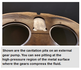
Material failure. The sudden destructive forces of the collapsing bubbles are powerful enough to cause pitting on the pump body or gear. Cavitation pitting has a distinctly different appearance than corrosion or erosion.
Many methods have been used to combat cavitation. In large centrifugal pumps or valves, admitting air into the inlet provides a cushion for the collapsing bubbles and also reduces the noise and pitting caused by cavitation.
Installing an accumulator (a mechanical device that stores the energy of fluid under pressure) close to the inlet port of a piston pump will reduce the effective inlet tubing length, pressurize the inlet, and absorb excess energy (see Fig. 2).
Pitting can be reduced by changing the hardness of the pumping element material or by applying a protective coating; however, these are not long-term solutions to the problem because pitting will attack areas with nicks, scratches, flaws, or sharp corners.
To reduce the undesirable characteristics of cavitation requires an understanding of the interrelationships of system, pump, and liquid. The following techniques have been used to reduce cavitation, but success is dependent upon the application:
Provide adequate pressure to the inlet of the pump, especially in applications with warm or hot liquids, thick viscous fluids, evacuated systems, or when the pumped liquid is volatile. Inlet pressures can be increased by raising the reservoir, lowering the pump, reducing the friction losses of the inlet tubing, or cooling the liquid.
Solutions to cavitation problems are not simple. System changes in gear pump applications can be expensive, time consuming, or both. In the early stages of a project, the design team, consisting of the user and the pump designer, must combine their knowledge to reduce the likelihood of cavitation within a fluid system.
Cavitation is defined as the process of formation and disappearance of the vapor phase of a liquid when it is subjected to reduced and subsequently increased pressures at constant ambient temperatures. The formation of cavities is a process analogous to boiling in a liquid, although it is the result of pressure reduction rather than heat addition. Nonetheless, the basic physical and thermodynamic processes are the same in both cases. The entire process of cavitation is governed by fluid inertia (fluid dynamics) and heat and mass transfer (thermodynamics).
Clearly, from an engineering and design perspective there are two basic questions regarding cavitation. First, one has to answer the question whether cavitation will occur or not, and second, if cavitation is unavoidable, the question is whether a given design can still function properly. Economic or other operational considerations often necessitate operation with some cavitation, and under these circumstances it is particularly important to understand the (deleterious) effects of cavitation.
The potential for cavitation when dealing with pumps is typically evaluated by a parameter called Net Positive Suction Head (NPSH). This is defined as the total head of the fluid at pump suction (HS,T) above the vapor pressure of the fluid (in terms of head, HV): NPSH = HS,T – HV. It can be seen as a measure expressing the margin against vaporization of the fluid entering the pump.
Using a parameter like NPSH one can define various critical values corresponding to certain stages of cavitation or cavitation phenomena. Typically, this includes – but is not limited to – cavitation inception, head drop inception, percentage head drop, and performance breakdown.
The first appearance of cavitation when gradually lowering pump suction pressure from a level high enough to suppress cavitation is called cavitation inception. When pump suction pressure – or NPSH – is decreased further from this inception level, the region of cavitation enlarges, eventually starting to cause fluid-born noise (audible and/or non-audible), performance change (head loss), and finally full head breakdown.
By the time the inlet pressure is lowered enough to cause a certain percentage drop in pump head, cavitation is always fully established. Before reaching that stage there is already a significant amount of cavitation without the pump head being affected by it. This is illustrated by Figure 1, which shows so-called head drop curves. In a curve like this pump head is plotted against NPSH for constant fl ow rate (Q) and constant speed (N). For multi stage pumps one would plot the head of the suction stage.
NPSH required (NPSHR) constitutes the condition of having a specific amount of cavitation being developed inside the pump, or a specific cavitation criterion being established. This implies that a statement on NPSHR is meaningless without specifying the associated condition. NPSHR for a particular condition is a function of volumetric flow rate and speed of the pump.
Historically, the condition of three percent head drop is taken as the NPSHR for (rotodynamic) pumps. Unfortunately, this has led to a lot of misconception since many interpret NPSHR as the one needed to run free from cavitation, while in reality it constitutes the NPSH needed to have the pump cavitating to such an extent that it loses three percent of its head. Current practice of using NPSH3 remedies this misconception.
Other typical and popular NPSHR criteria include: NPSHi for cavitation inception, NPSH0 for the starting of head drop and NPSH1 for one percent head drop. NPSH0 is sometimes termed “incipient NPSH”, which should not be confused with NPSHi.
NPSH should always be reference against a datum plane (elevation). Typical NPSH datum planes include: i) horizontal plane thru impeller (shaft) centerline; ii) top of foundation; iii) impeller eye for vertical pumps or horizontal plane thru suction flange centerline for vertical can pumps. When changing from one NPSH datum plane to another the NPSH needs to be corrected for the static height and any head loss between the two datum planes (Figure 2).
Figure 3 shows typical NPSH characteristics that can be identified for centrifugal and axial-flow pumps. In this figure NPSHA is the NPSH available as provided by the system. Beyond the so-called shockless-entry capacity—or best cavitation point (BCP)—the NPSH3 is seen to follow the steep rise of the inception curve (NPSHi). Below QBCP the inception curve shows an absolutely striking departure from the shape of the conventional NPSH3 curve. Instead of decreasing with decreasing capacity, it rises until a local maximum is reached. This local maximum is of particular importance since it identifies the onset of suction recirculation. It can further be seen that a cavitation free region of operation will exist for those capacities where NPSHA > NPSHi. Outside this region the pump will cavitate and the extent of cavitation will depend on the operating capacity of the pump.
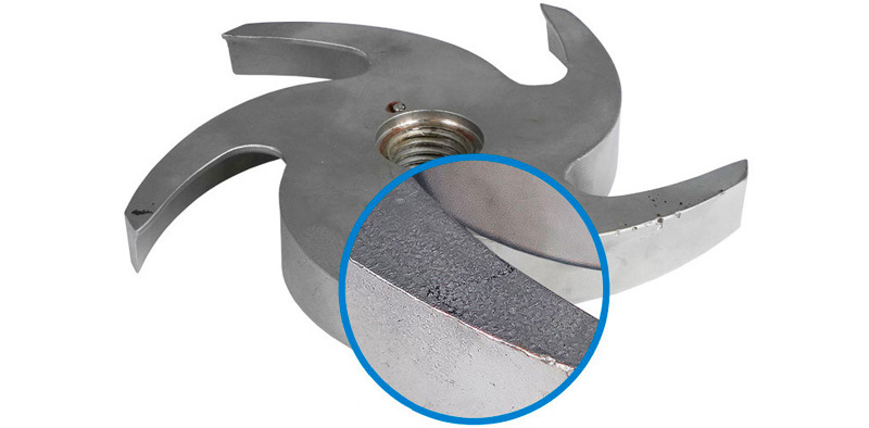
Figure 4 shows an example of an impeller with cavitation damage. Cavitation damage starts somewhere beyond inception and will disappear near head break-off , with maximum erosion rate occurring somewhere in between, and often marginally before NPSH3 (Figure 5). A more accurate description is difficult to give since many parameters influence bubble geometry and its potential for causing damage. For instance, impeller material, air content, NPSH available, vane geometry, inlet geometry, type of cavity, fluid density, and fluid temperature, to name a few, can be contributors or inhibitors of cavitation damage. Furthermore, with maximum erosion rate occurring marginally before NPSH3 one need to be cautious about specifying the NPSH margin (i.e., NPSHA-NPSH3). Without given it proper thought, the NPSH margins suggested in literature may result in running the pump exactly near maximum erosion rate, if cavitation erosion actually occurs.
In order to have cavitation erosion the cavitation vapor pockets need to implode on or near a material surface, and the energy release must exceed the cavitation resistance of the surface material. Since the latter is hard to quantify many experimental and semi-empirical studies have attempted to correlate between cavity shape and damage potential, and research in this field is still ongoing. The only certainty is that the absence of visible cavities means that cavitation damage will not be an issue. This fact is used in some conservative designs, such as liquid sodium pumps, and some water injection applications, where the NPSH available is high enough to suppress cavitation. The occurrence of cavitation erosion is also less of a worry when pumping hydrocarbon mixtures due to the absence of a vapor pressure. The vapor-liquid region of such mixtures, enclosed by the bubble and dew pressure, prevents any violent (high energy) cavity implosions.
Suction specific speed (S or NSS) is often seen as the key indicator determining the susceptibility to cavitation. This, however, causes a lot of misunderstanding and misinterpretation of the concept of suction specific speed. To understand this, one most realize that it is a quantity that originates from scaling model pumps and prototypes, and that is has a clear definition: suction specific speed is the running speed (RPM) of a geometrically identical impeller/pump scaled at a (suction) specific diameter, such that it will have an NPSH of 1 m [1 ft] at a flow rate of 1 m3/h [1 USGPM]; as such (by similarity) the well-known equation to calculate suction specific speed is readily found: NSS = N Q1/2 / NPSH3/4.
Depending on the set of units used this will produce a particular number. Factoring in the acceleration due to gravity (g) and using a consistent set of units yields the universal (dimensionless) number: S = N Q1/2 / gNPSH3/4.
Suction specific speed is a relative index number that should be used and judged with extreme caution. In order to have some consistency the widespread rule is that it should be evaluated at pump peak efficiency capacity, with maximum diameter impeller fitted in the pump. Although this leads to a workable definition in practice, it has some serious drawbacks: i) The volute or diff user characteristic will greatly determine the peak efficiency capacity of the pump, and ii) for multi stage pumps the series stages may have a peak efficiency capacity quite different from the first stage. This makes S or NSS very sensitive to the construction of the entire pump whereas it should only reflect the suction capabilities. A way to overcome this objection is to evaluate S or NSS at the so-called shockless entry capacity of the (suction) impeller.
Lastly, it is paramount to understand that suction specific speed is not an indicator to warrant healthy pump selection or operation in relation to NPSH. Unlike common belief it is not a limiter. At best it can be a caution sign if it is outside the ballpark.
Frank Visser is Principal Engineer at Flowserve, Global Engineering Services, in Etten-Leur, The Netherlands. He joined Flowserve in 1995 and has held several positions in research, development, and (product) engineering. His key expertise and interests relate to fluid mechanics, CFD and thermodynamics of (centrifugal) pumps and hydraulic turbines. He has authored & co-authored multiple technical papers in journals and proceedings, and lectured at various symposia. He has a BS and MS in Mechanical Engineering, and a PhD in Technical Sciences. He has received the ASME 2017 Sankaraiyer Gopalakrishnan-Flowserve Pump Technology Award, is a member of the Industrial Advisory Board for the J.M. Burgers-centrum (JMBC), National Research School for Fluid Mechanics in the Netherlands, and a former Associate Editor for ASME Journal of Fluids Engineering.

This website is using a security service to protect itself from online attacks. The action you just performed triggered the security solution. There are several actions that could trigger this block including submitting a certain word or phrase, a SQL command or malformed data.

Cavitation is a phenomenon in which the static pressure of a liquid reduces to below the liquid"s vapour pressure, leading to the formation of small vapor-filled cavities in the liquid. When subjected to higher pressure, these cavities, called "bubbles" or "voids", collapse and can generate shock waves that may damage machinery. These shock waves are strong when they are very close to the imploded bubble, but rapidly weaken as they propagate away from the implosion. Cavitation is a significant cause of wear in some engineering contexts. Collapsing voids that implode near to a metal surface cause cyclic stress through repeated implosion. This results in surface fatigue of the metal causing a type of wear also called "cavitation". The most common examples of this kind of wear are to pump impellers, and bends where a sudden change in the direction of liquid occurs. Cavitation is usually divided into two classes of behavior: inertial (or transient) cavitation and non-inertial cavitation.
The process in which a void or bubble in a liquid rapidly collapses, producing a shock wave, is called inertial cavitation. Inertial cavitation occurs in nature in the strikes of mantis shrimps and pistol shrimps, as well as in the vascular tissues of plants. In artificial objects, it can occur in control valves, pumps, propellers and impellers.
Non-inertial cavitation is the process in which a bubble in a fluid is forced to oscillate in size or shape due to some form of energy input, such as an acoustic field. Such cavitation is often employed in ultrasonic cleaning baths and can also be observed in pumps, propellers, etc.
Since the shock waves formed by collapse of the voids are strong enough to cause significant damage to parts, cavitation is typically an undesirable phenomenon in machinery (although desirable if intentionally used, for example, to sterilize contaminated surgical instruments, break down pollutants in water purification systems, emulsify tissue for cataract surgery or kidney stone lithotripsy, or homogenize fluids). It is very often specifically prevented in the design of machines such as turbines or propellers, and eliminating cavitation is a major field in the study of fluid dynamics. However, it is sometimes useful and does not cause damage when the bubbles collapse away from machinery, such as in supercavitation.
Inertial cavitation was first observed in the late 19th century, considering the collapse of a spherical void within a liquid. When a volume of liquid is subjected to a sufficiently low pressure, it may rupture and form a cavity. This phenomenon is coined cavitation inception and may occur behind the blade of a rapidly rotating propeller or on any surface vibrating in the liquid with sufficient amplitude and acceleration. A fast-flowing river can cause cavitation on rock surfaces, particularly when there is a drop-off, such as on a waterfall.
Other ways of generating cavitation voids involve the local deposition of energy, such as an intense focused laser pulse (optic cavitation) or with an electrical discharge through a spark. Vapor gases evaporate into the cavity from the surrounding medium; thus, the cavity is not a vacuum at all, but rather a low-pressure vapor (gas) bubble. Once the conditions which caused the bubble to form are no longer present, such as when the bubble moves downstream, the surrounding liquid begins to implode due its higher pressure, building up inertia as it moves inward. As the bubble finally collapses, the inward inertia of the surrounding liquid causes a sharp increase of pressure and temperature of the vapor within. The bubble eventually collapses to a minute fraction of its original size, at which point the gas within dissipates into the surrounding liquid via a rather violent mechanism which releases a significant amount of energy in the form of an acoustic shock wave and as visible light. At the point of total collapse, the temperature of the vapor within the bubble may be several thousand kelvin, and the pressure several hundred atmospheres.
Inertial cavitation can also occur in the presence of an acoustic field. Microscopic gas bubbles that are generally present in a liquid will be forced to oscillate due to an applied acoustic field. If the acoustic intensity is sufficiently high, the bubbles will first grow in size and then rapidly collapse. Hence, inertial cavitation can occur even if the rarefaction in the liquid is insufficient for a Rayleigh-like void to occur. High-power ultrasonics usually utilize the inertial cavitation of microscopic vacuum bubbles for treatment of surfaces, liquids, and slurries.
The physical process of cavitation inception is similar to boiling. The major difference between the two is the thermodynamic paths that precede the formation of the vapor. Boiling occurs when the local temperature of the liquid reaches the saturation temperature, and further heat is supplied to allow the liquid to sufficiently phase change into a gas. Cavitation inception occurs when the local pressure falls sufficiently far below the saturated vapor pressure, a value given by the tensile strength of the liquid at a certain temperature.
In order for cavitation inception to occur, the cavitation "bubbles" generally need a surface on which they can nucleate. This surface can be provided by the sides of a container, by impurities in the liquid, or by small undissolved microbubbles within the liquid. It is generally accepted that hydrophobic surfaces stabilize small bubbles. These pre-existing bubbles start to grow unbounded when they are exposed to a pressure below the threshold pressure, termed Blake"s threshold.
The vapor pressure here differs from the meteorological definition of vapor pressure, which describes the partial pressure of water in the atmosphere at some value less than 100% saturation. Vapor pressure as relating to cavitation refers to the vapor pressure in equilibrium conditions and can therefore be more accurately defined as the equilibrium (or saturated) vapor pressure.
Non-inertial cavitation is the process in which small bubbles in a liquid are forced to oscillate in the presence of an acoustic field, when the intensity of the acoustic field is insufficient to cause total bubble collapse. This form of cavitation causes significantly less erosion than inertial cavitation, and is often used for the cleaning of delicate materials, such as silicon wafers.
Hydrodynamic cavitation is the process of vaporisation, bubble generation and bubble implosion which occurs in a flowing liquid as a result of a decrease and subsequent increase in local pressure. Cavitation will only occur if the local pressure declines to some point below the saturated vapor pressure of the liquid and subsequent recovery above the vapor pressure. If the recovery pressure is not above the vapor pressure then flashing is said to have occurred. In pipe systems, cavitation typically occurs either as the result of an increase in the kinetic energy (through an area constriction) or an increase in the pipe elevation.
Hydrodynamic cavitation can be produced by passing a liquid through a constricted channel at a specific flow velocity or by mechanical rotation of an object through a liquid. In the case of the constricted channel and based on the specific (or unique) geometry of the system, the combination of pressure and kinetic energy can create the hydrodynamic cavitation cavern downstream of the local constriction generating high energy cavitation bubbles.
Based on the thermodynamic phase change diagram, an increase in temperature could initiate a known phase change mechanism known as boiling. However, a decrease in static pressure could also help one pass the multi-phase diagram and initiate another phase change mechanism known as cavitation. On the other hand, a local increase in flow velocity could lead to a static pressure drop to the critical point at which cavitation could be initiated (based on Bernoulli"s principle). The critical pressure point is vapor saturated pressure. In a closed fluidic system where no flow leakage is detected, a decrease in cross-sectional area would lead to velocity increment and hence static pressure drop. This is the working principle of many hydrodynamic cavitation based reactors for different applications such as water treatment, energy harvesting, heat transfer enhancement, food processing, etc.
There are different flow patterns detected as a cavitation flow progresses: inception, developed flow, supercavitation, and choked flow. Inception is the first moment that the second phase (gas phase) appears in the system. This is the weakest cavitating flow captured in a system corresponding to the highest cavitation number. When the cavities grow and becomes larger in size in the orifice or venturi structures, developed flow is recorded. The most intense cavitating flow is known as supercavitation where theoretically all the nozzle area of an orifice is filled with gas bubbles. This flow regime corresponds to the lowest cavitation number in a system. After supercavitation, the system is not capable of passing more flow. Hence, velocity does not change while the upstream pressure increase. This would lead to an increase in cavitation number which shows that choked flow occurred.
The process of bubble generation, and the subsequent growth and collapse of the cavitation bubbles, results in very high energy densities and in very high local temperatures and local pressures at the surface of the bubbles for a very short time. The overall liquid medium environment, therefore, remains at ambient conditions. When uncontrolled, cavitation is damaging; by controlling the flow of the cavitation, however, the power can be harnessed and non-destructive. Controlled cavitation can be used to enhance chemical reactions or propagate certain unexpected reactions because free radicals are generated in the process due to disassociation of vapors trapped in the cavitating bubbles.
Orifices and venturi are reported to be widely used for generating cavitation. A venturi has an inherent advantage over an orifice because of its smooth converging and diverging sections, such that it can generate a higher flow velocity at the throat for a given pressure drop across it. On the other hand, an orifice has an advantage that it can accommodate a greater number of holes (larger perimeter of holes) in a given cross sectional area of the pipe.
The cavitation phenomenon can be controlled to enhance the performance of high-speed marine vessels and projectiles, as well as in material processing technologies, in medicine, etc. Controlling the cavitating flows in liquids can be achieved only by advancing the mathematical foundation of the cavitation processes. These processes are manifested in different ways, the most common ones and promising for control being bubble cavitation and supercavitation. The first exact classical solution should perhaps be credited to the well-known solution by Hermann von Helmholtz in 1868.Jets, wakes and cavitiesTheory of jets of ideal fluid.Hydrodynamics of Flows with Free BoundariesDimensionality and similarity methods in the problems of the hydromechanics of vessels.
Hydrodynamic cavitation can also improve some industrial processes. For instance, cavitated corn slurry shows higher yields in ethanol production compared to uncavitated corn slurry in dry milling facilities.
This is also used in the mineralization of bio-refractory compounds which otherwise would need extremely high temperature and pressure conditions since free radicals are generated in the process due to the dissociation of vapors trapped in the cavitating bubbles, which results in either the intensification of the chemical reaction or may even result in the propagation of certain reactions not possible under otherwise ambient conditions.
In industry, cavitation is often used to homogenize, or mix and break down, suspended particles in a colloidal liquid compound such as paint mixtures or milk. Many industrial mixing machines are based upon this design principle. It is usually achieved through impeller design or by forcing the mixture through an annular opening that has a narrow entrance orifice with a much larger exit orifice. In the latter case, the drastic decrease in pressure as the liquid accelerates into a larger volume induces cavitation. This method can be controlled with hydraulic devices that control inlet orifice size, allowing for dynamic adjustment during the process, or modification for different substances. The surface of this type of mixing valve, against which surface the cavitation bubbles are driven causing their implosion, undergoes tremendous mechanical and thermal localized stress; they are therefore often constructed of extremely strong and hard materials such as stainless steel, Stellite, or even polycrystalline diamond (PCD).
Cavitating water purification devices have also been designed, in which the extreme conditions of cavitation can break down pollutants and organic molecules. Spectral analysis of light emitted in sonochemical reactions reveal chemical and plasma-based mechanisms of energy transfer. The light emitted from cavitation bubbles is termed sonoluminescence.
Hydrophobic chemicals are attracted underwater by cavitation as the pressure difference between the bubbles and the liquid water forces them to join. This effect may assist in protein folding.
Cavitation plays an important role for the destruction of kidney stones in shock wave lithotripsy.cells (sonoporation). Nitrogen cavitation is a method used in research to lyse cell membranes while leaving organelles intact.
Cavitation plays a key role in non-thermal, non-invasive fractionation of tissue for treatment of a variety of diseasesblood-brain barrier to increase uptake of neurological drugs in the brain.
In wounds caused by high velocity impacts (like for example bullet wounds) there are also effects due to cavitation. The exact wounding mechanisms are not completely understood yet as there is temporary cavitation, and permanent cavitation together with crushing, tearing and stretching. Also the high variance in density within the body makes it hard to determine its effects.
In industrial cleaning applications, cavitation has sufficient power to overcome the particle-to-substrate adhesion forces, loosening contaminants. The threshold pressure required to initiate cavitation is a strong function of the pulse width and the power input. This method works by generating acoustic cavitation in the cleaning fluid, picking up and carrying contaminant particles away in the hope that they do not reattach to the material being cleaned (which is a possibility when the object is immersed, for example in an ultrasonic cleaning bath). The same physical forces that remove contaminants also have the potential to damage the target being cleaned.
Cavitation has been applied to egg pasteurization. A hole-filled rotor produces cavitation bubbles, heating the liquid from within. Equipment surfaces stay cooler than the passing liquid, so eggs don"t harden as they did on the hot surfaces of older equipment. The intensity of cavitation can be adjusted, making it possible to tune the process for minimum protein damage.
Cavitation has been applied to vegetable oil degumming and refining since 2011 and is considered a proven and standard technology in this application. The implementation of hydrodynamic cavitation in the degumming and refining process allows for a significant reduction in process aid, such as chemicals, water and bleaching clay, use.
Cavitation has been applied to Biodiesel production since 2011 and is considered a proven and standard technology in this application. The implementation of hydrodynamic cavitation in the transesterification process allows for a significant reduction in catalyst use, quality improvement and production capacity increase.
Cavitation is, in many cases, an undesirable occurrence. In devices such as propellers and pumps, cavitation causes a great deal of noise, damage to components, vibrations, and a loss of efficiency. Noise caused by cavitation can be particularly undesirable in naval vessels where such noise may render them more easily detectable by passive sonar. Cavitation has also become a concern in the renewable energy sector as it may occur on the blade surface of tidal stream turbines.
When the cavitation bubbles collapse, they force energetic liquid into very small volumes, thereby creating spots of high temperature and emitting shock waves, the latter of which are a source of noise. The noise created by cavitation is a particular problem for military submarines, as it increases the chances of being detected by passive sonar.
After a surface is initially affected by cavitation, it tends to erode at an accelerating pace. The cavitation pits increase the turbulence of the fluid flow and create crevices that act as nucleation sites for additional cavitation bubbles. The pits also increase the components" surface area and leave behind residual stresses. This makes the surface more prone to stress corrosion.
As an impeller"s (in a pump) or propeller"s (as in the case of a ship or submarine) blades move through a fluid, low-pressure areas are formed as the fluid accelerates around and moves past the blades. The faster the blade moves, the lower the pressure can become around it. As it reaches vapor pressure, the fluid vaporizes and forms small bubbles of gas. This is cavitation. When the bubbles collapse later, they typically cause very strong local shock waves in the fluid, which may be audible and may even damage the blades.
Suction cavitation occurs when the pump suction is under a low-pressure/high-vacuum condition where the liquid turns into a vapor at the eye of the pump impeller. This vapor is carried over to the discharge side of the pump, where it no longer sees vacuum and is compressed back into a liquid by the discharge pressure. This imploding action occurs violently and attacks the face of the impeller. An impeller that has been operating under a suction cavitation condition can have large chunks of material removed from its face or very small bits of material removed, causing the impeller to look spongelike. Both cases will cause premature failure of the pump, often due to bearing failure. Suction cavitation is often identified by a sound like gravel or marbles in the pump casing.
Common causes of suction cavitation can include clogged filters, pipe blockage on the suction side, poor piping design, pump running too far right on the pump curve, or conditions not meeting NPSH (net positive suction head) requirements.
In automotive applications, a clogged filter in a hydraulic system (power steering, power brakes) can cause suction cavitation making a noise that rises and falls in synch with engine RPM. It is fairly often a high pitched whine, like set of nylon gears not quite meshing correctly.
Discharge cavitation occurs when the pump discharge pressure is extremely high, normally occurring in a pump that is running at less than 10% of its best efficiency point. The high discharge pressure causes the majority of the fluid to circulate inside the pump instead of being allowed to flow out the discharge. As the liquid flows around the impeller, it must pass through the small clearance between the impeller and the pump housing at extremely high flow velocity. This flow velocity causes a vacuum to develop at the housing wall (similar to what occurs in a venturi), which turns the liquid into a vapor. A pump that has been operating under these conditions shows premature wear of the impeller vane tips and the pump housing. In addition, due to the high pressure conditions, premature failure of the pump"s mechanical seal and bearings can be expected. Under extreme conditions, this can break the impeller shaft.
Discharge cavitation in joint fluid is thought to cause the popping sound produced by bone joint cracking, for example by deliberately cracking one"s knuckles.
Since all pumps require well-developed inlet flow to meet their potential, a pump may not perform or be as reliable as expected due to a faulty suction piping layout such as a close-coupled elbow on the inlet flange. When poorly developed flow enters the pump impeller, it strikes the vanes and is unable to follow the impeller passage. The liquid then separates from the vanes causing mechanical problems due to cavitation, vibration and performance problems due to turbulence and poor filling of the impeller. This results in premature seal, bearing and impeller failure, high maintenance costs, high power consumption, and less-than-specified head and/or flow.
To have a well-developed flow pattern, pump manufacturer"s manuals recommend about (10 diameters?) of straight pipe run upstream of the pump inlet flange. Unfortunately, piping designers and plant personnel must contend with space and equipment layout constraints and usually cannot comply with this recommendation. Instead, it is common to use an elbow close-coupled to the pump suction which creates a poorly developed flow pattern at the pump suction.
With a double-suction pump tied to a close-coupled elbow, flow distribution to the impeller is poor and causes reliability and performance shortfalls. The elbow divides the flow unevenly with more channeled to the outside of the elbow. Consequently, one side of the double-suction impeller receives more flow at a higher flow velocity and pressure while the starved side receives a highly turbulent and potentially damaging flow. This degrades overall pump performance (delivered head, flow and power consumption) and causes axial imbalance which shortens seal, bearing and impeller life.
When water flows over a dam spillway, the irregularities on the spillway surface will cause small areas of flow separation in a high-speed flow, and, in these regions, the pressure will be lowered. If the flow velocities are high enough the pressure may fall to below the local vapor pressure of the water and vapor bubbles will form. When these are carried downstream into a high pressure region the bubbles collapse giving rise to high pressures and possible cavitation damage.
Experimental investigations show that the damage on concrete chute and tunnel spillways can start at clear water flow velocities of between 12 and 15 m/s (27 and 34 mph), and, up to flow velocities of 20 m/s (45 mph), it may be possible to protect the surface by streamlining the boundaries, improving the surface finishes or using resistant materials.
The spillway aeration device design is based upon a small deflection of the spillway bed (or sidewall) such as a ramp and offset to deflect the high flow velocity flow away from the spillway surface. In the cavity formed below the nappe, a local subpressure beneath the nappe is produced by which air is sucked into the flow. The complete design includes the deflection device (ramp, offset) and the air supply system.
Some larger diesel engines suffer from cavitation due to high compression and undersized cylinder walls. Vibrations of the cylinder wall induce alternating low and high pressure in the coolant against the cylinder wall. The result is pitting of the cylinder wall, which will eventually let cooling fluid leak into the cylinder and combustion gases to leak into the coolant.
It is possible to prevent this from happening with the use of chemical additives in the cooling fluid that form a protective layer on the cylinder wall. This layer will be exposed to the same cavitation, but rebuilds itself. Additionally a regulated overpressure in the cooling system (regulated and maintained by the coolant filler cap spring pressure) prevents the forming of cavitation.
From about the 1980s, new designs of smaller gasoline engines also displayed cavitation phenomena. One answer to the need for smaller and lighter engines was a smaller coolant volume and a correspondingly higher coolant flow velocity. This gave rise to rapid changes in flow velocity and therefore rapid changes of static pressure in areas of high heat transfer. Where resulting vapor bubbles collapsed against a surface, they had the effect of first disrupting protective oxide layers (of cast aluminium materials) and then repeatedly damaging the newly formed surface, preventing the action of some types of corrosion inhibitor (such as silicate based inhibitors). A final problem was the effect that increased material temperature had on the relative electrochemical reactivity of the base metal and its alloying constituents. The result was deep pits that could form and penetrate the engine head in a matter of hours when the engine was running at high load and high speed. These effects could largely be avoided by the use of organic corrosion inhibitors or (preferably) by designing the engine head in such a way as to avoid certain cavitation inducing conditions.
Some hypothesesdiamond formation posit a possible role for cavitation—namely cavitation in the kimberlite pipes providing the extreme pressure needed to change pure carbon into the rare allotrope that is diamond. The loudest three sounds ever recorded, during the 1883 eruption of Krakatoa, are now
Cavitation can occur in the xylem of vascular plants.sap vaporizes locally so that either the vessel elements or tracheids are filled with water vapor. Plants are able to repair cavitated xylem in a number of ways. For plants less than 50 cm tall, root pressure can be sufficient to redissolve the vapor. Larger plants direct solutes into the xylem via ray cells, or in tracheids, via osmosis through bordered pits. Solutes attract water, the pressure rises and vapor can redissolve. In some trees, the sound of the cavitation is audible, particularly in summer, when the rate of evapotranspiration is highest. Some deciduous trees have to shed leaves in the autumn partly because cavitation increases as temperatures decrease.
Cavitation plays a role in the spore dispersal mechanisms of cer


 8613371530291