
what size hydraulic pump do i need quotation

Sudenga Industries is a leading manufacturer of durable ag equipment for grain, feed and seed handling applications. Products can be found in farm and commercial agriculture installations as well as industrial material handling applications worldwide. Sudenga was founded in 1888 in the northwest corner of Iowa where it is still located today.
Knowing how to right-size an electric motor for your hydraulic pump can help reduce energy consumption and increase operational efficiency. The key is to ensure the pump motor is operating at peak continuous load. But how can you know how much power is needed?
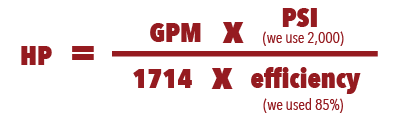
Before you can choose the correct electric motor, you must know how much horsepower (Hp) is required to drive the pump shaft. Generally, this is calculated by multiplying the flow capacity in gallons per minute (GPM) by the pressure in pounds per square inch (PSI). You then divide the resulting number by 1714 times the efficiency of the pump, for a formula that looks like this:
If you’re not sure how efficient your hydraulic pump is, it is advisable to use a common efficiency of about 85% (Multiplying 1714 x 0.85 = 1460 or 1500 if you round up). This work-around simplifies the formula to:
The above formula works in most applications with one notable exception: If the operating pressure of a pump is very low, the overall efficiency will be much lower than 85%. That’s because overall efficiency is equal to mechanical efficiency (internal mechanical friction) plus volumetric efficiency.
Internal friction is generally a fixed value, but volumetric efficiency changes depending on the pressure used. Low-pressure pumps have high volumetric efficiency because they are less susceptible to internal leakage. However, as the pressure goes up and internal fluids pass over work surfaces such as pistons, port plates, and lubrication points, the volumetric efficiency goes down and the amount of torque required to turn the pump for developing pressure goes up.
This variance makes it very important to know the efficiency of your pump if you’re using it at low pressure! Calculations that do not take low pressure into account will lead to a failed design.
If you calculate 20 GPM @ 300 PSI with an assumed overall efficiency of 89%, you would probably select a 5 Hp electric motor. However, if you calculate the same 20 GPM @ 300 PSI with the actual overall efficiency of 50%, you would know that you should be using a 7.5 Hp motor. In this example, making an assumption about the efficiency of your pump could result in installing a motor that is too large, driving up your overall operating cost.
There are many contributors to the overall efficiency of a hydraulic pump, and it pays to be as accurate as possible when choosing a motor. A best practice for proper sizing is to use published data from the pump vendor that shows actual input torque vs. pressure or overall efficiency vs pressure. Note that efficiency is also affected by RPM.
Identifying a right-sized motor for your hydraulic pump does not always ensure you are using the most efficient motor. Be sure to read Part 2 of this post to learn how RMS loading and Hp limiting can help you scale down the size of your electric motor to save money while maximizing efficiency.

This website is using a security service to protect itself from online attacks. The action you just performed triggered the security solution. There are several actions that could trigger this block including submitting a certain word or phrase, a SQL command or malformed data.

Calculation of preliminary cooler capacity: Heat dissipation from hydraulic oil tanks, valves, pipes and hydraulic components is less than a few percent in standard mobile equipment and the cooler capacity must include some margins. Minimum cooler capacity, Ecooler = 0.25Ediesel
At least 25% of the input power must be dissipated by the cooler when peak power is utilized for long periods. In normal case however, the peak power is used for only short periods, thus the actual cooler capacity required might be considerably less. The oil volume in the hydraulic tank is also acting as a heat accumulator when peak power is used.
The system efficiency is very much dependent on the type of hydraulic work tool equipment, the hydraulic pumps and motors used and power input to the hydraulics may vary considerably. Each circuit must be evaluated and the load cycle estimated. New or modified systems must always be tested in practical work, covering all possible load cycles.
An easy way of measuring the actual average power loss in the system is to equip the machine with a test cooler and measure the oil temperature at the cooler inlet, the oil temperature at the cooler outlet and the oil flow through the cooler, when the machine is in normal operating mode. From these figures the test cooler power dissipation can be calculated and this is equal to the power loss when temperatures are stabilized. From this test the actual required cooler can be calculated to reach specified oil temperature in the oil tank. One problem can be to assemble the measuring equipment in-line, especially the oil flow meter.

Selecting the proper line size for a hydraulic system is critical to get maximum performance and life from your hydraulic components. The four basic line types in a hydraulic system are pump suction, return (Low pressure <100 PSI), medium pressure (500 to 2000 PSI), and high pressure (2100 to 5000 PSI). Under-sizing fluid lines will result in high pressure loss and system overheating. Over sizing lines increases the cost of the system. Lines should be sized as follows:
On extremely long lines the pressure drop through the pressure and return lines must be accounted for to insure sufficient pressure is available at the actuator.
The Following velocity charts are a quick way to check velocity through a line. Included in the charts is the I.D. of the line. If the particular tube, pipe or hose you are using is not listed, reference a line with a similar I.D. for approximate velocity.
Pressure drop through the conductor must be accounted for in long runs of pipe, hose or tubing. This will insure you have sufficient pressure available at your actuator to do work and sufficient horsepower available at the pump. You can use the following charts to estimate total pressure drop through a conductor based on fluid velocity. Included in the charts is the I.D. of the conductor, so if the particular tube or pipe you are using is not listed you can reference a conductor with a similar I.D. for approximate pressure drop.
Fluid viscosity plays a very large part in calculating pressure drop through the system. The charts below are based on ISO grade 46 hydraulic oil with a viscosity of approximately 225 S.S.U. at 100 deg. F and .88 specific gravity. Actual pressure drop will increase as viscosity increases.
By using the information supplied in this tech tip and selecting the proper line sizes for your hydraulic equipment you will enjoy better performance and longer life from your hydraulic components. Flow will be more laminar, shock potential reduced, leak potential greatly lowered, fitting and connector life increased, wear and tear exposure on system components reduced and concern for excessive heat build-up minimized.
Note: “Tech Tips” offered by Flodraulic Group or its companies are presented as a convenience to those who may wish to use them and are not presented as an alternative to formal fluid power education or professional system design assistance.

A hydraulic motor is an apparatus that is used to actuate rotational motion. Its method of operation is not unlike that of hydraulic cylinders, which are used to actuate linear motion. Both kinds of equipment involve the use of pressurized hydraulic fluid, which is directed into the equipment through inlets. The force exerted by the pressurized fluid causes the moving parts of the equipment to move. A hydraulic motor is composed of an outer housing with two inlets and a rotor contained within the housing. When hydraulic fluid is forced into the housing through an inlet, it causes the rotor to turn, which in turn causes any attached equipment to rotate as well. Depending on the size and design of the motor, they can be used to generate fairly small amounts of torque, or they can be large enough to rotate components of heavy machinery.
These motors are utilized in many different applications, such as in manufacturing, construction, agricultural, and many other industries. In the construction industry, hydraulic motors are often integral components of heavy-duty vehicles. For example, in excavators, a hydraulic motor is located at the point where the cab makes contact with the track or wheel platform. The hydraulic motor between the platform and the cab allows the top portion of the vehicle to rotate a full 360 degrees.
An excavator hydraulic motor is not an example of a high speed hydraulic motor. In fact, many of these heavy-duty vehicles require more torque and precision than speed. After all, they’re used to move tremendously heavy materials, and especially in the case of small vehicles, they’re often deployed in situations where false moves could have consequences for nearby utilities like water mains and gas lines. For this reason, some of these hydraulic motors are capable of generating cab rotation without wobbling, and their motion can be carefully and precisely controlled.

Constructed of high strength aluminum housing and cast iron end covers. High performance, high efficiency at low and high speed operation, low noise. Keyway size 3/16’’ 3/4’’ Dia. Straight Keyed Shaft 1 1/4’’ Long.

An electric motor can be overloaded for short periods during the cycle provided the average horsepower is no greater than its nameplate rating plus service factor where this applies.
The amount of intermittent overloading is up to the user, but we suggest the overload be no more than 25% above its nameplate current rating sustained no longer than about 10% of the time required for a complete cycle.
Most A-C 60 Hz motors can be operated on a 50 Hz line and vice versa, but adjustments will have to be made in the current, HP, and speed ratings. The important thing to remember is that it is the current which causes heating. The HP which can be produced will be related to its current draw, and may be more or less than its nameplate rating.
*Voltage adjustment is to maintain current at rated value, to produce rated shaft torque. Current is always a limiting factor on a variation in rated Hz (frequency) or voltage.
Nameplate HP is based on full voltage being available. HP output is a combination of voltage times current. If voltage is too low, then to produce rated HP the current must be too high, and this overheats the motor. Motors can usually accommodate as low as 90% of rated voltage and still produce nameplate HP although temperature rise in the windings will be greater than rated rise. For permanent operation on a voltage source known to be low, the HP load should be limited, and reduced by the same percentage that the voltage is low.
If motor load does not exceed nameplate HP rating, full load current will be lower than nameplate rating and the motor will run cooler than rating. However, its starting and breakdown current (at stall) will be higher than normal. The wiring, fusing, and thermal overload protection will have to be sized accordingly. Motor noise will increase.
Using a 20 HP motor on a system which requires only 10 HP, for example, will give good results for running the pump but will consume more electricity than a 10 HP motor and will cause the power factor of the plant electric system to be poorer, especially during periods the motor is idling. Idling current of a 20 HP motor is about half the full load current of a 10 HP motor. This is an extra power waste during periods in the cycle when the pump is idling.
Using a 20 HP motor on a system which requires 25 HP for brief periods is quite possible, but during overload periods the current of such a motor maybe-about twice the current of a 25 HP motor. There will be an extra waste of power during peak periods in the cycle. But the smaller motor could more than make this up during periods in the cycle when less than 20 HP is required.

Hydraulic pumps are mechanisms in hydraulic systems that move hydraulic fluid from point to point initiating the production of hydraulic power. Hydraulic pumps are sometimes incorrectly referred to as “hydrolic” pumps.
They are an important device overall in the hydraulics field, a special kind of power transmission which controls the energy which moving fluids transmit while under pressure and change into mechanical energy. Other kinds of pumps utilized to transmit hydraulic fluids could also be referred to as hydraulic pumps. There is a wide range of contexts in which hydraulic systems are applied, hence they are very important in many commercial, industrial, and consumer utilities.
“Power transmission” alludes to the complete procedure of technologically changing energy into a beneficial form for practical applications. Mechanical power, electrical power, and fluid power are the three major branches that make up the power transmission field. Fluid power covers the usage of moving gas and moving fluids for the transmission of power. Hydraulics are then considered as a sub category of fluid power that focuses on fluid use in opposition to gas use. The other fluid power field is known as pneumatics and it’s focused on the storage and release of energy with compressed gas.
"Pascal"s Law" applies to confined liquids. Thus, in order for liquids to act hydraulically, they must be contained within a system. A hydraulic power pack or hydraulic power unit is a confined mechanical system that utilizes liquid hydraulically. Despite the fact that specific operating systems vary, all hydraulic power units share the same basic components. A reservoir, valves, a piping/tubing system, a pump, and actuators are examples of these components. Similarly, despite their versatility and adaptability, these mechanisms work together in related operating processes at the heart of all hydraulic power packs.
The hydraulic reservoir"s function is to hold a volume of liquid, transfer heat from the system, permit solid pollutants to settle, and aid in releasing moisture and air from the liquid.
Mechanical energy is changed to hydraulic energy by the hydraulic pump. This is accomplished through the movement of liquid, which serves as the transmission medium. All hydraulic pumps operate on the same basic principle of dispensing fluid volume against a resistive load or pressure.
Hydraulic valves are utilized to start, stop, and direct liquid flow in a system. Hydraulic valves are made of spools or poppets and can be actuated hydraulically, pneumatically, manually, electrically, or mechanically.
The end result of Pascal"s law is hydraulic actuators. This is the point at which hydraulic energy is transformed back to mechanical energy. This can be accomplished by using a hydraulic cylinder to transform hydraulic energy into linear movement and work or a hydraulic motor to transform hydraulic energy into rotational motion and work. Hydraulic motors and hydraulic cylinders, like hydraulic pumps, have various subtypes, each meant for specific design use.
The essence of hydraulics can be found in a fundamental physical fact: fluids are incompressible. (As a result, fluids more closely resemble solids than compressible gasses) The incompressible essence of fluid allows it to transfer force and speed very efficiently. This fact is summed up by a variant of "Pascal"s Principle," which states that virtually all pressure enforced on any part of a fluid is transferred to every other part of the fluid. This scientific principle states, in other words, that pressure applied to a fluid transmits equally in all directions.
Furthermore, the force transferred through a fluid has the ability to multiply as it moves. In a slightly more abstract sense, because fluids are incompressible, pressurized fluids should keep a consistent pressure just as they move. Pressure is defined mathematically as a force acting per particular area unit (P = F/A). A simplified version of this equation shows that force is the product of area and pressure (F = P x A). Thus, by varying the size or area of various parts inside a hydraulic system, the force acting inside the pump can be adjusted accordingly (to either greater or lesser). The need for pressure to remain constant is what causes force and area to mirror each other (on the basis of either shrinking or growing). A hydraulic system with a piston five times larger than a second piston can demonstrate this force-area relationship. When a force (e.g., 50lbs) is exerted on the smaller piston, it is multiplied by five (e.g., 250 lbs) and transmitted to the larger piston via the hydraulic system.
Hydraulics is built on fluids’ chemical properties and the physical relationship between pressure, area, and force. Overall, hydraulic applications allow human operators to generate and exert immense mechanical force with little to no physical effort. Within hydraulic systems, both oil and water are used to transmit power. The use of oil, on the other hand, is far more common, owing in part to its extremely incompressible nature.
Pressure relief valves prevent excess pressure by regulating the actuators’ output and redirecting liquid back to the reservoir when necessary. Directional control valves are used to change the size and direction of hydraulic fluid flow.
While hydraulic power transmission is remarkably useful in a wide range of professional applications, relying solely on one type of power transmission is generally unwise. On the contrary, the most efficient strategy is to combine a wide range of power transmissions (pneumatic, hydraulic, mechanical, and electrical). As a result, hydraulic systems must be carefully embedded into an overall power transmission strategy for the specific commercial application. It is necessary to invest in locating trustworthy and skilled hydraulic manufacturers/suppliers who can aid in the development and implementation of an overall hydraulic strategy.
The intended use of a hydraulic pump must be considered when selecting a specific type. This is significant because some pumps may only perform one function, whereas others allow for greater flexibility.
The pump"s material composition must also be considered in the application context. The cylinders, pistons, and gears are frequently made of long-lasting materials like aluminum, stainless steel, or steel that can withstand the continuous wear of repeated pumping. The materials must be able to withstand not only the process but also the hydraulic fluids. Composite fluids frequently contain oils, polyalkylene glycols, esters, butanol, and corrosion inhibitors (though water is used in some instances). The operating temperature, flash point, and viscosity of these fluids differ.
In addition to material, manufacturers must compare hydraulic pump operating specifications to make sure that intended utilization does not exceed pump abilities. The many variables in hydraulic pump functionality include maximum operating pressure, continuous operating pressure, horsepower, operating speed, power source, pump weight, and maximum fluid flow. Standard measurements like length, rod extension, and diameter should be compared as well. Because hydraulic pumps are used in lifts, cranes, motors, and other heavy machinery, they must meet strict operating specifications.
It is critical to recall that the overall power generated by any hydraulic drive system is influenced by various inefficiencies that must be considered in order to get the most out of the system. The presence of air bubbles within a hydraulic drive, for example, is known for changing the direction of the energy flow inside the system (since energy is wasted on the way to the actuators on bubble compression). Using a hydraulic drive system requires identifying shortfalls and selecting the best parts to mitigate their effects. A hydraulic pump is the "generator" side of a hydraulic system that initiates the hydraulic procedure (as opposed to the "actuator" side that completes the hydraulic procedure). Regardless of disparities, all hydraulic pumps are responsible for displacing liquid volume and transporting it to the actuator(s) from the reservoir via the tubing system. Some form of internal combustion system typically powers pumps.
While the operation of hydraulic pumps is normally the same, these mechanisms can be split into basic categories. There are two types of hydraulic pumps to consider: gear pumps and piston pumps. Radial and axial piston pumps are types of piston pumps. Axial pumps produce linear motion, whereas radial pumps can produce rotary motion. The gear pump category is further subdivided into external gear pumps and internal gear pumps.
Each type of hydraulic pump, regardless of piston or gear, is either double-action or single-action. Single-action pumps can only pull, push, or lift in one direction, while double-action pumps can pull, push, or lift in multiple directions.
Vane pumps are positive displacement pumps that maintain a constant flow rate under varying pressures. It is a pump that self-primes. It is referred to as a "vane pump" because the effect of the vane pressurizes the liquid.
This pump has a variable number of vanes mounted onto a rotor that rotates within the cavity. These vanes may be variable in length and tensioned to maintain contact with the wall while the pump draws power. The pump also features a pressure relief valve, which prevents pressure rise inside the pump from damaging it.
Internal gear pumps and external gear pumps are the two main types of hydraulic gear pumps. Pumps with external gears have two spur gears, the spurs of which are all externally arranged. Internal gear pumps also feature two spur gears, and the spurs of both gears are internally arranged, with one gear spinning around inside the other.
Both types of gear pumps deliver a consistent amount of liquid with each spinning of the gears. Hydraulic gear pumps are popular due to their versatility, effectiveness, and fairly simple design. Furthermore, because they are obtainable in a variety of configurations, they can be used in a wide range of consumer, industrial, and commercial product contexts.
Hydraulic ram pumps are cyclic machines that use water power, also referred to as hydropower, to transport water to a higher level than its original source. This hydraulic pump type is powered solely by the momentum of moving or falling water.
Ram pumps are a common type of hydraulic pump, especially among other types of hydraulic water pumps. Hydraulic ram pumps are utilized to move the water in the waste management, agricultural, sewage, plumbing, manufacturing, and engineering industries, though only about ten percent of the water utilized to run the pump gets to the planned end point.
Despite this disadvantage, using hydropower instead of an external energy source to power this kind of pump makes it a prominent choice in developing countries where the availability of the fuel and electricity required to energize motorized pumps is limited. The use of hydropower also reduces energy consumption for industrial factories and plants significantly. Having only two moving parts is another advantage of the hydraulic ram, making installation fairly simple in areas with free falling or flowing water. The water amount and the rate at which it falls have an important effect on the pump"s success. It is critical to keep this in mind when choosing a location for a pump and a water source. Length, size, diameter, minimum and maximum flow rates, and speed of operation are all important factors to consider.
Hydraulic water pumps are machines that move water from one location to another. Because water pumps are used in so many different applications, there are numerous hydraulic water pump variations.
Water pumps are useful in a variety of situations. Hydraulic pumps can be used to direct water where it is needed in industry, where water is often an ingredient in an industrial process or product. Water pumps are essential in supplying water to people in homes, particularly in rural residences that are not linked to a large sewage circuit. Water pumps are required in commercial settings to transport water to the upper floors of high rise buildings. Hydraulic water pumps in all of these situations could be powered by fuel, electricity, or even by hand, as is the situation with hydraulic hand pumps.
Water pumps in developed economies are typically automated and powered by electricity. Alternative pumping tools are frequently used in developing economies where dependable and cost effective sources of electricity and fuel are scarce. Hydraulic ram pumps, for example, can deliver water to remote locations without the use of electricity or fuel. These pumps rely solely on a moving stream of water’s force and a properly configured number of valves, tubes, and compression chambers.
Electric hydraulic pumps are hydraulic liquid transmission machines that use electricity to operate. They are frequently used to transfer hydraulic liquid from a reservoir to an actuator, like a hydraulic cylinder. These actuation mechanisms are an essential component of a wide range of hydraulic machinery.
There are several different types of hydraulic pumps, but the defining feature of each type is the use of pressurized fluids to accomplish a job. The natural characteristics of water, for example, are harnessed in the particular instance of hydraulic water pumps to transport water from one location to another. Hydraulic gear pumps and hydraulic piston pumps work in the same way to help actuate the motion of a piston in a mechanical system.
Despite the fact that there are numerous varieties of each of these pump mechanisms, all of them are powered by electricity. In such instances, an electric current flows through the motor, which turns impellers or other devices inside the pump system to create pressure differences; these differential pressure levels enable fluids to flow through the pump. Pump systems of this type can be utilized to direct hydraulic liquid to industrial machines such as commercial equipment like elevators or excavators.
Hydraulic hand pumps are fluid transmission machines that utilize the mechanical force generated by a manually operated actuator. A manually operated actuator could be a lever, a toggle, a handle, or any of a variety of other parts. Hydraulic hand pumps are utilized for hydraulic fluid distribution, water pumping, and various other applications.
Hydraulic hand pumps may be utilized for a variety of tasks, including hydraulic liquid direction to circuits in helicopters and other aircraft, instrument calibration, and piston actuation in hydraulic cylinders. Hydraulic hand pumps of this type use manual power to put hydraulic fluids under pressure. They can be utilized to test the pressure in a variety of devices such as hoses, pipes, valves, sprinklers, and heat exchangers systems. Hand pumps are extraordinarily simple to use.
Each hydraulic hand pump has a lever or other actuation handle linked to the pump that, when pulled and pushed, causes the hydraulic liquid in the pump"s system to be depressurized or pressurized. This action, in the instance of a hydraulic machine, provides power to the devices to which the pump is attached. The actuation of a water pump causes the liquid to be pulled from its source and transferred to another location. Hydraulic hand pumps will remain relevant as long as hydraulics are used in the commerce industry, owing to their simplicity and easy usage.
12V hydraulic pumps are hydraulic power devices that operate on 12 volts DC supplied by a battery or motor. These are specially designed processes that, like all hydraulic pumps, are applied in commercial, industrial, and consumer places to convert kinetic energy into beneficial mechanical energy through pressurized viscous liquids. This converted energy is put to use in a variety of industries.
Hydraulic pumps are commonly used to pull, push, and lift heavy loads in motorized and vehicle machines. Hydraulic water pumps may also be powered by 12V batteries and are used to move water out of or into the desired location. These electric hydraulic pumps are common since they run on small batteries, allowing for ease of portability. Such portability is sometimes required in waste removal systems and vehiclies. In addition to portable and compact models, options include variable amp hour productions, rechargeable battery pumps, and variable weights.
While non rechargeable alkaline 12V hydraulic pumps are used, rechargeable ones are much more common because they enable a continuous flow. More considerations include minimum discharge flow, maximum discharge pressure, discharge size, and inlet size. As 12V batteries are able to pump up to 150 feet from the ground, it is imperative to choose the right pump for a given use.
Air hydraulic pumps are hydraulic power devices that use compressed air to stimulate a pump mechanism, generating useful energy from a pressurized liquid. These devices are also known as pneumatic hydraulic pumps and are applied in a variety of industries to assist in the lifting of heavy loads and transportation of materials with minimal initial force.
Air pumps, like all hydraulic pumps, begin with the same components. The hydraulic liquids, which are typically oil or water-based composites, require the use of a reservoir. The fluid is moved from the storage tank to the hydraulic cylinder via hoses or tubes connected to this reservoir. The hydraulic cylinder houses a piston system and two valves. A hydraulic fluid intake valve allows hydraulic liquid to enter and then traps it by closing. The discharge valve is the point at which the high pressure fluid stream is released. Air hydraulic pumps have a linked air cylinder in addition to the hydraulic cylinder enclosing one end of the piston.
The protruding end of the piston is acted upon by a compressed air compressor or air in the cylinder. When the air cylinder is empty, a spring system in the hydraulic cylinder pushes the piston out. This makes a vacuum, which sucks fluid from the reservoir into the hydraulic cylinder. When the air compressor is under pressure, it engages the piston and pushes it deeper into the hydraulic cylinder and compresses the liquids. This pumping action is repeated until the hydraulic cylinder pressure is high enough to forcibly push fluid out through the discharge check valve. In some instances, this is connected to a nozzle and hoses, with the important part being the pressurized stream. Other uses apply the energy of this stream to pull, lift, and push heavy loads.
Hydraulic piston pumps transfer hydraulic liquids through a cylinder using plunger-like equipment to successfully raise the pressure for a machine, enabling it to pull, lift, and push heavy loads. This type of hydraulic pump is the power source for heavy-duty machines like excavators, backhoes, loaders, diggers, and cranes. Piston pumps are used in a variety of industries, including automotive, aeronautics, power generation, military, marine, and manufacturing, to mention a few.
Hydraulic piston pumps are common due to their capability to enhance energy usage productivity. A hydraulic hand pump energized by a hand or foot pedal can convert a force of 4.5 pounds into a load-moving force of 100 pounds. Electric hydraulic pumps can attain pressure reaching 4,000 PSI. Because capacities vary so much, the desired usage pump must be carefully considered. Several other factors must also be considered. Standard and custom configurations of operating speeds, task-specific power sources, pump weights, and maximum fluid flows are widely available. Measurements such as rod extension length, diameter, width, and height should also be considered, particularly when a hydraulic piston pump is to be installed in place of a current hydraulic piston pump.
Hydraulic clutch pumps are mechanisms that include a clutch assembly and a pump that enables the user to apply the necessary pressure to disengage or engage the clutch mechanism. Hydraulic clutches are crafted to either link two shafts and lock them together to rotate at the same speed or detach the shafts and allow them to rotate at different speeds as needed to decelerate or shift gears.
Hydraulic pumps change hydraulic energy to mechanical energy. Hydraulic pumps are particularly designed machines utilized in commercial, industrial, and residential areas to generate useful energy from different viscous liquids pressurization. Hydraulic pumps are exceptionally simple yet effective machines for moving fluids. "Hydraulic" is actually often misspelled as "Hydralic". Hydraulic pumps depend on the energy provided by hydraulic cylinders to power different machines and mechanisms.
There are several different types of hydraulic pumps, and all hydraulic pumps can be split into two primary categories. The first category includes hydraulic pumps that function without the assistance of auxiliary power sources such as electric motors and gas. These hydraulic pump types can use the kinetic energy of a fluid to transfer it from one location to another. These pumps are commonly called ram pumps. Hydraulic hand pumps are never regarded as ram pumps, despite the fact that their operating principles are similar.
The construction, excavation, automotive manufacturing, agriculture, manufacturing, and defense contracting industries are just a few examples of operations that apply hydraulics power in normal, daily procedures. Since hydraulics usage is so prevalent, hydraulic pumps are unsurprisingly used in a wide range of machines and industries. Pumps serve the same basic function in all contexts where hydraulic machinery is used: they transport hydraulic fluid from one location to another in order to generate hydraulic energy and pressure (together with the actuators).
Elevators, automotive brakes, automotive lifts, cranes, airplane flaps, shock absorbers, log splitters, motorboat steering systems, garage jacks and other products use hydraulic pumps. The most common application of hydraulic pumps in construction sites is in big hydraulic machines and different types of "off-highway" equipment such as excavators, dumpers, diggers, and so on. Hydraulic systems are used in other settings, such as offshore work areas and factories, to power heavy machinery, cut and bend material, move heavy equipment, and so on.
Fluid’s incompressible nature in hydraulic systems allows an operator to make and apply mechanical power in an effective and efficient way. Practically all force created in a hydraulic system is applied to the intended target.
Because of the relationship between area, pressure, and force (F = P x A), modifying the force of a hydraulic system is as simple as changing the size of its components.
Hydraulic systems can transfer energy on an equal level with many mechanical and electrical systems while being significantly simpler in general. A hydraulic system, for example, can easily generate linear motion. On the contrary, most electrical and mechanical power systems need an intermediate mechanical step to convert rotational motion to linear motion.
Hydraulic systems are typically smaller than their mechanical and electrical counterparts while producing equivalents amounts of power, providing the benefit of saving physical space.
Hydraulic systems can be used in a wide range of physical settings due to their basic design (a pump attached to actuators via some kind of piping system). Hydraulic systems could also be utilized in environments where electrical systems would be impractical (for example underwater).
By removing electrical safety hazards, using hydraulic systems instead of electrical power transmission improves relative safety (for example explosions, electric shock).
The amount of power that hydraulic pumps can generate is a significant, distinct advantage. In certain cases, a hydraulic pump could generate ten times the power of an electrical counterpart. Some hydraulic pumps (for example, piston pumps) cost more than the ordinary hydraulic component. These drawbacks, however, can be mitigated by the pump"s power and efficiency. Despite their relatively high cost, piston pumps are treasured for their strength and capability to transmit very viscous fluids.
Handling hydraulic liquids is messy, and repairing leaks in a hydraulic pump can be difficult. Hydraulic liquid that leaks in hot areas may catch fire. Hydraulic lines that burst may cause serious injuries. Hydraulic liquids are corrosive as well, though some are less so than others. Hydraulic systems need frequent and intense maintenance. Parts with a high factor of precision are frequently required in systems. If the power is very high and the pipeline cannot handle the power transferred by the liquid, the high pressure received by the liquid may also cause work accidents.
Even though hydraulic systems are less complex than electrical or mechanical systems, they are still complex systems that should be handled with caution. Avoiding physical contact with hydraulic systems is an essential safety precaution when engaging with them. Even when a hydraulic machine is not in use, active liquid pressure within the system can be a hazard.
Inadequate pumps can cause mechanical failure in the place of work that can have serious and costly consequences. Although pump failure has historically been unpredictable, new diagnostic technology continues to improve on detecting methods that previously relied solely on vibration signals. Measuring discharge pressures enables manufacturers to forecast pump wear more accurately. Discharge sensors are simple to integrate into existing systems, increasing the hydraulic pump"s safety and versatility.
Hydraulic pumps are devices in hydraulic systems that move hydraulic fluid from point to point, initiating hydraulic power production. They are an important device overall in the hydraulics field, a special kind of power transmission that controls the energy which moving fluids transmit while under pressure and change into mechanical energy. Hydraulic pumps are divided into two categories namely gear pumps and piston pumps. Radial and axial piston pumps are types of piston pumps. Axial pumps produce linear motion, whereas radial pumps can produce rotary motion. The construction, excavation, automotive manufacturing, agriculture, manufacturing, and defense contracting industries are just a few examples of operations that apply hydraulics power in normal, daily procedures.
We provide hydraulic components & repair services for industrial applications like paper mills, saw mills, steel mills, recycling plants, oil & gas applications and mobile applications, including construction, utility, mining, agricultural and marine equipment. This includes hydraulic pumps, motors, valves, servo/prop valves, PTOs, cylinders & parts.

Q: I have a HC-PTO-1A pump. I am only getting 900 pounds of hydraulic pressure. What do I have to go to get 2000 pounds of pressure out of it. Please let me know.
It is important to note that a gear pump generates flow. It is the other parts of the system that resist flow, and build up pressure. Therefore, it is important to look over the entire system when investigating a pressure related problem.
2) Is the hydraulic reservoir large enough for the PTO gpm output? It is important to insure the correct amount of reservoir capacity to avoid problems. A basic rule of thumb is to get at least 1 gallon of reservoir capacity per 1 GPM of pump capacity. (i.e. 21 gpm pump output = 21 gal. or larger reservoir.)
3) Is the pump functioning properly? The proper way to check a pump output is with a flow meter, not a pressure gauge. If the pump is not producing the correct flow, it may be damaged, and require replacement. (See: Common Causes of Pump Failure.)
5) Is the system working properly with the currently generated pressure? Many hydraulic systems do not use the full extent of rated pressure unless at full load. If you do not have enough load on the system, you will not generate a very high pressure.
Please refer to the PTO Parts Manual to ensure the pump is plumbed properly. You can visit PTO Pumps Page and select Parts Manual to down load or print a copy of the manual.
Cavitation: This is caused by a lack of oil flowing into the inlet port. It will damage the pump, and reduce flow. If you see foamy oil, it is a good indication of cavitation. Increasing the size of the inlet line or reducing flow can help with cavitation problems. Removing any elbows, bends, or filters on the inlet line can also help. Lastly, making sure that the oil reservoir is above the pump may also be beneficial.
Contamination: Contamination will not only cause damage to the pump, but may also plug valves, reliefs, etc. in the system. It is important to have the proper filtration in the system, including changing filters regularly.
Heat: Any Hydraulic system will generate heat. It is important to deal with that heat so that the oil temperature does not rise high enough to cause damage to seals, valves, etc. Having a properly sized oil reservoir (or oil cooler if necessary) is important in order to avoid excessive heat buildup in the system.
Lastly, make sure to refer to your manual for the proper pressure/speed limits. Exceeding those limits will damage a pump, and cause it to fail prematurely.

Hydraulic systems are in general members of the fluid power branch of power transmission. Hydraulic pumps are also members of the hydraulic power pack/hydraulic power unit family. Hydraulic units are encased mechanical systems that use liquids for hydraulics.
The hydraulic systems that hydraulic pumps support exist in a range of industries, among them agriculture, automotive manufacturing, defense contracting, excavation, and industrial manufacturing. Within these industries, machines and applications that rely on hydraulic pumps include airplane flaps, elevators, cranes, automotive lifts, shock absorbers, automotive brakes, garage jacks, off-highway equipment, log splitters, offshore equipment, hydraulic motors/hydraulic pump motors, and a wide range of other hydraulic equipment.
When designing hydraulic pumps, manufacturers have many options from which to choose in terms of material composition. Most commonly, they make the body of the pump–the gears, pistons, and hydraulic cylinders–from a durable metal material. This metal is one that that can hold up against the erosive and potentially corrosive properties of hydraulic fluids, as well as the wear that comes along with continual pumping. Metals like this include, among others, steel, stainless steel, and aluminum.
First, what are operating specifications of their customer? They must make sure that the pump they design matches customer requirements in terms of capabilities. These capabilities include maximum fluid flow, minimum and maximum operating pressure, horsepower, and operating speeds. Also, based on application specifications, some suppliers may choose to include discharge sensors or another means of monitoring the wellbeing of their hydraulic system.
Next, what is the nature of the space in which the pump will work? Based on the answer to this question, manufacturers will design the pump with a specific weight, rod extension capability, diameter, length, and power source.
Manufacturers must also find out what type of substance does the customer plan on running through the pumps. If the application calls for it, manufacturers can recommend operators add other substances to them in order to decrease the corrosive nature of certain hydraulic fluids. Examples of such fluids include esters, butanol, pump oils, glycols, water, or corrosive inhibitors. These substances differ in operating temperature, flash point, and viscosity, so they must be chosen with care.
All hydraulic pumps are composed in the same basic way. First, they have a reservoir, which is the section of the pump that houses stationary fluid. Next, they use hydraulic hoses or tubes to transfer this fluid into the hydraulic cylinder, which is the main body of the hydraulic system. Inside the cylinder, or cylinders, are two hydraulic valves and one or more pistons or gear systems. One valve is located at each end; they are called the intake check/inlet valve and the discharge check/outlet valve, respectively.
Hydraulic pumps operate under the principle of Pascal’s Law, which states the increase in pressure at one point of an enclosed liquid in equilibrium is equally transferred to all other points of said liquid.
To start, the check valve is closed, making it a normally closed (NC) valve. When the check is closed, fluid pressure builds. The piston forces the valves open and closes repeatedly at variable speeds, increasing pressure in the cylinder until it builds up enough to force the fluid through the discharge valve. In this way, the pump delivers sufficient force and energy to the attached equipment or machinery to move the target load.
When the fluid becomes pressurized enough, the piston withdraws long enough to allow the open check valve to create a vacuum that pulls in hydraulic fluid from the reservoir. From the reservoir, the pressurized fluid moves into the cylinder through the inlet. Inside the cylinder, the fluid picks up more force, which it carries over into the hydraulic system, where it is released through the outlet.
Piston pumps create positive displacement and build pressure using pistons. Piston pumps may be further divided into radial piston pumps and axial piston pumps.
Radial pumps are mostly used to power relatively small flows and very high-pressure applications. They use pistons arranged around a floating center shaft or ring, which can be moved by a control lever, causing eccentricity and the potential for both inward and outward movement.
Axial pumps, on the other hand, only allow linear motion. Despite this, they are very popular, being easier and less expensive to produce, as well as more compact in design.
Gear pumps, or hydraulic gear pumps, create pressure not with pistons but with the interlocking of gear teeth. When teeth are meshed together, fluid has to travel around the outside of the gears, where pressure builds.
External gear pumps facilitate flow by enlisting two identical gears that rotate against each other. As liquid flows in, it is trapped by the teeth and forced around them. It sits, stuck in the cavities between the teeth and the casing, until it is so pressurized by the meshing of the gears that it is forced to the outlet port.
Internal gear pumps, on the other hand, use bi-rotational gears. To begin the pressurizing process, gear pumps first pull in liquid via a suction port between the teeth of the exterior gear, called the rotor, and the teeth of the interior gear, called the idler. From here, liquid travels between the teeth, where they are divided within them. The teeth continue to rotate and mesh, both creating locked pockets of liquid and forming a seal between the suction port and the discharge port. Liquid is discharged and power is transported once the pump head is flooded. Internal gears are quite versatile, usable with a wide variety of fluids, not only including fuel oils and solvents, but also thick liquids like chocolate, asphalt, and adhesives.
Various other types of hydraulic pumps include rotary vane pumps, centrifugal pumps, electric hydraulic pumps, hydraulic clutch pumps, hydraulic plunger pumps, hydraulic water pumps, hydraulic ram pumps, portable 12V hydraulic pumps, hydraulic hand pumps, and air hydraulic pumps.
Rotary vane pumps are fairly high efficiency pumps, though they are not considered high pressure pumps. Vane pumps, which are a type of positive-displacement pump, apply constant but adjustable pressure.
Centrifugal pumps use hydrodynamic energy to move fluids. They feature a rotating axis, an impeller, and a casing or diffuser. Most often, operators use them for applications such as petroleum pumping, sewage, petrochemical pumping, and water turbine functioning.
Electric hydraulic pumps are hydraulic pumps powered by an electric motor. Usually, the hydraulic pump and motor work by turning mechanisms like impellers in order to create pressure differentials, which in turn generate fluid movement. Nearly any type of hydraulic pump can be run with electricity. Most often, operators use them with industrial machinery.
Hydraulic clutch pumps help users engage and disengage vehicle clutch systems. They do so by applying the right pressure for coupling or decoupling shafts in the clutch system. Coupled shafts allow drivers to accelerate, while decoupled shafts allow drivers to decelerate or shift gears.
Hydraulic ram pumps are a type of hydraulic pump designed to harness hydropower, or the power of water, to elevate it. Featuring only two moving hydraulic parts, hydraulic ram pumps require only the momentum of water to work. Operators use hydraulic ram pumps to move water in industries like manufacturing, waste management and sewage, engineering, plumbing, and agriculture. While hydraulic ram pumps return only about 10% of the water they receive, they are widely used in developing countries because they do not require fuel or electricity.
Hydraulic water pumps are any hydraulic pumps used to transfer water. Usually, hydraulic water pumps only require a little bit of energy in the beginning, as the movement and weight of water generate a large amount of usable pressure.
Air hydraulic pumps are hydraulic pumps powered by air compressors. In essence, these energy efficient pumps work by converting air pressure into hydraulic pressure.
Hydraulic pumps are useful for many reasons. First, they are simple. Simple machines are always an advantage because they are less likely to break and easier to repair if they do. Second, because fluid is easy to compress and so quick to create pressure force, hydraulic pumps are very efficient. Next, hydraulic pumps are compact, which means they are easy to fit into small and oddly shaped spaces. This is especially true in comparison to mechanical pumps and electrical pumps, which manufacturers cannot design so compactly. Speaking of design, another asset of hydraulic pumps is their customizability. Manufacturers can modify them easily. Likewise, hydraulic pumps are very versatile, not only because they are customizable, but also because they can work in places where other types of pump systems can’t, such as in the ocean. Furthermore, hydraulic pumps can produce far more power than similarly sized electrical pumps. Finally, these very durable hydraulic components are much less likely to explode than some other types of components.
To make sure that your hydraulic pumps stay useful for a long time, you need to treat them with care. Care includes checking them on a regular basis for problems like insufficient fluid pressure, leaks, and wear and tear. You can use diagnostic technology like discharge sensors to help you with detect failures and measure discharge pressure. Checking vibration signals alone is often not enough.
To keep yourself and your workers safe, you need to always take the proper precautions when operating or performing maintenance and repairs on your hydraulic pumps. For example, you should never make direct contact with hydraulic fluid. For one, the fluid made be corrosive and dangerous to your skin. For two, even if the pump isn’t active at that moment, the fluid can still be pressurized and may potentially harm you if something goes wrong. For more tips on hydraulic pump care and operation, talk to both your supplier and OSHA (Occupational Safety and Health Administration).
Pumps that meet operating standards are the foundation of safe and effective operations, no matter the application. Find out what operating standards your hydraulic pumps should meet by talking to your industry leaders.
The highest quality hydraulic pumps come from the highest quality hydraulic pump manufacturers. Finding the highest quality hydraulic pump manufacturers can be hard, which is why we have we listed out some of our favorites on this page. All of those whom we have listed come highly recommended with years of experience. Find their information nestled in between these information paragraphs.
Before checking out any of these suppliers, we recommend you take some time to jot down your specifications. That way, you will have an easier time figuring out which ones have potential for you and which ones do not. Plus, when you are ready to talk to a supplier, your list will help you steer the conversation. Do not forget to include in your list the nitty-gritty details like your timeline, your budget and your delivery preferences.
Once you have put together you list, get to browsing. Pick out three or four hydraulic pump supply companies to which you’d like to speak, then reach out to each of them. After you’ve spoken with representatives from each company, decide which one will best serve you, and get started on your project.

These pumps, either base or flange mounted style, have only check valves. They have no reservoirs, overload relief, or release valves, and are used on equipment that has its own reservoir and control valves. These pumps provide a low cost efficient means for manually developing or increasing pressure in a hydraulic system. In emergencies they furnish reliable hydraulic power to operate presses, valves, doors, safety locks and other devices.

Enerpac air hydraulic pumps are designed for high efficiency, proven reliability and enhanced productivity. High pressure hydraulic air driven pumps are ideal for delivering compact air over hydraulic. Constructed for safety, durability and the delivery of higher oil flow, these hydraulic power units provide high quality performance, as well as fine metering capabilities for precise control.

**See Cross FM GPM9 for recommended installations. Premium quality anti-wear type oil with a viscosity between 100 and 200 SSU at operating temperatures is recommended. Do not use synthetic fluids. No liability or warranty is assumed for applications using fluids not meeting recommended specifications.

With our ground-breaking ‘Computerised Pump Test Service’, Apex Hydraulics is placed firmly at the forefront in the hydraulic pump repair arena. This unique, custom built service accommodates hydraulic pumps from many manufacturers, with a vast selection of types and sizes.
Our list below shows a selection of the manufacturers we work with, but please don’t worry if your product is made by a manufacturer who isn’t listed. We still recommend that you give us a call, as it is likely we have come across the manufacturer before and will be able to help with repairing your pump.With our ground-breaking ‘Computerised Pump Test Service’, Apex Hydraulics is placed firmly at the forefront in the hydraulic pump repair arena.

In most cases the cylinder is chosen before the other components. This makes perfect sense as this is where the work/results side of things happen. All the available options and considerations when selecting the pump are usually the lesser understood part of the equation. We will make the assumption for this post that you already know what cylinder you need for your application. We"ll talk about cylinder selection and related peripherals in later posts. Focusing here, on selecting the right pump for your cylinder.
Other than a gasoline engine powered pump, manually operated pumps are the only option for situations with no electricity or air power but are also great when lightweight portability is of importance and/or cost control is desired. Downsides? While there are 2-speed hand pumps available that move cylinders significantly faster than a single-speed type, if you have a large cylinder to actuate and/or many cycles to complete, hand pumps can be very fatiguing and make the job last much longer - In these cases, consider an air or electric pump.
Air hydraulic pumps, like manual pumps can be very cost effective and lightweight and of course save yourself the manual pumping. Perfect for mobile service applications such as over-the-road mobile repair and tire service. I mention above, pneumatic pumps being a faster alternative to manual pumps, keep in mind that this applies to the larger units but the speed you can expect is also relative to the size of the cylinder you are actuating - see the speed chart below. Some pumps have the option of a remote hand or foot operated pendant which allows the operator to move around, to observe from different points, or to move away from potential danger during a lift or other operation. Usually, pendant hoses are 10" or longer. If you require an even longer pendant hose, they can be modified relatively easily.
Electric hydraulic power units are a logical choice when faster cycles and/or many cycles are required. Also, the different possibilities with pump mounted valves for automation functions are many. The need for faster pumps is usually indicative of a larger cylinder. For this, you will need a larger oil tank - Most manufacturers offer models with a wide range of tank sizes. In fact, most manufacturers of electric power units offer many, many other options: Various types of pump and remote mounted valves, heat exchangers, roll-cages, caster wheels, LCD Read-outs for pressure, temperatures and other info, just to name a few. If your application is a common one, the needed features are likely available as a ready-made model. If your application requires a very specific set of requirements that you aren"t finding in a ready-made unit you may want to consider custom ordering by using Enerpac"s Ordering Matrix here. An immportant consideration when running electric pumps with generators: Be careful of underpowered gas generators and welders, extension cords that are too long and/or too small of a gauge.
Gasoline engine powered units are a life-saver for remote location work where electricity is not available or is inadequate to safely operate an electric pump without damaging it Gas powered units are well suited for railroad maintenance away crews, bridge and building maintenance, foundation repair, mobile tire presses and more.
How fast does your application require your cylinder to move? Consider a safe speed when lifting or other sensitive operations. Having the option of controlling speed when the application might require faster speeds at some points then a slower speed at another is ideal. Easily calculate the speed of your pump and cylinder combination with this handy speed chart.
Decide whether you"ll need double acting (power advance/power return) or single-acting (power advance/spring or gravity return). Either of these two types still leaves you with other options like advance/hold/retract, advance/retract or advance/dump. These are the most common valve types requested. The options beyond these we will cover in another blog article. Here"s an excellent guide from Powerteam on choosing the right valve to help you understand all the valve types and possible applications.
Find the specs - Most manufacturers have every spec you could need to know published in catalogs and on the web, many can be found here on GustinInc.com. You can also calculate the volume of your cylinder with this calculator here. Never chose your reservoir size too closely to the size of your cylinders. Having a larger tank is almost always better for a couple reasons: 1. Over time hydraulics leak. They often leak slowly enough that it makes it hard to detect or easier to ignore. If you run the tank dry, you can introduce air into the pump element and cause the damaging scenario of cavitation in any high RPM unit. 2. Heat. The larger the oil tank, the easier it is to dissipate the heat developed by higher pressure and continuous use. With double-acting cylinders, consider in your calculations the oil on the top side of the piston that returns back to the tank as the piston is extended.
These are the basics, the questions we get most often that can head you in the right direction to making the best choice for a power unit to actuate your hydraulic cylinders. As always, if you still aren"t sure after your investigations, ask an expert. Don"t risk life or limb on a best guess. Working any hydraulic system out properly can save time, money, more money for added repairs due to poorly designed set-up. Most importantly, a well-designed system can improve work environment safety.


 8613371530291