
kelly bushing and rotary table quotation
Start shopping at Alibaba.com to discover wholesale rotary kelly bushing at incredible prices.Browse through rotary kelly bushing for any type of vehicle.Bearings can be produced from a broad variety of materials, such as different steel, rubber, plastic, brass, and ceramic. These materials, each having their own benefits that render them appropriate to specific operations, including noise level, mass, weight, capacity, and resistance, and a series of options to match your individual needs and requirements.
This particular type of rolling component has had a lengthy lifespan, originally made popular in bicycles then, automobiles. It decreases spinning rubbing while withstanding axial and radial loads and has the potential to be used across a broad spectrum of different industries, of which aerospace, agricultural and machinery, wagons and other automobiles, skateboards, and of course fidget spinners!
However, getting a bushing that is properly functioning is critical to a comfortable and smooth ride, as they maintain the car in good conditions. We have variously available bushings including, grounding bushing, polyurethane bushings, energy suspension bushings, brass bushings, and even drill bushings.Buy our selection of rotary kelly bushing now. For those of you who are looking for quality wholesale rotary kelly bushing at a bargain price, well then you should look no further! At Alibaba.com, you may find a great array of quality automotive accessories and everything at an awesome price.

This website is using a security service to protect itself from online attacks. The action you just performed triggered the security solution. There are several actions that could trigger this block including submitting a certain word or phrase, a SQL command or malformed data.
This website is using a security service to protect itself from online attacks. The action you just performed triggered the security solution. There are several actions that could trigger this block including submitting a certain word or phrase, a SQL command or malformed data.

Kelly bushing is that elevated device positioned right on top of the rotary table and used to transmit torque from the rotary table to the kelly. The kelly bushing is designed to be the connection between the rotary table and the kelly. The kelly is a 4 or 6 sided steel pipe.
The purpose of the rotary table is to generate the rotary action (torque) and power necessary to rotate the drillstring and drill a well. The torque generated by the rotary table is useless if it is not transferred to the kelly (the drillstring is connected to the kelly).
Hence, through the kelly bushing the torque generated at the rotary table is transferred to the kelly. To achieve this connection, the inside profile of the kelly bushing matches the outer profile of the kelly so that the kelly fits or “sits” comfortably in the kelly bushing.
There are various designs for the kelly bushing including the split type, the pin-drive type and the square-drive type. Each of these designs has different ways in which they are connected and disconnected from the rotary table.
The internal diameter of the kelly bushing can be cut into the shape of a square (4-sided) or a hexagon (6-sided) depending on the outer shape of the kelly that will be used. The internals of a Kelly bushing is designed to resemble the outer shape of a Kelly just like the insides of a key lock is cut to exactly match the outer shape of the key.
The kelly bushing is not designed to hold tightly onto the Kelly; the kelly is still permitted to move up and down through the kelly bushing. This requirement is a must since drilling cannot progress if the kelly remains on a fixed spot. As the well is drilled deeper, the kelly also moves downward through the Kelly bushing.
The kelly bushing is sometimes used as a reference point from which depth measurements can be taken. All depths must be recorded with respect to a reference point; the kelly bushing (KB) is one of the depth references used in the oil and gas industry.
The top of the kelly bushing is normally used as the depth reference.For example, 7500ft KB means 7500ft below the kelly bushing or 7500ft measured from the top of the kelly bushing down to that point in the well.
In some other cases, depths could be recorded as 7500ft MDBKB meaning 7500ft measured depth below the kelly bushing. This is mostly used when the measured depth is different from the true vertical depth of the well, common with deviated and horizontal wells.

The Kelly Drive Bushing acts as an adapter that serves to connect the rotary table to the Kelly. The Kelly bushing has an inside diameter profile that matches that of the Kelly, usually square or hexagonal. It is connected to the rotary table by four large steel pins that fit into mating holes in the rotary table. The rotary motion from the rotary table is transmitted to the bushing through the pins, and then to the kelly itself through the square or hexagonal flat surfaces between the Kelly and the Kelly drive bushing. The Kelly then turns the entire drillstring because it is screwed into the top of the drillstring itself.

Welcome to Pickett Oilfield’s rotary tables web page. Our company has been in the oil & gas drilling equipment industry for over 38 years, supplying new and used rotary tables and rotary equipment to customers in practically every producing region in the world. We are here to serve all your drilling equipment needs – if you don’t see it on this site, just give us a call or email. We can get it, if you need it!
Pickett Oilfield, LLC offers prospective buyers and extensive selection of quality new and used oil & gas drilling equipment, including rotary tables to choose from at competitive prices. Browse our inventory of rotary tables and rotary table drilling components for sale at competitive rates.

The College of Earth and Mineral Sciences is committed to making its websites accessible to all users, and welcomes comments or suggestions on access improvements. Please send comments or suggestions on accessibility to the site editor. The site editor may also be contacted with questions or comments about this Open Educational Resource.
The College of Earth and Mineral Sciences is committed to making its websites accessible to all users, and welcomes comments or suggestions on access improvements. Please send comments or suggestions on accessibility to the site editor. The site editor may also be contacted with questions or comments about this course.
In the oil and gas industry, depth in a well is the measurement, for any point in that well, of the distance between a reference point or elevation, and that point. It is the most common method of reference for locations in the well, and therefore, in oil industry speech, “depth” also refers to the location itself.
Because wells are not always drilled vertically, there may be two “depths” for every given point in a wellbore: the measured depth (MD) measured along the path of the borehole, and the true vertical depth (TVD), the absolute vertical distance between the datum and the point in the wellbore. In perfectly vertical wells, the TVD equals the MD; otherwise, the TVD is less than the MD measured from the same datum. Common datums used are ground level (GL), drilling rig floor (DF), rotary table (RT), kelly bushing (KB) and mean sea level (MSL). [1]
Kelly Bushing Height (KB):The height of the drilling floor above the ground level. Many wellbore depth measurements are taken from the Kelly Bushing. The Kelly bushing elevation is calculated by adding the ground level to the Kelly bushing height.
Driller’s Depth below rotary table (DDbrt): The depth of a well or features within the wellbore as measured while drilling. The measured length of each joint of drillpipe or tubing is added to provide a total depth or measurement to the point of interest. Drillers depth is the first depth measurement of a wellbore and is taken from the rotary table level on the rig floor. In most cases, subsequent depth measurements, such as those made during the well completion phase, are corrected to the wellhead datum that is based on drillers depth (reference: Schlumberger Oilfield Glossary).

Rotary drilling rigs for forming boreholes require a rotary table centrally positioned on the floor of the drilling rig. The rotary table has a rotating center which receives a kelly bushing therein which imparts rotation into a kelly. The kelly is free to slide within the bushing and has a string of drill pipe connected at the lower end and a swivel at the upper end thereof.
The rotating table center and kelly bushing usually have bolt heads, fastener heads, and various other protrusions as well as various different indentions formed thereon. This is especially so on the older rotary drilling rigs.
The roughnecks working on the confined floor of a drilling rig must handle cables, chains, ropes, water hoses, and various hand and power tools. All of this is carried out in an extremely small floor area and from time to time a tool will inadvertently fall onto the rotating table center and centrifugal force throws the tool outwardly where it may strike a workman.
Drillers and pushers take great care to protect their roughnecks but they cannot always prevent one from entangling a piece of equipment in the inherently dangerous rotating mass of the drilling rig.
Accordingly, it is advantageous and highly desirable to encapsulate the rotary table of a drilling rig so as to isolate this dangerous area from the workmen so that should one accidently drop anything on the rig floor, it cannot possibly be caught in the rotating center.
This invention relates to drilling rig safety equipment, and specifically to a guard for a rotary table and a kelly, such as may be found on a rotary drilling rig or a workover unit. The guard of this invention has a lower end in the form of a flat circular show member from which there upwardly extends a wall member. The upper end of the wall member terminates at a bearing means. The bearing means is spaced from and concentrically arranged respective to the shoe, and has a rotatable part which slidably receives a marginal length of the kelly therethrough. The rotating kelly rotates the rotatable part of the bearing while the remainder of the bearing means remains stationary. Hence, the guard encapsulates the most dangerous parts of the rotary table and kelly and prevents extraneous items from falling into contact therewith.
Another object of the present invention is to provide apparatus which will prevent extraneous members from contacting the rotating parts associated with a rotary table of a drilling rig or the like.
Another and still further object of this invention is to disclose and provide a safety structure which prevents contact of anything with the dangerous rotating parts of a rotary table.
A still further object of this invention is to provide a guard in the form of a non-rotating safety shield located about the rotating parts of a rotary table so that nothing can inadvertently contact the rotating parts.
These and various other objects and advantages of the invention will become readily apparent to those skilled in the art upon reading the following detailed description and claims and by referring to the accompanying drawings.
The above objects are attained in accordance with the present invention by the provision of a combination of elements which are fabricated in a manner substantially as described in the above abstract and summary.
This invention relates to a rotary table and kelly bushing guard for use in conjunction with a drilling rig, workover rig, or the like. In drilling boreholes, the massive rotary table, kelly, and kelly bushing are exposed in the center of the greatest activity of the drilling operation. From time to time, a roughneck will inadvertently catch a hose or chain or the like in the rotating mass, whereupon he often is violently thrown into the apparatus and fatally injured. Accordingly, the apparatus of the present invention isolates this dangerous mechanism from the surrounding area so that extraneous material cannot inadvertently come into contact therewith.
As seen in FIG. 1, a derrick floor 10 of a rotary drilling rig includes the non-rotating, circumferentially extending floor area 12 which overlies a rotary mechanism 14. The mechanism imparts rotation into a kelly bushing 16 by means of a drive sprocket 18 connected to the end of a pinion shaft of the rotary device. The kelly 20 is slidably received in a telescoping manner through the kelly bushing 16 in the usual manner, while drive mechanism 22 removably receives the kelly bushing 16 in the usual manner. As mechanism 16, 20, and 22 rotate respective to the fixed floor 12, there is a danger area 24" which must be avoided. There is always the grave danger that someone will somehow or another slip and fall into the danger area and thereby become severely injured.
In order to obviate this catastrophe, a rotary table and kelly bushing guard 24, made in accordance with the FIGS. 2--11 of the present invention, is slidably received about the kelly 20, thereby encapsulating the dangerous rotating mechanism of the drilling rig. The guard 24 includes an upper member in the form of bearing means 26 which slidably receives the rotating kelly therethrough. A heavy rubber shoe 28 forms a lower support member and is supported by the non-rotating area located outwardly of the rotary table, while a mid-portion 30 in the form of a circumferentially extending wall interconnects the bearing means 26 with the shoe 28.
Radially spaced apart ribs 32 are connected between the bearing means 26 and shoe 28, and between the ribs there is provided a plurality of radially spaced apart wall members 34 which extend from and are attached to the adjacent ribs, to the bearing means, and to the shoe.
As seen in FIGS. 6 and 8, together with other figures of the drawing, the bearing means includes Teflon rotatable member 36 within which there is formed an axial passageway 38 which slidably mates and rotates with the kelly 20. Bearing housing 40 is of annular configuration and preferably has the upper marginal end of ribs 32 molded therewithin. Washer 42 is split as indicated at 43 and is removably affixed to the fixed housing 40 by means of a plurality of fasteners 44 so that the rotating member 36 is captured in low friction relationship within the non-rotating member 40. This expedient enables the rotating member 36 to slidably receive and rotate with kelly 20 while non-rotating member 40 is held in a non-rotatable manner respective to the derrick floor and to the mid-portion 30.
Ribs 32 downwardly extend from the fixed upper housing member 40, as indicated by numeral 46. Member 36 is split into portions 48 and 50 so that the spaced fastener means 52 can be utilized for assembling the apparatus onto the kelly. Numeral 54 is the interface formed between the two members. The fasteners are received through apertures 56 and can include self-locking nuts and the like as may be desired.
In the embodiment of the invention disclosed in FIG. 9, the plastic well member 34 is preferably deformable sufficiently to enable the ribs to be slightly bowed in an outward direction as noted in the above figures of the drawings. The edge portions of member 34 are attached to the ribs 32 by cementing, heat welding, or by a tongue and groove fitting which enables the web 34 to engage the rib 32 with a hinge-like action.
In FIG. 10, ribs 132 are provided with diametrically opposed, longitudinally extending web members 60, 62 which are loosely attached to the resilient cover 134 by means of the slotted apertures 64, 66 and the illustrated fasteners.
In operation, fasteners 44 are removed to permit the two halves of washer 42 to be removed from the Teflon bearing assembly located at the upper end of the safety guard 24. Fasteners 52 are removed in order to split the rotating bearing member into halves 48 and 50 thereby facilitating assembly. The halves are placed about the kelly in the illustrated manner of FIG. 2. Stop member 25 preferably is a clamp device smaller in diameter than the pin or threaded male end of the kelly, and is tapered at the lower end to facilitate entrance through the kelly bushing and into the rat hole. The clamp holds the guard in the illustrated position of FIG. 3.
Bearing member 36 slidably engages the kelly for axial movement so that the kelly can continuously move in a downward direction as drilling progresses. When the kelly is lifted from the rotating table, the bearing means 36 of the protector device of the present invention engages the stop 25 and is lifted therewith in the manner of FIG. 3 so that another joint of drill pipe can be added to the drill string.
Hence, the rotating Teflon bearing axially slides respective to the kelly and captures the kelly therewithin so that it is rotated therewith. The heavy plastic guard cover 30 is nonrotatable and does not turn during kelly operation. The guard cover prevents one from inadvertently falling or stepping onto the rotary table, and furthermore prevents objects such as chains or hoses or ropes from catching the rotary table or kelly, and being wound thereabout, causing possible injury to adjacent personnel.
The heavy rubber shoe is located at the lower end of the safety guard. The shoe is provided with the illustrated small inside diameter 68 which forms a heel and tapers in an outward direction and terminates in a toe at large outside diameter 72. The bottom of the shoe is seen at 70. The marginal lower end of members 32 are imbedded within the shoe as noted by the numeral 74. This configuration forms a low profile so that a roughneck will not inadvertently stump his toe on the shoe. The present invention can be used in conjunction with any type of drilling or workover unit having a rotary table thereon. The non-rotating slidable safety guard of the present invention can be made of plastic, fiberglass, rubber, or metal, as shown in FIGS. 2 and 4. The safety guard can be left on the kelly and need not be removed for extended periods of time.
The center of the rotating bearing 36 can be made square as illustrated or hexagon to accommodate a hex shaped kelly as well as being made in other configurations for accommodating any other type kelly.

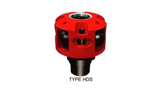
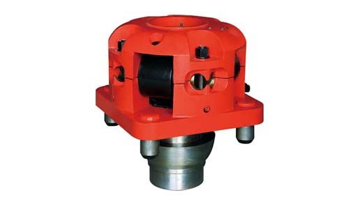
The JOTKB MODEL 27 PDHD OR 20 PDHD are developed for pin drive master bushing for rotary table sizes from 27-1/2" to 49-1/2" having 25-3/4" and 23" dia pin center. This unit is used for heavy duty drilling operations and high torque conditions on off shore as well as on shore drilling operations, and handle Kelly sizes from 3" to 6" Square or Hexagonal.

American Block offers a complete line of drilling rotary tables that range from 17 ½ to 60 ½ . These tables are designed to withstand the harshest drilling conditions. All rotary tables feature a fabricated frame, heavy duty main thrust bearing and precision machined spiral bevel gear that results in superior strength, toughness and durability.
American Block can also provide unitized rotary table assemblies (IRD). Our unitized skid packages are ideal for new builds or can be retrofitted to existing rigs. Featuring a heavy-duty oilfield skid and an extend life transmission. The rugged design ensures that when the equipment is mounted it remains rigid during operation and rig moves. Other rotary table options include hydraulically operated tables and high torque tables (25% more torque), which are ideally suited for top drive operation.
Please send us your inquiry with detail item description or with Model number. If there is no packing demand we take it as our regular exported standard packing. We will offer you an order form for filling. We will recommend you the most suitable model according to information you offered.
We can give you really high quality products with competitive price. We have a better understanding in Chinese market, with us your money will be safe.

Jiangsu Xinxiang share Co., Ltd was founded in 1994, its predecessor was established in 1955, it‘s located in high-tech industrial concentration zone of Nantong City, Jiangsu Province; near to a new developing international deep-water port Yangkou Port which commitment to ship 200,000 tons goods; world famous modern city Shanghai is only 2.5 hours away from it by car; company registered capital is 60,000,000 RMB, the total assets is 119.85 million RMB, it covers an area of 160,000 square meters and currently over 500 employees. Jiangsu Xinxiang Share Co., Ltd is "self-import and export enterprise", "private technology enterprises in Jiangsu Province", "high-tech enterprises in Jiangsu Province", it is top ten companies of the first national large and medium-sized industrial enterprises in independent innovation capacity of the industry; it accessed to API7, 7K, 8A, 8C, and has the right to use the logo, and also passed the ISO9001:2000 quality system certification in the earlier stage within the same industry.
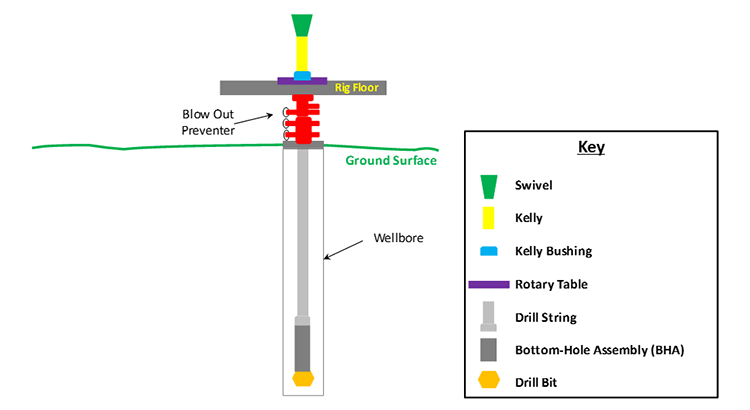
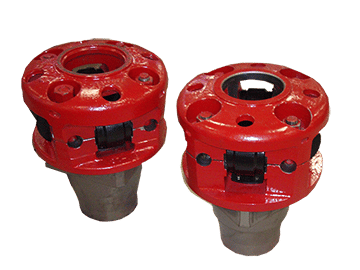
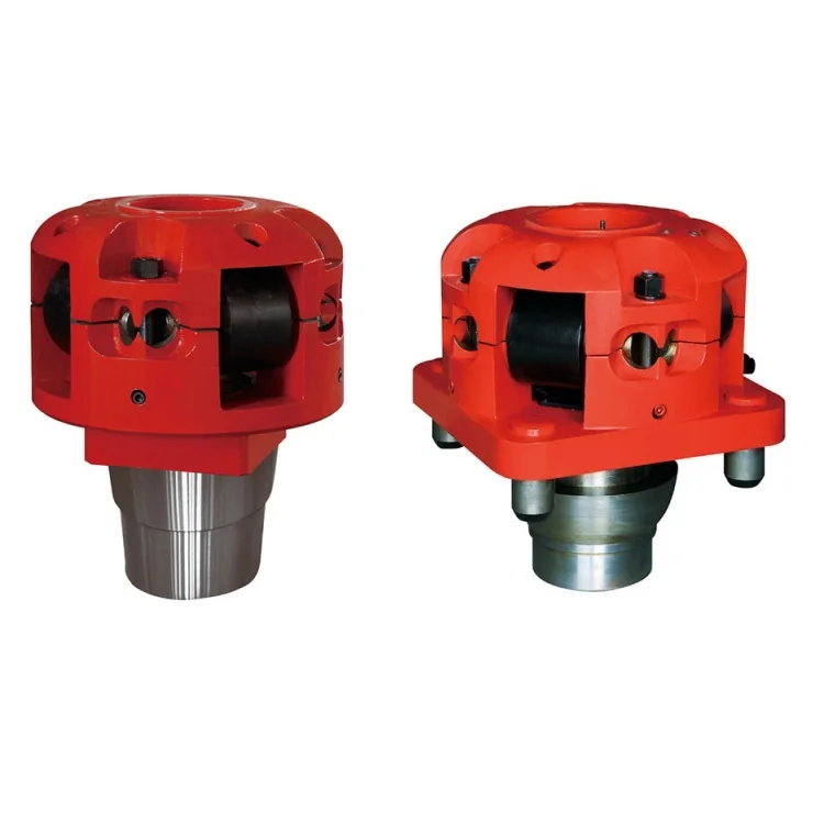
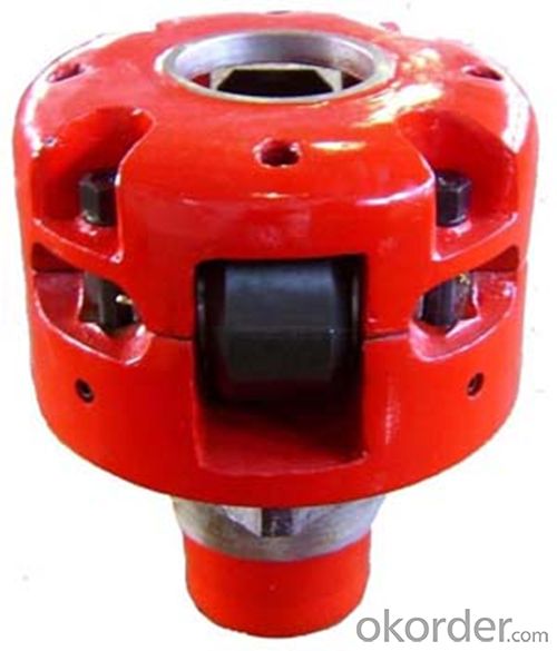
A kelly drive is a type of well drilling device on an oil or gas drilling rig that employs a section of pipe with a polygonal (three-, four-, six-, or eight-sided) or splined outer surface, which passes through the matching polygonal or splined kelly (mating) bushing and rotary table. This bushing is rotated via the rotary table and thus the pipe and the attached drill string turn while the polygonal pipe is free to slide vertically in the bushing as the bit digs the well deeper. When drilling, the drill bit is attached at the end of the drill string and thus the kelly drive provides the means to turn the bit (assuming that a downhole motor is not being used).
The kelly is the polygonal tubing and the kelly bushing is the mechanical device that turns the kelly when rotated by the rotary table. Together they are referred to as a kelly drive. The upper end of the kelly is screwed into the swivel, using a left-hand thread to preclude loosening from the right-hand torque applied below. The kelly typically is about 10 ft (3 m) longer than the drill pipe segments, thus leaving a portion of newly drilled hole open below the bit after a new length of pipe has been added ("making a connection") and the drill string has been lowered until the kelly bushing engages again in the rotary table.
The kelly hose is the flexible, high-pressure hose connected from the standpipe to a gooseneck pipe on a swivel above the kelly and allows the free vertical movement of the kelly while facilitating the flow of the drilling fluid down the drill string. It generally is of steel-reinforced rubber construction but also assemblies of Chiksan steel pipe and swivels are used.
The kelly is below the swivel. It is a pipe with either four or six flat sides. A rotary bushing fits around the flat sides to provide the torque needed to turn the kelly and the drill string. Rollers in the bushing permit the kelly free movement vertically while rotating. Since kelly threads would be difficult to replace, normally the lower end of the kelly has saver sub — or a short piece of pipe — that can be refurbished more cheaply than the kelly. Usually, a ball valve, called the lower kelly cock, is positioned between the kelly and the kelly saver sub. This valve is used for well control if the surface pressure becomes too high for the rotary hose or surface conditions.
According to the ″Dictionary of Petroleum Exploration, Drilling and Production″, ″[The] kelly was named after Michael J. (King) Kelly, a Chicago baseball player (1880-1887) who was known for his base running and long slides.″
ROTARY TABLE MASTER BUSHING Filed oct. 22, 1965 4 sheets-sneer 4 BY a@ United States Patent O 3,386,263 ROTARY TABLE MASTER BUSHING Spencer W. Long, Inglewood, Calif., assiguor to Armco Steel Corporation, Middletown, Ohio, a corporation of Ohio Filed Oct. 22, 1965, Ser. No. 501,565 16 Claims. (Cl. 64I-23.5)
ABSTRACT OF THE DISCLOSURE The master bushing assembly for a well drilling rotary machine comprises duplicate split halves each having a laterally extending driving lug provided with a radial driving face, the master bushing halves each lbeing rovi-ded with axially extending pin sockets for reception of driving7 pin-s on a kelly bushing.
This invention relates to well drilling apparatus and is particularly directed to a novel -form of rotary table and bushings for turning the kelly and handling drill pipe.
In -conventional apparatus, the master bushing rests in the rotary table and is provided with a tapered bore to receive wedge-shaped pipe-gripping slips for engaging the outer surface of drill pipe. The master bushing is s-plit axially into two sections to `facilitate removal from the rotary table so that the maximum opening in the rotary table may be used when lowering the bit through the rotary table. The split master bushing is commonly yprovided with a square portion which is received within a square recess in the rotary table, so that the rotary table may turn the master bushing. The kelly drive bushing has been driven by a similar square recess in the master bushing, or by parallel downward extending drive pins. Drive pins on. the kelly bushing are often used when deep drilling operations require a long tapered bore in the master bushing to accommodate long drill pipe slips; in such case the tapered bore extends to the top surface of the master bushing, thereby preventing the use of a drive square in the master bushing.
Heretofore the drive pins on the kelly bushing have been successfully used only with solid master bushings. These solid master bushings have been used to provide accurate spacing for the drive pin sockets and to provide solid support for long drill pipe slips and heavy loads. Solid master bushings have the disadvantage of being awkward to handle, and being time-consuming to remove and replace when large diameter bits, tools, casing, etc. are to be lowered through the rotary table.
The principal object of this invention is to provide a split type master bushing which will remain firmly seated in the rotary table opening and maintain accurate location and spacing of pin sockets for kelly bushing drive pins under forces exerted when d-riving the kelly and which will rigidly support the slips when handling drill pipe. The master Ibushing has a circular shape with external diameters substantially equal to the central openings in the rotary table to provide solid .backing for drill pipe slips, and to maintain the pin drive sockets for the kelly bushing in accurate location. Each master bushing section has a single outward extending driving lug, and the conventional drive square is eliminated. The driving lugs and the sockets for the drive pins of the kelly bushing are so located on the .master bushing sections that the driving forces act to keep the bushing sections seated against the table opening and act to maintain accurate spacing of the drive pin sockets.
In the drawings, FIGURE 1 is a sectional elevation ICS showing a preferred form of the invention and taken substantially on the lines 1-1 as shown in FIGURE 2.
FIGURES 6, 7 and 8 are diagrammatic illustrations showing how the driving forces between the table `and the master bushing sections and between the ma-ster bushing sections and the kelly bushing are of .a direction and location to force the master bushing sections outward against the central opening in the rotary table.
FIGURES 9, 10 and 11 show similar force diagrams for a master bushing having a conventional square drive from the rotary table, and kelly bushing drive pin socket locations identical to those of FIGURES 6, 7 and 8.
Referring to the drawings, the rotary machine generally designated 10 includes a stationary base 11 and a rotary ta"ble `12. A bearing Iassembly 13 on the base 11 supports the table 12 for rotary movement. A ring gear 14 xed on the table is driven by a pinion gear 15 xed on a pinion shaft 1-6 rotatably supported on the ibase 11.
The rotary table 12 is provided with a stepped central vertical opening 17 and 17a extending there-through. Drive pockets 18 and 19 are provided in the rotary table 12 at diametrioally opposed positions and each extends to the upper surface 20 of the rotary table. Each pocket yalso extends to the central opening 17. Each of the pockets has -a radial vwall 21, 22.
A master bushing assembly generally designated 24 is split longitudinally to form a pair of duplicate master bushing sections 25 and 26 having confronting faces 27, 28 and 29, 30. The outer 4surfaces 31, 31a of the bushing sections are circular and they are adapted to be received and supported on the shoulder 23 joining the parts of the stepped central opening 17, 17a in the rotary table 12.
Each bushing section has a single driving lug 32, 33, extending outward beyond the outer surface of the bushing section and received in one of the drive pockets 18, 19. The driving lug 32 extends into pocket 18 between the radial wall 21 and the clearance wall 21a spaced therefrom, and is -provided with a radial face 34 for engagement with the radial wall 21 of the pocket 18. Similarly, the driving lug 33 extends into the pocket 19 between the radial wall 22 and the clearance wall 22a spaced therefrom, and has a radial face 35 which contacts the radial wall 22 of the pocket 19. When the parts are in the position shown in the drawings, the radial faces 34 and 35 of the driving lugs 32 and 33, the radial walls 21 and 22 of the table pockets 18 and 19, the radial face 27 of the bushing section 25 and radial face 30 of the bushing section 26 all lie in Vthe same vertical plane which passes through the rotary axis of the rotary table 12. The surface 29 on the bushing section 25 and the surface 28 on the bushing section 26 lie on opposite sides of this common plane and have a small clearance space therewith, which clearance space facilitates installation and removal of the bushing sections with respect to the rotary table 12.
The master bushing sections 25 and 26 cooperate to define a central tapered bore 37 for reception of wedgeshaped pipe-engaging slips, not shown. The central bore 37 extends to the upper surface of the master bushing and its taper portion is relatively long in order to accommodate the long slips employed for gripping heavy strings of pipe. A kelly bushing generally designated 39 is provided with a pilot skirt 40 which extends into the bore 37. The kelly bushing 39 rests on the upper surface of the master bushing 24 and is provided with rollers 41 which engage the faces of the kelly 38. The kelly bushing 39 is provided with four equally spaced downward extending parallel drive pins 42, and these drive pins are received in upward opening sockets 43, 44, 45, 46 provided on the master bushing 24. The pin sockets 43 and 44 are located on the bushing section 25 and the pin sockets 45 and 46 are located on the bushing section 26. Driving torque transmitted by the pinion 15 to the ring gear 14 causes the rotary `table 12 to drive the lugs 32 and 33 on the master bushing sections and these in turn drive the kelly bushing 39 through the drive pins 42. The rollers 41 apply driving torque to turn the kelly 38 while at the same time permitting it to move freely in a vertical direction.
The locations of the pin sockets 43, 44, 45 and 46 on the master bushing sections 25 and 26 are not symmetrical with respect to each bushing section but on the contrary the pin socket 43 is located close to the surface 29 on the bushing section 25, and the pin socket 45 is located close to the surface 28 on the bushing section 26. The pin socket 43 on the bushing section 25 is remote from the driving lug 32 on that same bushing section. Similarly, Vthe pin socket 45 on the bushing section 26 is remote from the driving lug 33 on the same bushing section. Pin socket 44 is located 90 degrees from pin socket 43, and similarly, pin socket 46 is located 90 degrees from pin socket 45.
FIGURES 6, 7 and 8 are force diagrams showing how this arrangement of drive lugs and sockets results in holding the master sections in solid engagement with the rotary table opening 17 under the driving forces imparted by the rotary table to the master bushing sections and by the master bushing sections to the kelly bushing 39. In FIGURE 6 the force P represents the driving force applied by the rotary table 12 to the driving lug 32 on the master bushing section 25. The force Q represents the driving reaction from a kelly drive pin 42 in the socket 44, assuming that all force between kelly bushing 39 and master bushing section 25 is taken by this particular socket. The force R is the reaction of the rotary table 12 against the master bushing section 25, resulting from the yforces P and Q. In FIGURE 7, force P is the same but the forces Q1 and Q2 assume that the sockets 44 and 43 are equally loaded. The force R1 represents the reaction of the rotary table 12 against the master bushing section 25 resulting from the forces P, Q1 and Q2. In FIGURE 8, the force P is the sarne and the force Q represents the driving reaction on the socket 43, assuming that this socket carries all of the force between kelly bushing 39 and master bushing section 25. The force R2 is the reaction of the rotary table 12 against the master bushing section 25 resulting from the forces P and Q. In all three views, FIGURES 6, 7 and 8, it is apparent that the reaction forces R, R1, Rzof the rotary table 12 against the master bushing section 25 are toward the axis of rotation and not away from it. In other words, the driving forces from the rotary table 12 and the driving reactions from the kelly bushing 39 are of a direction and location to force the master bushing section 25 outward against the circular bore in the rotary table 12. Since the bushing section 26 is a duplicate of the bushing section 25, the same forces and reactions occur and both bushing sections are held in solid engagement with the bore of the rotary table by reason of the driving forces and reactions. Although the force diagrams of FIGURES 6, 7 and 8 do not take into account the action of centrifugal force, such centrifugal force serves to supplement the action of maintaining the split master bushing sections 25 and 26 in contact with the circular opening in the rotary table 12.
The force diagrams of FIGURES 9, 10 and 11 show the distribution of driving forces on a split master bushing construction having conventional square driving faces and kelly bushing drive pin socket locations identical to those of FIGURES 6, 7 and 8. The conventional rotary table 12a has a square recess 50 in its upper surface and this recess has parallel faces 51 and 52 and parallel faces 53 and 54. The corners of the square are beveled olf to provide clearance spaces 55. The split master bushing sections 56 and 57 have a conventional square shape with the corners beveled away. In this construction, location of the pin sockets 43a and 44a in the same relative position as that shown in FIGURES 6, 7 and 8 does not result in holding the master bushing sections in solid engagement with the rotary table 12a in all cases. In FIGURE 9, it is assumed that all of the driving reaction -is taken by the socket 44a. This compares to FIGURE 6. In FIG- URE 10, it is assumed that half of the total driving reaction is taken by each socket 43a and 44a. This compares to FIGURE 7. In FIGURE 11, it is assumed that all of the driving reaction is taken by the socket 43a. In FIGURE 9 the driving force P1 would have to be equal to and colinear with driving reaction Q to prevent inward displacement of master bushing section 56 relative to rotary table 12a. Since angle A is much greater than the angle of friction for the contacting surfaces of master bushing section 56 and rotary table 12a, driving force P1 cannot be colinear with driving reaction Q. Hence in FIGURE 9 inward displacement of master bushing section 56 relative to rotary table 12a is not prevented. Since both centrifugal force on master bushing section 56 and driving reaction Q are variable, alternate inward and outward displacement of master bushing section 56 relative to rotary table 12a would occur, thereby causing misalignment and producing excessive wear. Inspection of the force diagram of FIGURE 10 reveals that a similar though not so pronounced tendency toward inward displacement of master bushing section 56 relative to rotary ta"ble 12a exists. No such tendency exists when all of the driving reaction between master bushing section 56 and kelly bushing 39 is taken by socket 43a as shown in FIGURE 11.
Due to manufacturing inaccuracies and wear of parts, the direction and location of the resultant forces will vary between the extremes shown in FIGURES 6, 7 and 8 for the device embodying this invention, and will vary between the extremes shown in FIGURES 9, 10 and 11 for the conventional square drive with kelly bushing drive pin sockets located as shown. With the split circular master bushing shown in FIGURES 6, 7 and 8, the driving forces and centrifugal force will always tend to hold the bushing sections outward against the opening in the rotary table, but with the construction shown in FIG- URES 9, 10 and l1, alternate inward and outward displacement of the master bushing sections 56 and 57 occurs within the rotary table drive recess 50.
From a consideration of the force diagrams of FIG- URES 6, 7, and 8, it is apparent that the maximum benets in maintaining each master bushing section in contact with the rotary table opening is achieved when the pin drive socket remote from the driving lug on that section is positioned as close as practicable to the confronting faces of the master bushing sections.
The sections 25 and 26 of the master bushing 24 may be removed separately from .the opening 17 in the rotary table 12, after the kelly bushing 39 and kelly 38 have been removed. As shown in FIGURE 2, openings 59 are provided in the upper surface of each master bushing section, and a pair of hooks on a sling (not shown) may be inserted into these openings. The location of the openings 59 is chosen so that tilting movement of each bushing is minimized when it is lifted by hooks inserted into these openings.
In order to facilitate installation and removal of the master bushing sections 25 and 26 with respect to the vrotary table 12, the outer wall 61 of each bushing section, which wall is otherwise circular, is provided with a straight portion 62 at a location remote from the driving lug on that bushing section. A clearance space 63 is thus formed between the short straight portion 62 and the circular opening 17 in the rotary table 12. This clearance space 63 insures that adequate clearance develops/ between the circular opening 17 and the outer circular wall 61 of the bushing section when the bushing section swings through a small arc around the corner 64 at the intersection of the opening 17 and the radial face of the driving lug.
Means are provided for releasably latching the master bushing sections 2S and 26 against upward movement relative to the rotary table 12. As shown in FIGURE 3, this means includes a latch actuating pin 66 mounted to turn and slide vertically within aligned openings 67 and 68 on the bushing section 26. The latch pin 66 has an integral enlarged head 69 of non-circular outline and resting in the non-circular recess 70 provided in the upper surface of the bushing section. The pin 66 is slidably keyed to the latch element 71 which has a projecting portion 72 adapted to enter the latch recess 73 provided on the rotary table 12. When the latch is to be operated, the enlarged head 69 is grasped manually, lifted upward out of the recess 70, and then turned one-quarter turn. This moves the projecting portion 72 of the latch element 71 into or out of the latch recess 73. The head 69 is then allowed to descend by gravity back into the non-circular recess 70 to hold the latch element 71 in selected position. A weld bead 74 is provided to limit upward travel of the head 69 and latch pin 66.
In a modified form of the invention shown in FIGURES 12-15, the rotary table and the outer shape of the master bushing sections and the location of the pin drive sockets is the same as that previously described, but a split liner is provided within the central tapered bore dened by the master bushing sections. The master bushing sections are shown at 25a and 26a and each is provided with a single outward extending driving lug 32a and 33a as previously described. Split liner sections 75 and 76 are duplicates and are mounted within the central tapered bore 37a defined by the master bushing sections 25a and 26a. A positioning lug 77 on each liner section and a mating recess 78 on each master bushing section as shown in FIGURE l5 insures that the confronting faces 79 on the liner sections will always be perpendicular to the confronting faces 80 on the master bushing sections, This insures that both liner sections 75 and 76 must be removed from rotary table 12 before removing either master bushing section 25a or 26a, and thus any possibility of accidentally dropping the liner section down through the rotary table is eliminated.
When the liner sections 75 and 76 are removed, the tapered bore 37a in the master bushing sections may be employed with slips for handling large diameter pipe. A pair of hook receiving openings 81 are provided on each liner section to facilitate lifting it from the tapered bore in the master bushing sections. Also latch means are provided for latching the liner sections against upward movement relative to the master bushing sections. As shown in FIGURE 14, the latch element 71a is slidably keyed on the latch pin 66a so that when the latter is raised and turned by means of the enlarged head 69a the projecting portion 72a is swung into or out of the latch recess 73a.
rotary table having a central circular opening and having a pair of diametrically positioned pockets, each pocket having a radial wall and a clearance wall spaced .therefrom, a master bushing assembly having an outer circular surface mounted in said table opening, said master bushing assembly being split axially to forma pair of bushing sections having spaced confronting surfaces, each bushing section having a driving lug adjacent its confronting surface and extending outward beyond said surface into one of said pockets, respectively, and between the radial wall and clearance wall thereof, each of said lugs having a radial driving face engageable with one of said radial walls, respectively, and having another face spaced from one of said clearance walls, respectively.
2. In a well drilling device, the combination of: a rotary table having a central circular opening and having an upper surface provided with a pair of pockets diametrically positioned and extending into said opening, each pocket having a radial wall and a clearance wall spaced therefrom, a master bushing assembly having an outer circular surface mounted in said table opening, said master bushing assembly being split -axially to form a pair of duplicate bushing sections having spaced confronting surfaces, each bushing section having a driving lug adjacent its confronting surface and extending outward beyond said outer surface into one of said pockets, respectively, and between the radial wall and clearance wall thereof, each of said lugs having a radial driving face engageable with one of said radial walls, respectively, and having another face spaced from one of said clearance walls, respectively.
3. In a well drilling device, the combination of: a rotary table having a central circular opening and having a pair of diametrically positioned pockets, a master bushing assembly having an outer circular surface mounted in said table opening, said master bushing assembly being split axially by parallel offset plane surfaces to form a pair of duplicate bushing sections with clearance between said plane surfaces, each bushing section having a driving lug extending outward beyond said outer surface into one of said pockets, respectively, each of said lugs having a radial driving face forming a continuation of one of said plane surfaces.
4. In a well drilling device, the combination of: -a rotary table having a central circular opening and having an upper surface provided with a pair of pockets diametrically positioned and extending to said opening, each pocket having a radial wall, a master bushing assembly having an outer circular surface mounted in said table opening, said master bushing assembly being split axially by parallel offset plane surfaces to form a pair of duplicate bushing sections with clearance between said plane surfaces, each bushing section having a driving lug extending outward beyond said outer surface into one of said pockets, respectively, each of said lugs having a radial driving face forming a continuation of one of said plane surfaces and engageable with one of said radial walls, respectively.
5. In a well drillin-g device, the combination of: a rotary table having a central circular opening and having a pair of diametrically positioned pockets, each pocket having a radial wall, a master bushing assembly having an outer circular surface mounted in said table opening, said master bushing assembly being split axially to form a pair of duplicate bushing sections with confronting surfaces, each bushing section having a driving lug extending outward beyond said outer surface into one of said pockets, respectively, each of said lugs having a radial driving face engageable with one of said radial walls, respectively, the outer circular surface of each master bushing section being relieved at a location adjacent a confronting surface and remote from the lug on that master bushing section, whereby clearance spaces are formed within the circular opening of the rotary table to facilitate removal of the master bushing sections from the rotary table opening.
rotary table having a central circular opening and having a pair of diametrically positioned pockets, each pocket having a radial wall, a master bushing assembly having an outer circular surface mounted in said table opening and having a central bore, said master bushing assembly being split axially to form a pair of duplicate bushing sections with confronting surfaces, each bushin-g section having a driving lug extending outward beyond said outer surface into one of said pockets, respectively, each of said lugs having a radial driving face engageable with one of said radial walls, respectively, a liner having a taper bore and mounted in the central bore of the master bushing assembly, the liner being split axially to form duplicate liner sections with confronting surfaces, and interengaging means on the liner and master bushing sections acting to maintain the confronting surfaces of the liner at right angles to the confronting surfaces on the master bushing sections.
7. For use with a well drilling rotary table, having a central circular opening, the combination of: a master bushing assembly having a circular outer surface for reception in the circular opening o-f the table, said master bushing assembly being split axially by parallel offset plane surfaces to form a pair of duplicate bushing sections with clearance between said plane surfaces, each bushing section having a driving lug extending outward beyond said outer circular surface and having a radial driving face forming a continuation of one of said plane surfaces.
8. For use with a well drilling rotary table having a central circular opening, the combination of: a master bushing assembly having a circular outer surface for reception in the circular table opening, said master brushing assembly being split axially to form a pair of duplicate bushing sections having confronting surfaces, each bushing section having a driving lug extending out-ward beyond said outer circular surface and having a radial driving face forming a continuation of one of the confronting surfaces, the outer circular sur-face of each master bushing section being relieved at a location adjacent a confronting surface and remote from the lug on that master bushing section, whereby clearance spaces are formed within the circular opening of the rotary table to facilitate removal of the master bushing sections from the rotary table opening.
9. For use with a well drilling rotary table having a central circular opening, the combination of: a master bushing assembly having an outer surface for reception in the table opening and having a central bore, said master bushing assembly bein-g split axially to lform a pair of duplicate bushing sections, each bushing section having a drivin-g lug extending outward beyond said outer surface and having a radial driving face adjacent one of the confronting surfaces, a liner having a taper bore and mounted in the central bore of the master bushing assembly, the liner` being split axially to `form duplicate liner sections with confronting surfaces, and interengaging means on the liner and master bushing sections acting to maintain the confronting surfaces of the liner at right angles to the confronting surfaces on the master bushing sections.
10. In a well drilling device, the combination of: a rotary table having a central circular opening, a master bushing assembly having an outer circular surface mounted in said table opening, said master bushing assembly being split axially to form a pair of bushing sections, means for driving each master bushing section from said table, a kelly bushing having four parallel downward extending equally spaced driving pins, said master bushing sections each having two pin sockets for reception of said driving pins, one of said pin sockets on each bushing section lying substantially closer than the other pin socket to the other bushing section.
11. In a well drilling device, the combination of: a rotary table having a central circular opening, a master bushing assembly having an outer circular surface mounted in said table opening, said master bushing assembly being split axially to form a pair of duplicate bushing sections having confronting surfaces, means for driving each bushing section from said table, a kelly bushing having four parallel downward extending equally spaced driving pins, said master bushing sections each having two pin sockets for reception of said driving pins, one of said pin sockets on each bushing section lying substantially closer than the other pin socket to said confronting surfaces.
12. In a `well drilling device, the combination of: a rotary table having a central circular opening and having a pair of diametrically positioned pockets, a master bushing assembly having an outer circular sur-face mounted in said table opening, said master bushing assembly being split axially to form a pair of duplicate bushing sections having confronting surfaces, each bushing section having a driving lug extending outward beyond said outer surface into one of said pockets, respectively, a kelly bushing having four parallel downward extending equally spaced driving pins, said master bushing sections each havin-g two pin sockets for reception of said driving pins, one of said pin sockets on each bushing section lying substantially closer than the other pin socket to said confronting surfaces.
rotary table having a central circular opening and having an upper surface provided with a pair of pockets diametrically positioned and extending to said opening, each pocket having a radial wall, a master bushing assembly having an outer circular surface mounted in said table opening, said master bushing assembly being split axially to form a pair of duplicate bushing sections having confronting surfaces, each bushing section having a driving lug extending outward beyond said outer surface into one of said pockets, respectively, each lug having a radial driving face engaging one of said radial walls, respectively, a kelly bushing having four parallel downward extending equally spaced driving pins, said master bushing sections cach having two pin sockets -for reception of said driving pins, one of said pin sockets on each bushing section being positioned adjacent to said confronting surfaces, and the other pin socket on each bushing section being remote from said confronting surfaces.
14. For use with a well drilling rotary table having a circular central opening, the combination of: a master bushing assembly adapted for reception in the table opening, said master bushing assembly having an upper sur- -face provided with four equally spaced upward opening parallel pin sockets, said master bushing assembly being split axially to form a pair of bushing sections, each with two of said pin sockets, one of said pin sockets on each master bushing section lying substantially closer than the other pin socket to the other bushing section, and each master bushing section having means whereby it may be driven from the rotary table.
15. For use with a well drilling rotary table having a circular central opening, the combination of: a master bushing assembly adapted for reception in the table opening, said master bushing assembly having an -upper surface provided with four equally spaced Iupward opening pin sockets, said master bushing assembly being split axially to form a pair of duplicate bushing sections having confronting surfaces, each master bushing section having two of said pin sockets, one of said pin sockets on each master bushing section lying substantially closer than the other pin socket to said confronting surfaces, and each master bushing section having means whereby it may be driven from said rotary table.
16. For use with a well drilling rotary table having a circular central opening, the combination of: a master bushing assembly adapted for reception in the table opening, said master bushing assembly having an upper surface provided with four equally spaced upward opening pin sockets, said master bushing assembly being split axially to form a pair of duplicate bushing sections having confronting surfaces, each bushin-g section having an outward extending driving lug adjacent said confronting surfaces whereby the bushing section may be driven from 1,892,690 1/ 1933 Witkin 64-23.5 the rotary table, each master bushing section having two 1,976,057 10/ 1934 Zilen 64-23.7 of said pin sockets, one of said pin sockets on each bush- 2,075,028 3/ 1937 Driscoll 64-23.5 ing section lying remote =from the driving lug and sub- 2,183,012 12/ 1939 Davidson 64-23.5 stantially closer than the other pin socket to said con- 5 2,204,645 6/ 1940 Baash 64-23.5 fronting surfaces. 2,306,130 12/1942 Long 64-23.7 2,344,746 3/ 1944 Spalding 64-23.5


 8613371530291