
kelly bushing depth manufacturer
An adapter that serves to connect the rotary table to the kelly. The kelly bushing has an inside diameter profile that matches that of the kelly, usually square or hexagonal. It is connected to the rotary table by four large steel pins that fit into mating holes in the rotary table. The rotary motion from the rotary table is transmitted to the bushing through the pins, and then to the kelly itself through the square or hexagonal flat surfaces between the kelly and the kelly bushing. The kelly then turns the entire drillstring because it is screwed into the top of the drillstring itself. Depth measurements are commonly referenced to the KB, such as 8327 ft KB, meaning 8327 feet below the kelly bushing.
Kelly bushing is that elevated device positioned right on top of the rotary table and used to transmit torque from the rotary table to the kelly. The kelly bushing is designed to be the connection between the rotary table and the kelly. The kelly is a 4 or 6 sided steel pipe.
The purpose of the rotary table is to generate the rotary action (torque) and power necessary to rotate the drillstring and drill a well. The torque generated by the rotary table is useless if it is not transferred to the kelly (the drillstring is connected to the kelly).
Hence, through the kelly bushing the torque generated at the rotary table is transferred to the kelly. To achieve this connection, the inside profile of the kelly bushing matches the outer profile of the kelly so that the kelly fits or “sits” comfortably in the kelly bushing.
There are various designs for the kelly bushing including the split type, the pin-drive type and the square-drive type. Each of these designs has different ways in which they are connected and disconnected from the rotary table.
The internal diameter of the kelly bushing can be cut into the shape of a square (4-sided) or a hexagon (6-sided) depending on the outer shape of the kelly that will be used. The internals of a Kelly bushing is designed to resemble the outer shape of a Kelly just like the insides of a key lock is cut to exactly match the outer shape of the key.
The kelly bushing is not designed to hold tightly onto the Kelly; the kelly is still permitted to move up and down through the kelly bushing. This requirement is a must since drilling cannot progress if the kelly remains on a fixed spot. As the well is drilled deeper, the kelly also moves downward through the Kelly bushing.
The kelly bushing is sometimes used as a reference point from which depth measurements can be taken. All depths must be recorded with respect to a reference point; the kelly bushing (KB) is one of the depth references used in the oil and gas industry.
The top of the kelly bushing is normally used as the depth reference.For example, 7500ft KB means 7500ft below the kelly bushing or 7500ft measured from the top of the kelly bushing down to that point in the well.
In some other cases, depths could be recorded as 7500ft MDBKB meaning 7500ft measured depth below the kelly bushing. This is mostly used when the measured depth is different from the true vertical depth of the well, common with deviated and horizontal wells.
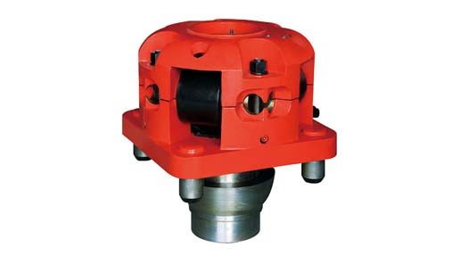
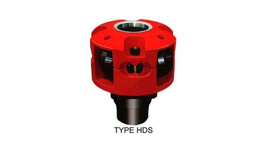
Roller Kelly Bushings are designed and manufactured as per API Spec 7K "Drilling and Well Servicing Equipment" for driving Kelly in the drilling operation.
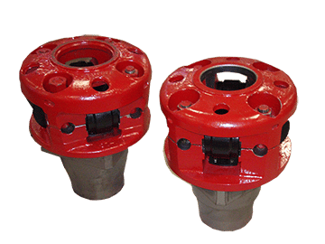
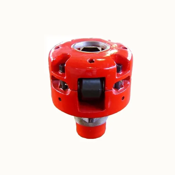
Roller kelly bushings are constructed in upper body half, low body half, rollers, rollers pin and etc., can be available in square drive or pin drive. Square drive roller kelly bushing designed with taper contact surface in low body half, while pin drive roller kelly bushing designed with pin to be installed in low body half.
According to torque of drilling, roller kelly bushing can be available in heavy duty, medium duty and light duty, heavy duty bushings are for high torque and high speed drilling operations while medium duty and light duty are for medium or shadow depth drilling operations.
Roller kelly bushings can accommodate square Kelly or hex Kelly, for square Kelly, the bushing is designed with four flat rollers, and for hex Kelly, the bushing is designed with two V-shaped rollers and two flat rollers. By changing roller size, roller kelly bushing can accommodate square Kelly from 2½" to 5¼" or hex Kelly from 3" to 6", and can be installed in rotary table range from 17½" to 37½".
"I am very satisfied with both the service and professionalism that Total Depth Tools has provided. I have had a personal and business relationship with Jeremiah Belk for several years and will continue to use him for my drill pipe and miscellaneous equipment purchases in the future. Jeremiah is steadfast in his approach and always follows through with his promises. Total Depth Tools offers great communication, has a fast turnaround on quotes/orders, and provides excellent prices! Based on my experience, I am confident in my recommendation of Total Depth Tools and their products."

In the oil and gas industry, depth in a well is the measurement, for any point in that well, of the distance between a reference point or elevation, and that point. It is the most common method of reference for locations in the well, and therefore, in oil industry speech, "depth" also refers to the location itself.
By extension, depth can refer to locations below, or distances from, a reference point or elevation, even when there is no well. In that sense, depth is a concept related to elevation, albeit in the opposite direction. Depth in a well is not necessarily measured vertically or along a straight line.
Because wells are not always drilled vertically, there may be two "depths" for every given point in a wellbore: the borehole, and the datum and the point in the wellbore. In perfectly vertical wells, the TVD equals the MD; otherwise, the TVD is less than the MD measured from the same datum. Common datums used are ground level (GL), drilling rig floor (DF), Rotary table (RT), kelly bushing (KB or RKB) and mean sea level (MSL).
Although it is an intuitive concept, depth in a well is the source of much confusion because it is frequently not specified correctly. Absolute depth should always be specified with three components:
Example: the top of a reservoir may be found at 1,500 mMDRT in a particular well (1,500 m measured depth below the rotary table), which may be equal to 1,492 mTVDMSL (1,492 m true-vertical-depth below mean sea level) after correction for deviations from vertical.
Well depth values taken during the drilling operation are referred to as "driller"s depth". The "total depth" for the well, core depths and all analysis of core / mud and other materials from the drilling hole are measured in "drillers depth".
Well depth values from the wireline loggers operation are referred to as "logger"s depth". The loggers depth are typically considered more reliable than the drillers depth.
The differences between loggers and drillers depths are due to different stretch in the drilling string when drilling, and the wire line entered into the bore hole during wireline logging operations. This difference is estimated and referred to as "core shift". A core from a certain drillers depth is lined up with a wireline log (loggers depth) and structures in the core are compared with the log and matched.
Sign Convention - Depth increases positive in the downward direction. This may seem intuitive but confusion can arise when using certain references while integrating data from different sources. Workers mapping surfaces typically use elevation which, by convention, increases positive in the upward direction. Be mindful when integrating depth and elevation. For example, shallow wells drilled onshore often encounter reservoir at negative depths when referenced to sea level, mappers would define these same reservoirs at positive elevations when referenced to sea level.
The acronym TVDSS is commonly used in the oil industry to represent TVD minus the elevation above mean sea level of the depth reference point of the well. The depth reference point is the kelly bushing in the United States and a few other nations, but is the drill floor in most places.
Differential (or relative) depths or thicknesses should generally be specified with at least two components: a unit and a path, plus any eventual specifiers to remove any possible ambiguity. No specifier should ever be left "implicit" or "understood". There are cases where a path is not needed and in fact should not be specified, because it is defined by the specifier, e.g. isochore (true stratigraphic thickness, independent of well path or inclination).
The distinction between "loggers" depth" and "drillers" depth" is becoming blurred due to the increasing use of logs acquired while drilling (LWD). At the time of writing, the common practice remains that the petrophysicists or geologists define the "official depths" in a well, and these depths are frequently different from the "drillers" depth", after various corrections, tie-ins, etc., have been applied.
Petrophysicists and drilling operations tend to express depths with reference to the rotary table or the original drill floor; geologists tend to use a common datum such as the mean sea level; geophysicists use the mean sea level. This can introduce much confusion when a unit is not specified with all 3 components: unit, path, and reference.
Special consideration must be given to depth measurement in toe-up laterals (J-profile). In these cases the measured depth will continue to increase while true vertical depth will decrease toward the toe of the wellbore.
Path: common expressions of path are measured depth (MD) – elsewhere often known as along hole depth (AHD) – and true vertical depth (TVD). Note that using TV for true vertical depth is not consistent with the use of MD for measured depth, hence the recommended TVD.
the legal datum offshore Australia is Lowest Astronomical Tide (LAT) – (Ref. 1 & 2). Note that this requirement in itself can cause difficulties as it is difficult to measure offshore and can vary greatly between locations and even with time. There is, however, an advantage to this convention: tidal corrections should always be of the same sign (negative depth), i.e. the sea level is always higher than or equal to LAT.
Common references used in operations include: Rotary Table (RT), Drill Floor (DF), Kelly Bushing (KB), Sea Bottom (SB), Ground Level (GL), Casing Bowl Flange (CBF).
Any combination of unit, path, and reference can be used, as long as they result in fully specified, unambiguous depths. A well may reach to many kilometers.
Specification of an absolute depth: in Figure 1 above, point P1 might be at 3207 mMDRT and 2370 mTVDMSL, while point P2 might be at 2530 mMDRT and 2502 mTVDLAT.
Specification of a differential depth or a thickness: in Figure 2 above, the thickness of the reservoir penetrated by the well might be 57 mMD or 42 mTVD, even though the reservoir true stratigraphic thickness in that area (or isopach) might be only 10 m, and its true vertical thickness (isochore), 14 m.

Kelly Bushing Height (KB): The height of the drilling floor above the ground level. Many wellbore depth measurements are taken from the Kelly Bushing. The Kelly bushing elevation is calculated by adding the ground level to the Kelly bushing height.
1. n. [Drilling] An adapter that serves to connect the rotary table to the kelly. The kelly bushing has an inside diameter profile that matches that of the kelly, usually square or hexagonal. It is connected to the rotary table by four large steel pins that fit into mating holes in the rotary table.
A Kelly bushing (some people call “rotary Kelly bushing”) engages a master bushing via four pins and rollers inside a Kelly bushing to allow a Kelly to move up or down freely while it is rotated or in a static mode. This video demonstrates how to make a connection via a Kelly system.
Kelly bushing is that elevated device positioned right on top of the rotary table and used to transmit torque from the rotary table to the kelly. The kelly bushing is designed to be the connection between the rotary table and the kelly.
1. n. [Drilling] An adapter that serves to connect the rotary table to the kelly. The kelly bushing has an inside diameter profile that matches that of the kelly, usually square or hexagonal. It is connected to the rotary table by four large steel pins that fit into mating holes in the rotary table.
The kelly is used to transmit rotary motion from the rotary table or kelly bushing to the drillstring, while allowing the drillstring to be lowered or raised during rotation.
1. adj. [Drilling] Referring to the condition that occurs when the kelly is all the way down, so drilling progress cannot continue. A connection must be made, which has the effect of raising the kelly up by the length of the new joint of drillpipe added, so drilling can resume.
This means that Top Drives can drill about 90 feet before making a connection, whereas with a Kelly System, you will make a connection at about 30 feet deep. Another difference between a Kelly and a Top Drive is that a Top Drive System allows rotation and circulation while back reaming out of a hole.
Kelly drive system is capable to drill with one single drill pipe. On other hand TDS is capable to drill with drill pipe stand. One drill pipe stand is made of three drill pipe joints together.
Kelly bars operate by transferring the torque and crowd force from a rotary drive tool to the drilling tool. Many kelly bars can be applied to any type of piling rig that is available on the market. Kelly bars can be divided into two main types: friction kelly bars and interlocking kelly bars.
The wear bushing is housed in the head or in the spool and is secured by means of two tie down screws to protect it against damage or wear during drilling. It is installed or retrieved with either a simple installation tool or with the HCC combined tool.
Kelly Saver Subs refer to a sub used between the Kelly or top head drive and the drill pipe. It is usually a pin to pin sub that takes the wear abuse to protect the drill pipe and the drive connection. Mills can furnish these subs along with the fluted, hex, or square Kelly Bar drive itself.
Measured Depth (MD) is the length of the wellbore measured along its length. True Vertical Depth (TVD), is the absolute vertical distance between a datum, such as the rotary table, and a point in the wellbore.
A mechanical device for rotating the kelly. The kelly spinner is typically pneumatic. It is a relatively low torque device, useful only for the initial makeup of threaded tool joints. It is not strong enough for proper torque of the tool joint or for rotating the drillstring itself.
This means that Top Drives can drill about 90 feet before making a connection, whereas with a Kelly System, you will make a connection at about 30 feet deep. Another difference between a Kelly and a Top Drive is that a Top Drive System allows rotation and circulation while back reaming out of a hole.
Kelly bars are key components in the execution of boreholes with hydraulic rotary drilling rigs. They transfer the torque of the rotary drive and the crowd pressure of the crowd system concurrently to the drilling tool.
A kelly drive is a type of well drilling device on an oil or gas drilling rig that employs a section of pipe with a polygonal (three-, four-, six-, or eight-sided) or splined outer surface, which passes through the matching polygonal or splined kelly (mating) bushing and rotary table.
A conventional rotary rig or rotary table rig or kelly drive rig is a drilling rig where the rotation of the drill string and bit is applied from a rotary table on the rig floor.
Kelly drive system is capable to drill with one single drill pipe. On other hand TDS is capable to drill with drill pipe stand. One drill pipe stand is made of three drill pipe joints together.
Kelly bars operate by transferring the torque and crowd force from a rotary drive tool to the drilling tool. Many kelly bars can be applied to any type of piling rig that is available on the market. Kelly bars can be divided into two main types: friction kelly bars and interlocking kelly bars.
At a previous employer a coworker came to me and told me that a group within our company had asked for all the KB (kelly bushing) elevations for every well in Colorado. I replied that it made no sense and asked my coworker to see if the reference elevations were what they really wanted. The coworker returned the next day and indicated that they had insisted on the KB elevations. We supplied the KB elevations and sure enough, about a week later they came back and asked for the reference elevations.
Yes, most logs are measured from the KB. No, never use just the KB. Some logs are measured from the DF (derrick floor), GR (ground), or CHF (casing head flange), and there are a few other strange places logs are measured from. In today’s world, where multiple rigs can drill multiple sections of a well, the KB can have different elevations depending on the run of the log. It’s really important to put things back together on a common reference point so the logs aren’t off and formations can be correlated and depth corrected. (Side note: the definition of MSL, mean sea-level, is also probably a good topic of future discussion. It’s probably not what or where you think it is).
Well depth is a very important piece of information. There are several TDs and several ways to measure them. The major TDs we deal with are the driller’s total depth (DTD) and the logger’s total depth (LTD). In general, the DTD is considered to be the official depth of the well.
A couple of other TDs come into play when you are drilling directional or horizontal wells. MTD is the measured total depth, which is the distance along the wellbore. The other piece of information is the true vertical depth (TVD), which is the distance of the well from the surface. There is actually one other measurement, called true vertical depth subsea (TVDSS), which is the TVD as referenced from the reference elevation. In many instances this ends up with data below the sea level and the values are negative. Think of this like a thermometer, where some values are below zero (below sea-level).
A 27-year-old gas drilling rig worker died on May 23, 2003 from blunt force trauma to the head, neck, and chest during a cleanout operation at the well. At the time of the incident, the victim was working within eight feet of the kelly on the drilling rig floor. Compressed air was used to blow out the conductor pipe, but due to a lack of communication, the compressor was turned on before the valves were prepared to control the flow of debris out of the hole. The excess pressure caused the kelly bushing, drillpipe slips, and debris to be blown out of the rotary table. The victim was struck by these objects and was pronounced dead on arrival to the hospital.
A 27-year-old gas drilling rig worker died on May 23, 2003 from blunt force trauma to the head, neck, and chest after he was struck by the kelly bushing and drillpipe slips. OKFACE investigators reviewed the death certificate, related local news articles, and reports from the sheriff’s office, Medical Examiner, Occupational Safety and Health Administration (OSHA),
At the time of the incident, the rig floor and working surfaces were level and dry; the weather was warm with light to no wind. The victim was working with four other crew members on a gas drilling rig, wearing the necessary personal protective equipment (e.g., steel toe boots, hard hat, eye protection). Prior to the incident, the decedent was assigned the task of driller and was asked to find the bottom of the conductor hole with the kelly (Figure 2). The kelly is used to transmit power (rotary motion) from the rotary table and kelly bushing to the drillstring (Table 1). After unlatching the brake handle, the driller allowed the kelly to free fall to the bottom. The uncontrolled fall caused the kelly to become jammed with debris, such as water, mud, and other material, that had collected in the conductor hole since the time it was originally drilled for the well. As a result, a cleanout operation became necessary. Cleanout procedures involving air or mud drilling fluid are acceptable norms in the oil and gas drilling industry; however, drilling fluid is more commonly used than compressed air.
a large diameter hole, lined with pipe, that varies in depth depending on the local geology; the hole where the crew starts the top of the well; also called a starter hole
a long square or hexagonal steel bar with a hole drilled through the middle for a fluid path; goes through the kelly bushing, which is driven by the rotary table
After the kelly became jammed, a senior driller was assigned to take over the brake handle and kelly; however, the decedent remained approximately eight feet away on the rig floor. A newly hired, yet experienced, derrickman had the job of running the air compressor. While the drillers were switching positions, the derrickman realized that he had not started that particular type of compressor in quite some time and left the rig floor to seek help from another driller onsite.
In normal cleanout operation procedures, certain valves are closed prior to turning on the compressed air, which allows control over the flow of debris out of the hole and into a catch pond. Once the valves are prepared, the driller indicates to the derrickman that the area is ready for the compressed air. At some point between the senior driller preparing for cleanout and the derrickman leaving the floor to turn on the air compressor, there was a lack of communication and the air compressor was activated without the senior driller’s knowledge, prior to the prescribed valves being shut. After starting the air compressor, the derrickman returned to the rig floor and, as he walked to his next assignment, the rotary table erupted. The pressure normally used to complete the cleanout work is a minimum of 20 pounds per square inch. Within minutes, the kelly had pressurized well beyond this point to 150 pounds per square inch. The victim, who was still on the rig floor in close proximity to the kelly, was also unaware that the air compressor had been turned on. The compressed air, at full pressure with no valves closed to control or direct the flow, blew the kelly bushing, drillpipe slips, and debris out of the rotary table; all of which struck and landed on the victim.
In the oil and gas industry, depth in a well is the measurement, for any point in that well, of the distance between a reference point or elevation, and that point. It is the most common method of reference for locations in the well, and therefore, in oil industry speech, “depth” also refers to the location itself.
Because wells are not always drilled vertically, there may be two “depths” for every given point in a wellbore: the measured depth (MD) measured along the path of the borehole, and the true vertical depth (TVD), the absolute vertical distance between the datum and the point in the wellbore. In perfectly vertical wells, the TVD equals the MD; otherwise, the TVD is less than the MD measured from the same datum. Common datums used are ground level (GL), drilling rig floor (DF), rotary table (RT), kelly bushing (KB) and mean sea level (MSL). [1]
Kelly Bushing Height (KB):The height of the drilling floor above the ground level. Many wellbore depth measurements are taken from the Kelly Bushing. The Kelly bushing elevation is calculated by adding the ground level to the Kelly bushing height.
Driller’s Depth below rotary table (DDbrt): The depth of a well or features within the wellbore as measured while drilling. The measured length of each joint of drillpipe or tubing is added to provide a total depth or measurement to the point of interest. Drillers depth is the first depth measurement of a wellbore and is taken from the rotary table level on the rig floor. In most cases, subsequent depth measurements, such as those made during the well completion phase, are corrected to the wellhead datum that is based on drillers depth (reference: Schlumberger Oilfield Glossary).

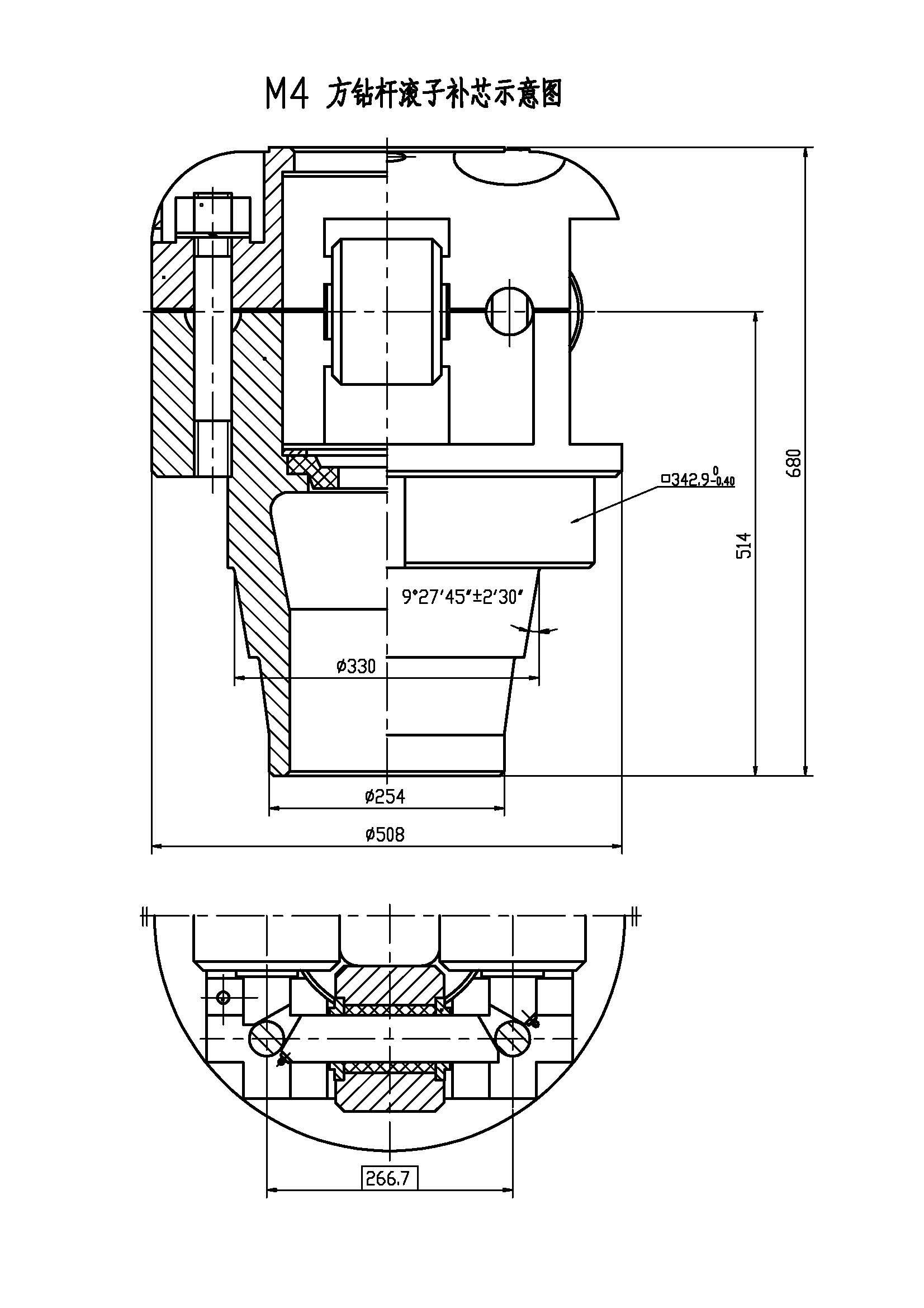
The JOTKB MODEL 27 PDHD OR 20 PDHD are developed for pin drive master bushing for rotary table sizes from 27-1/2" to 49-1/2" having 25-3/4" and 23" dia pin center. This unit is used for heavy duty drilling operations and high torque conditions on off shore as well as on shore drilling operations, and handle Kelly sizes from 3" to 6" Square or Hexagonal.


 8613371530291