
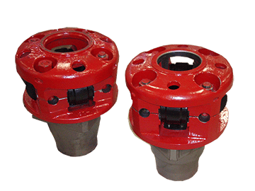
kelly bushing oil and gas factory

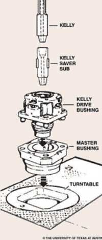
An adapter that serves to connect the rotary table to the kelly. The kelly bushing has an inside diameter profile that matches that of the kelly, usually square or hexagonal. It is connected to the rotary table by four large steel pins that fit into mating holes in the rotary table. The rotary motion from the rotary table is transmitted to the bushing through the pins, and then to the kelly itself through the square or hexagonal flat surfaces between the kelly and the kelly bushing. The kelly then turns the entire drillstring because it is screwed into the top of the drillstring itself. Depth measurements are commonly referenced to the KB, such as 8327 ft KB, meaning 8327 feet below the kelly bushing.
Kelly bushing is that elevated device positioned right on top of the rotary table and used to transmit torque from the rotary table to the kelly. The kelly bushing is designed to be the connection between the rotary table and the kelly. The kelly is a 4 or 6 sided steel pipe.
The purpose of the rotary table is to generate the rotary action (torque) and power necessary to rotate the drillstring and drill a well. The torque generated by the rotary table is useless if it is not transferred to the kelly (the drillstring is connected to the kelly).
Hence, through the kelly bushing the torque generated at the rotary table is transferred to the kelly. To achieve this connection, the inside profile of the kelly bushing matches the outer profile of the kelly so that the kelly fits or “sits” comfortably in the kelly bushing.
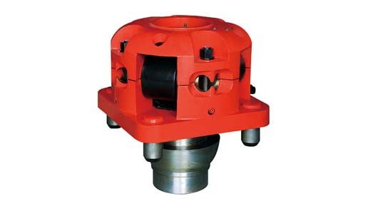
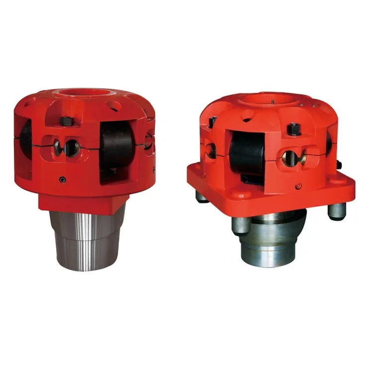
There are various designs for the kelly bushing including the split type, the pin-drive type and the square-drive type. Each of these designs has different ways in which they are connected and disconnected from the rotary table.
The internal diameter of the kelly bushing can be cut into the shape of a square (4-sided) or a hexagon (6-sided) depending on the outer shape of the kelly that will be used. The internals of a Kelly bushing is designed to resemble the outer shape of a Kelly just like the insides of a key lock is cut to exactly match the outer shape of the key.
The kelly bushing is not designed to hold tightly onto the Kelly; the kelly is still permitted to move up and down through the kelly bushing. This requirement is a must since drilling cannot progress if the kelly remains on a fixed spot. As the well is drilled deeper, the kelly also moves downward through the Kelly bushing.
The kelly bushing is sometimes used as a reference point from which depth measurements can be taken. All depths must be recorded with respect to a reference point; the kelly bushing (KB) is one of the depth references used in the oil and gas industry.
The top of the kelly bushing is normally used as the depth reference.For example, 7500ft KB means 7500ft below the kelly bushing or 7500ft measured from the top of the kelly bushing down to that point in the well.
In some other cases, depths could be recorded as 7500ft MDBKB meaning 7500ft measured depth below the kelly bushing. This is mostly used when the measured depth is different from the true vertical depth of the well, common with deviated and horizontal wells.

In the oil and gas industry, depth in a well is the measurement, for any point in that well, of the distance between a reference point or elevation, and that point. It is the most common method of reference for locations in the well, and therefore, in oil industry speech, “depth” also refers to the location itself.
Because wells are not always drilled vertically, there may be two “depths” for every given point in a wellbore: the measured depth (MD) measured along the path of the borehole, and the true vertical depth (TVD), the absolute vertical distance between the datum and the point in the wellbore. In perfectly vertical wells, the TVD equals the MD; otherwise, the TVD is less than the MD measured from the same datum. Common datums used are ground level (GL), drilling rig floor (DF), rotary table (RT), kelly bushing (KB) and mean sea level (MSL). [1]
Kelly Bushing Height (KB):The height of the drilling floor above the ground level. Many wellbore depth measurements are taken from the Kelly Bushing. The Kelly bushing elevation is calculated by adding the ground level to the Kelly bushing height.
Driller’s Depth below rotary table (DDbrt): The depth of a well or features within the wellbore as measured while drilling. The measured length of each joint of drillpipe or tubing is added to provide a total depth or measurement to the point of interest. Drillers depth is the first depth measurement of a wellbore and is taken from the rotary table level on the rig floor. In most cases, subsequent depth measurements, such as those made during the well completion phase, are corrected to the wellhead datum that is based on drillers depth (reference: Schlumberger Oilfield Glossary).
A kelly drive is a type of well drilling device on an oil or gas drilling rig that employs a section of pipe with a polygonal (three-, four-, six-, or eight-sided) or splined outer surface, which passes through the matching polygonal or splined kelly (mating) bushing and rotary table. This bushing is rotated via the rotary table and thus the pipe and the attached drill string turn while the polygonal pipe is free to slide vertically in the bushing as the bit digs the well deeper. When drilling, the drill bit is attached at the end of the drill string and thus the kelly drive provides the means to turn the bit (assuming that a downhole motor is not being used).
The kelly is the polygonal tubing and the kelly bushing is the mechanical device that turns the kelly when rotated by the rotary table. Together they are referred to as a kelly drive. The upper end of the kelly is screwed into the swivel, using a left-hand thread to preclude loosening from the right-hand torque applied below. The kelly typically is about 10 ft (3 m) longer than the drill pipe segments, thus leaving a portion of newly drilled hole open below the bit after a new length of pipe has been added ("making a connection") and the drill string has been lowered until the kelly bushing engages again in the rotary table.
The kelly hose is the flexible, high-pressure hose connected from the standpipe to a gooseneck pipe on a swivel above the kelly and allows the free vertical movement of the kelly while facilitating the flow of the drilling fluid down the drill string. It generally is of steel-reinforced rubber construction but also assemblies of Chiksan steel pipe and swivels are used.
The kelly is below the swivel. It is a pipe with either four or six flat sides. A rotary bushing fits around the flat sides to provide the torque needed to turn the kelly and the drill string. Rollers in the bushing permit the kelly free movement vertically while rotating. Since kelly threads would be difficult to replace, normally the lower end of the kelly has saver sub — or a short piece of pipe — that can be refurbished more cheaply than the kelly. Usually, a ball valve, called the lower kelly cock, is positioned between the kelly and the kelly saver sub. This valve is used for well control if the surface pressure becomes too high for the rotary hose or surface conditions.
According to the ″Dictionary of Petroleum Exploration, Drilling and Production″, ″[The] kelly was named after Michael J. (King) Kelly, a Chicago baseball player (1880-1887) who was known for his base running and long slides.″

The IADC Lexicon is © IADC. However, the documents from which the definitions were drawn may be copyrighted by the original sources, and may not be used without express permission of the copyright holders. IADC expressly recognizes the copyrights of contributors to this Lexicon, including API, OGP, ISO, NORSOK and DNV.
Bushing that rotationally connects the rotary table to the drill string kelly bar, the top of which is commonly used as vertical reference for the drill floor.
Source: API Specification 16Q, Design, Selection, Operation, and Maintenance of Marine Drilling Riser Systems, Second Edition, April 2017. Global Standards
Source: ISO 13624-1:2009, Petroleum and natural gas industries – Drilling and production equipment – Part 1:Design and operation of marine drilling riser equipment. Global Standards

This website uses cookies to improve your experience while you navigate through the website. Out of these cookies, the cookies that are categorized as necessary are stored on your browser as they are essential for the working of basic functionalities of the website. We also use third-party cookies that help us analyze and understand how you use this website. These cookies will be stored in your browser only with your consent. You also have the option to opt-out of these cookies. But opting out of some of these cookies may have an effect on your browsing experience.

Rotary kelly bushing - an adapter that serves to connect the rotary table to the Kelly, which turns the entire drillstring. Depth measurements are commonly referenced to the RKB, such as 10,000 ft. RKB, meaning 10,000 feet below the rotary kelly bushing.
This website is using a security service to protect itself from online attacks. The action you just performed triggered the security solution. There are several actions that could trigger this block including submitting a certain word or phrase, a SQL command or malformed data.
Please send us your inquiry with detail item description or with Model number. If there is no packing demand we take it as our regular exported standard packing. We will offer you an order form for filling. We will recommend you the most suitable model according to information you offered.
We can give you really high quality products with competitive price. We have a better understanding in Chinese market, with us your money will be safe.

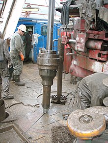
This is the brief explanation of a Kelly rotating system on the rig. Kelly rig is on an old style rigs and nowadays it is mostly used on land operations. For offshore operation, a top drive system is used instead.
First of all, it is important for new people to look at these images before reading the information below because they show the equipment’s name and where they are on the rig.
The upper end of the drill pipe is screwed onto the saver sub. The saver sub is used to protect and minimize wearr and tear on the threads at the bottom of the Kelly. The Kelly is about 40 ft in length with a square or hexagonal shape and it is hollow throughout in order to transport the drilling mud. Kelly moves freely through a Kelly bushing even though the drill stem is rotated.
A Kelly cock valve is located at the top of a Kelly and it is a safety valve which can be closed to stop back pressure from coming back to damage other surface equipment.
A swivel attached to the hook does not rotate, but at the bottom part it supports the Kelly which is being rotated while drilling. Drilling mud is pumped from a mud pump to a stand pipe manifold, Kelly hose and then to a gooseneck connection at a swivel.
A rotary table rotates a Kelly bushing and it simultaneously rotates a Kelly and a drill string and a drill bit. A rotary table has two main functions. The first one is to provide rotation to a drill stem and a bit and the second function is to hold slip in order to support the weight of a drill stem when it is not connected to a Kelly.
Generally, a rotary drive consists of a chain and rotary-drive sprocket. A rotary-drive sprocket is a part of the draw-works. In other rig power systems, an independent electric motor or engine with a direct drive to a rotary table is utilized. For this case, the rotary is normally driven by a drive shaft instead of a chain and rotary-drive sprocket.
A master bushing severs its function as a rotary motion transmission from a rotary table to a Kelly. Additionally, it is a link between a slip and a rotary table.
A Kelly bushing (some people call “rotary Kelly bushing”) engages a master bushing via four pins and rollers inside a Kelly bushing to allow a Kelly to move up or down freely while it is rotated or in a static mode.

At a previous employer a coworker came to me and told me that a group within our company had asked for all the KB (kelly bushing) elevations for every well in Colorado. I replied that it made no sense and asked my coworker to see if the reference elevations were what they really wanted. The coworker returned the next day and indicated that they had insisted on the KB elevations. We supplied the KB elevations and sure enough, about a week later they came back and asked for the reference elevations.
Data sometimes takes on an almost mystical quality, where the meaning and intent have been lost because of inaccurate use or overuse. The oil and gas industry has so many buzz words and so many things that are typically done that we sometimes lose the actual meaning of why or how things are done and worse still, fail to understand the data.
It’s really important to understand the data you’re working with – what it is, where it came from, and what it can be used for. The problem is sometimes actually harder than it seems. If we use the example above, most logs are measured from the KB elevation, correct? So you want KB elevations when normalizing logs to the sea-level datum?
Yes, most logs are measured from the KB. No, never use just the KB. Some logs are measured from the DF (derrick floor), GR (ground), or CHF (casing head flange), and there are a few other strange places logs are measured from. In today’s world, where multiple rigs can drill multiple sections of a well, the KB can have different elevations depending on the run of the log. It’s really important to put things back together on a common reference point so the logs aren’t off and formations can be correlated and depth corrected. (Side note: the definition of MSL, mean sea-level, is also probably a good topic of future discussion. It’s probably not what or where you think it is).
I really like to use the CHF as the reference elevation because after surface casing is run and cemented in, it is a constant point that has a single elevation point throughout the drilling and completion cycle. No matter what the elevation of the rig or completion is, the CHF is always at the same elevation.
So the KB is a physical place on the rig and the reference elevation is the physical place where the log was measured from. They can be the same thing but equating them everywhere will certainly create incorrect data.
Where the elevations come from is another question. Elevations are often supplied on the drilling permit, the completion report, the logs, and probably a couple of other reports.
The elevation starts when the surveyor goes out and measures precisely where the oil and gas company wants the well. Today everything is done by GPS, and the surveyor gets a latitude, longitude, and elevation. At the precise spot, the surveyor pounds a steak into the ground and ties an orange surveyor’s ribbon on it. It’s usually in some pasture and hopefully not on the side of a hill or in the middle of some pond. That does happen, however, despite the fact that the geologist spends months studying the subsurface. The thing is, they probably don’t spend more than 10 minutes looking at the surface.
A day or two before the well spuds, a bulldozer arrives and scrapes the land flat so the rig will have a solid footing while it is drilling the well. The excess dirt gets piled up so that any water gets trapped on site and doesn’t run off to the nearest stream or pond. A curious artifact often appears on one of the piles of dirt – a surveyor’s stake with an orange ribbon on it.
I’ve been at a few rig locations and as I drove on site and glanced over at the surveyor’s stick sitting in the dirt pile, I often wondered how the guys setting up the rig knew the exact spot where the hole was supposed to be located with the location stick sitting far away in the dirt. The answer is they don’t. They position the rig on the pad where it will best fit given the generator, tanks, pipe, and all the other equipment that needs to be located, along with space for parking.
Some companies will actually call back the surveyor to have him give a final elevation of the ground and of the KB and/or DF. If you’re really lucky, the company will have also asked the surveyor to respot the well location so there is an updated lat/long, but don’t count on it. One of the most shocking comments I’ve heard about well locations is, “I don’t worry about well locations anymore because everyone uses a GPS.” Yes, the surveyor used a GPS to place the stake in the ground … just before the bulldozer pushed it into the dirt pile.
If the ground elevation changed between the permit and the completion report, there’s an excellent chance the surveyor came back and resurveyed (and hopefully he also included an elevation to something permanent, like the CHF).
So the question is, now that we have established that we might have several different elevations, what is the best one to use? Oh how I wish that were the only question that needed answering. Elevations are reported to the state and elsewhere from lots of different sources. Permits, completions, activity reports, and logs are the main documents where this data can be found. Locations are a different story, and it is a rare event to see a correction.
The elevations off the log are probably the best to use. Though I have seen them wrong on the log, it’s a rare occurrence. The elevations are generally captured to support the geologist in making structure maps, so there’s a good chance they’ve been checked and verified.
So the next time you are looking for an elevation, ask yourself, what was it referenced to, what document did it come from and, probably most importantly, is it a reasonable value?
Well depth is a very important piece of information. There are several TDs and several ways to measure them. The major TDs we deal with are the driller’s total depth (DTD) and the logger’s total depth (LTD). In general, the DTD is considered to be the official depth of the well.
The LTD is a nice backup that gives confirmation that the DTD is in the ballpark. The DTD and the LTD almost never agree exactly. A lot of that has to do with cable stretch and steel drill pipe. We don’t normally think that steel drill pipe stretches, but when it’s strung together to make a length of 2-4 miles, it does indeed stretch. The pipe is also under immense tension. At the bottom of the drill pipe, near the bit, there’s special drill pipe called drill collars. Drill collars are designed to put weight on the bit and make it drill better. However, rather than adding drill collars or removing them as the well drills, they add more weight than they will ever need at the start of the well and the driller uses a brake that holds the drill string, which prevents all of the weight from ending on top of the drill bit. Too much weight and the bit will not drill straight and it will prematurely wear out the bit. If there is too little weight, the drill bit will not drill efficiently. It is this tension on the drill string that adds to the stretching.
A couple of other TDs come into play when you are drilling directional or horizontal wells. MTD is the measured total depth, which is the distance along the wellbore. The other piece of information is the true vertical depth (TVD), which is the distance of the well from the surface. There is actually one other measurement, called true vertical depth subsea (TVDSS), which is the TVD as referenced from the reference elevation. In many instances this ends up with data below the sea level and the values are negative. Think of this like a thermometer, where some values are below zero (below sea-level).
Operator is another thing that can cause confusion. Current operator and original operator can be two different companies, and often a property can be bought and sold several times. The original operator will have a lot of information with the state because they are the one who filed the permit, completion information, and other initial documentation. The current operator is the one listed on the production data file. If you are trying to match wells, never assume that two different operators are two different wells.
When working between states, well name and lease name will drive you crazy. I haven’t worked everywhere in the U.S., but my experience is they are often equivalent with a couple of exceptions. The lease name is the lessor of the minerals. However, where the state has a well name and a not a lease name, the operator is free to name the well whatever they want. In most cases they use the lease name. However, there are lots of well names with the word “lucky” in them. Prospect names are also used as the well name, which leads to some very interesting well names.
California and a couple of other states require operators to file a permit when plugging wells, recompleting them, or almost anything associated with a well. Other states just require a permit to drill and then have standard forms for plugging and other things.
Understand the origin of the data you are looking at, where it came from, and the correct use of it. Before you do any analysis, know what the limits or reasonable values of the data should be before you start.
John Fierstien is Director of Product Management for P2 Tobin Data. He started his career in oil and gas in 1978 after finishing his MS in Geology from the University of Pittsburgh and his BS in both Geology and Biology from Central Michigan University. He has worked as both a development and exploration geologist. John has been a product manager in oil and gas for the better part of the last 20 years. He’s also spoken at various meetings and conferences and written about sub-surface modeling, oil and gas software, and oil and gas data. John enjoys photography and growing his home automation system. John currently lives west of Austin, in the Texas Hill Country.

To start drilling, a surface drill bit is attached to a bottomhole drill collar, which is in turn attached to the kelly. Once made up, the driller lowers the bit through the rotary table and engages the mud pump(s) and checks for leaks and other abnormalities. The driller lowers the drill string and the kelly bushing is set in the rotary drive bushing and the rotary is engaged. The driller then slowly lowers the bit to bottom and begins the drilling operation.
A heavy, thick-walled tube, usually steel, used between the drill pipe and the bit in the drill stem. It is used to put weight on the bit so that the bit can drill.†
The principal component of a rotary, or rotary machine, used to turn the drill stem and support the drilling assembly. It has a beveled gear arrangement to create the rotational motion and an opening into which bushings are fitted to drive and support the drilling assembly.
A device fitted to the rotary table through which the kelly passes. It is the means by which the torque of the rotary table is transmitted to the kelly and to the drill stem. Also called the drive bushing.†
The large wrenches used for turning when making up or breaking out drill pipe, casing, tubing, or other pipe; variously called casing tongs, rotary tongs, and so forth according to the specific use. Power tongs are pneumatically or hydraulically operated tools that spin the pipe up and, in some instances, apply the final makeup torque.†

v: 1. to assemble and join parts to form a complete unit (for example, to make up a string of drill pipe). 2. to screw together two threaded pieces. Compare break out. 3. to mix or prepare (for example, to make up a tank of mud). 4. to compensate for (for example, to make up for lost time).
n: a device that is attached to the shaft of the drawworks and used as a power source for making up joints of pipe. It is usually located on the driller’s side of the drawworks. Also called spinning cathead.
n: a device that fits into the rotary table to accommodate the slips and drive the kelly bushing so that the rotating motion of the rotary table can be transmitted to the kelly.
n: a drilling rig in which the source of power is one or more internal-combustion engines and in which the power is distributed to rig components through mechanical devices (such as chains, sprockets, clutches, and shafts). Also called a power rig. Compare electric rig.
n: a method of enhanced recovery in which various hydrocarbon solvents or gases (such as propane, LPG, natural gas, carbon dioxide, or a mixture thereof) are injected into the reservoir to reduce interfacial forces between oil and water in the pore channels and thus displace oil from the reservoir rock. See chemical flooding, gas injection.
n: an employee of a drilling fluid supply company whose duty it is to test and maintain the drilling mud properties that are specified by the operator.
n: the recording of information derived from examination and analysis of formation cuttings made by the bit and of mud circulated out of the hole. A portion of the mud is diverted through a gas-detecting device. Cuttings brought up by the mud are examined under ultraviolet light to detect the presence of oil or gas. Mud logging is often carried out in a portable laboratory set up at the well site.
n: an arrangement for producing a well in which one wellbore penetrates two or more petroleum-bearing formations. In one type, multiple tubing strings are suspended side by side in the production casing string, each a different length and each packed to prevent the commingling of different reservoir fluids. Each reservoir is then produced through its own tubing string. Alternatively, a small diameter production casing string may be provided for each reservoir, as in multiple miniaturized or multiple tubingless completions. See dual completion.
The College of Earth and Mineral Sciences is committed to making its websites accessible to all users, and welcomes comments or suggestions on access improvements. Please send comments or suggestions on accessibility to the site editor. The site editor may also be contacted with questions or comments about this Open Educational Resource.
The College of Earth and Mineral Sciences is committed to making its websites accessible to all users, and welcomes comments or suggestions on access improvements. Please send comments or suggestions on accessibility to the site editor. The site editor may also be contacted with questions or comments about this course.

This website is using a security service to protect itself from online attacks. The action you just performed triggered the security solution. There are several actions that could trigger this block including submitting a certain word or phrase, a SQL command or malformed data.


 8613371530291