
single cartridge mechanical seal free sample
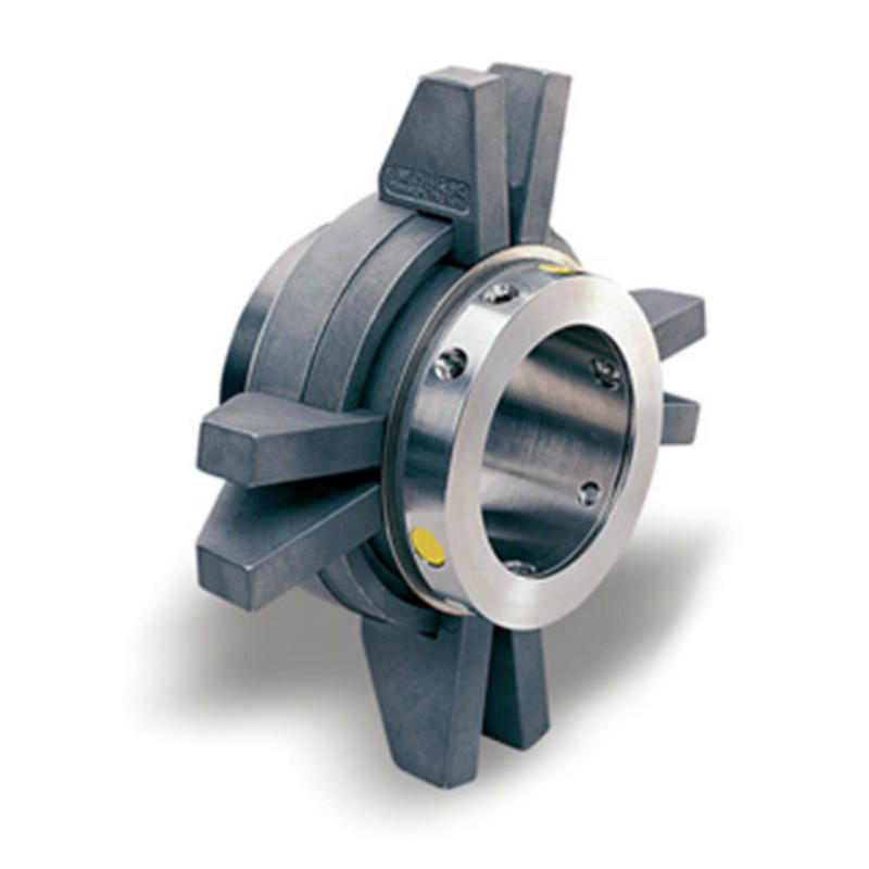
Burgmann cartex single cartridge seal is a world famous cartridge mechanical seal, this seals is popular used for pumps, agitator, mixer, and other rotating machines.
cartex signle cartridge seal is a standard mechanical seal, compared to the modular design with many complex parts, Cartex has been specifically engineered with a simple, robust design to achieve higher overall reliability and performance in extreme conditions.
Guangzhou Lepu machinery CO., LTD becomes one of the leading mechanical seal supplier in south of china, we focus in designing and manufacturing mechanical seal for many kinds of famous brand pumps, our mechanical seal cover many kinds of industry like food, petrol chemical, paper making, sea ship, and so on.
Cartridge seals are a modern alternative designed to eliminate common causes of component seal failure. Check pump unit for defects before installing a cartridge seal to avoid damage to seal parts.
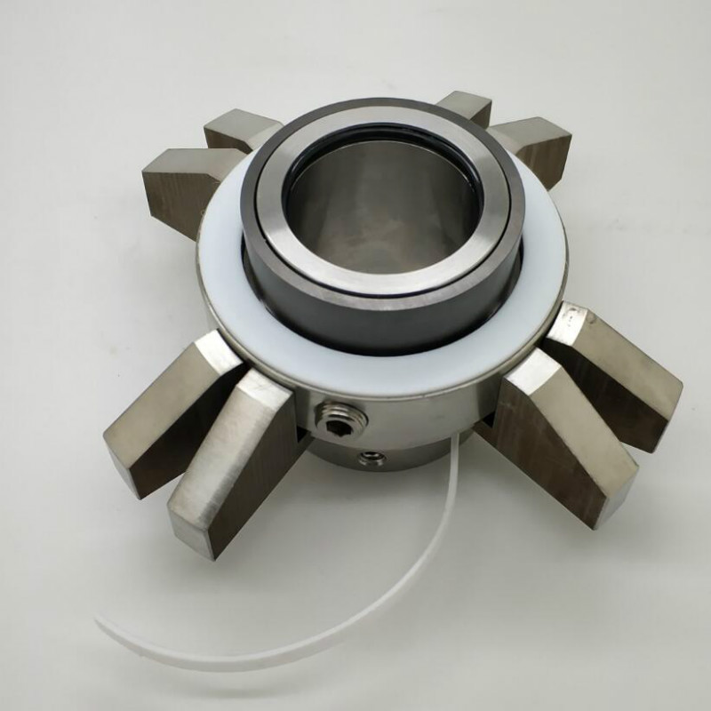
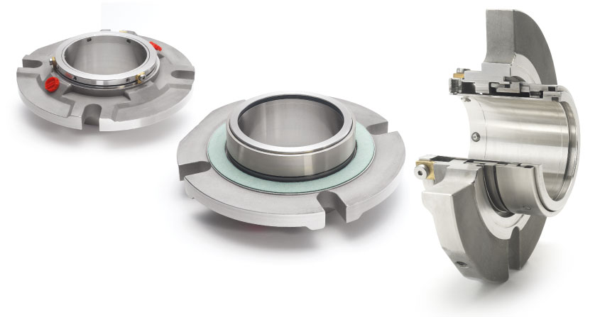
Single cartridge or double cartridge seals are self-contained units comprised of a shaft sleeve, seal, and gland plate. Cartridge seals are fitted onto the pump shaft as a single unit with no further fitting or assembly required.
Modern pumps, compressors, mixers, agitators and other rotary shaft equipment are assembled using either compression pump packing or mechanical seals to minimize emissions and fluid.
Compression pump packing controls leakage whereas mechanical seals will tend to stop any visible leakage all together, keeping work environment clean and hazard free.
Compared to compression packing the initial cost of a mechanical seal is high, however overtime, the associated cost accrued by using compression packing, for example power consumption, maintenance and downtime, could be far in excess of the initial cost of a mechanical seal, which works unattended for a long time.
Flexaseal offers a wide variety of single cartridge mechanical seals, each designed as a reliable solution for the toughest applications. Our single cartridge seals are easy to install and minimize the number of moving parts that can lead to equipment failure. Specially designed single cartridge seals are also available for highly corrosive or high-temperature environments. Cost-effective upgrades are available when circulation, vent, & drain glands are required.

Chesterton is the world leader in design innovation of split seals. Our innovative split seals have been used to seal thousands of process-critical pieces of rotating equipment with exceptional results and many years of leak-free operations.
Chesterton was the first company to offer commercially-viable split seals for plant-wide use, which revolutionized pump sealing across industries. Since that time, we"ve launched a number of innovative split seal designs now used as a standard by companies around the globe. We offer shaft diameters ranging from 25-914 mm (1-36 in.)
A split seal has components split into two equal halves which are secured as one unit on the seal shaft. The major advantage of the split seal design is that it allows you to install the seal with no dismantling of the pump (or equipment)—an enormous time-saver! Chesterton"s split seals offer virtually leak-free performance. This leads to improved safety and environmental compliance and nearly eliminates sleeve wear, and flush water usage, among many benefits.

Since failure of the mechanical seal on the shaft is the number one cause of pump shutting down, it is important to know the standard terms of the world of mechanical seals.
Mechanical seals are comparable to precision instruments. These seals use margins with many decimal places. The mechanical seal life depends on many factors, and it can vary from a few intense minutes to many trouble-free years. In general it can be stated that: the more attention paid to the mechanical seal and related equipment, the longer they will last.
Years ago, packing materials such as stuffing box packing were used for most shaft seals. These types of shaft seals required a fair amount of leakage to keep the packing properly lubricated and cooled. Until 1915 the mechanical seal was invented. This shaft seal managed to keep the fluid in by using two incredibly flat surfaces (one that rotates with the shaft, and one stationary in the housing). Despite the fact that these treads also need a little bit of ‘leakage’ to create a hydrodynamic layer, this is often not noticeable as this liquid evaporates. Most pumps today have mechanical seals. However, because the parts and surfaces are so delicate, it is also the number one cause of pump failure. This requires a better understanding of this type of seal and its application.
A set of (very flat lapped) treads as primary seal: the minimum distance between these treads, which are perpendicular to the shaft, minimizes the leakage. Often two different materials are used as the tread, a harder and a softer material, to prevent the materials from sticking together. One of the treads is often anti-friction corrosion material such as carbon graphite. A relatively hard material such as silicon carbide (SiC) or ceramic alumina is often used for the other tread. However, when processing abrasive substances, two hard surfaces are normally used.A tread is mounted stationary in a house.
Mechanical seals require a fluid to maintain lubrication. The running surfaces are usually lubricated by a very thin layer of liquid (or gas) between the two running surfaces. Lubrication can also come from another fluid other than the product, depending on the seal requirements.
Pusher seals use a secondary seal that moves axially along the shaft or shaft sleeve to maintain pressure on the running surfaces. This allows the seal to compensate for wear and any less accurate shaft alignment. The advantage is that this seal type is the cheapest. The main disadvantage of this configuration is that the secondary seal can gall on the shaft or shaft sleeve, especially when processing abrasive product.
This is the category in which the bellow seals fall. These seals do not use a secondary seal that must be able to move along the shaft or shaft sleeve to maintain contact. The secondary seals do not move with this type of seal under any circumstances, not even during use. The tread wear is compensated for by an elastomer or metal bellows. A disadvantage of this type of seal is the higher cost price of the seal and that a larger seal must be used in a corrosive environment because the material of the bellows is otherwise too thin.
We speak of a balanced seal if the pressure on the running surfaces caused by the pressure in the system is taken into account. It may sound crazy if the goal is to achieve shaft seal, but a mechanical seal must leak! After all, the running surfaces of the primary seal must be lubricated with the pumped product. When the pressure on the product side exceeds approximately 250 psid, the pressure on the treads can increase to such an extent that no liquid film can form between the surfaces. The lack of lubricating film will cause the seals to wear out very quickly.
To overcome this problem, the balanced seal was introduced in 1938. With a balanced mechanical seal, high pressure is taken into account by adjusting the surface of the tread, which distributes the stuffing box pressure over a larger surface. Balanced seals are easy to recognize, there is a step in the shaft sleeve and/or the running surface. Incidentally, this works a bit more complicated with a metal bellow, but the principle remains the same. Mechanical seals can also be designed to balance for overpressure on both sides of the tread assembly.
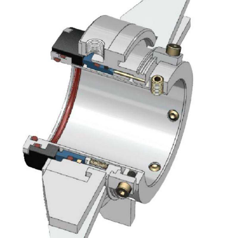
Cartridge seals consist of a pre-mounted mechanical seal on a shaft sleeve that can be installed as a whole over the shaft or shaft sleeve. Cartridge seals are very easy to install and the chance of short service life due to suboptimal installation is less probable. It should come as no surprise that cartridge seals are a lot more expensive than the previously discussed seals. On the other hand, there are lower maintenance costs. Incidentally, it is not always possible to apply a cartridge seal if, for example, there is no space in the house.

An end face mechanical seal is a device intended to prevent or minimize leakage from a vessel through the clearance around a rotating shaft entering that vessel. Perhaps the most common example is the end face mechanical seal used in the water pump of an automobile engine. Most pumps used in petroleum refineries, chemical plant and pipelines also use end face mechanical seals.
The simplest possible mechanical end face seal consists of a shoulder on a rotating shaft which rubs against a stationary case. This concept is shown in Figure 3.
As with packing or any bearing material, lubrication and cooling are required to prevent heat buildup and wear. Hydraulic pressure tends to force fluid between the faces and provide a lubricating film but the face separation must be kept very small to minimize leakage. Cooling is provided by the surrounding liquid. The conceptual design shown in Figure 3 is very simple, but it demonstrates the basic principle of the end face mechanical seals. Of course, it has functional drawbacks which must be addressed.
Seal face leakage is governed by many variables, but the dominant variable is face separation. A variation of a few micro-inches (millionths of an inch) in the face separation can cause significant changes in leakage. Unfortunately, shaft movement can amount to several thousandths of an inch.
A practical approach to overcoming shaft movement is to mount one of the seal faces in a flexible manner so that it can move axially. Obviously a desirable feature, this flexibility is a prerequisite for effective seal design.
Figure 4 shows an improved seal as compared to Figure 3. In Figure 4, The sealing shoulder on the shaft has been removed and replaced with a component which is not permanently attached to the shaft. This component is called the primary ring. The “face” of the primary ring rubs against the mating ring. Since the primary ring and the shaft are two separate parts, an additional sealing device must be used to prevent leakage between the shaft and primary ring. The flexibly mounted primary ring can compensate for the small variations in movement on the axial plane. It can also adjust for seal face wear. Figure 4 is a very simple mechanical seal but it illustrates the concept used by the majority of mechanical seals. Of course, some additional components are required to preload the faces, transmit torque and provide ease of installation.
Figure 5 shows a more complete mechanical seal including a replaceable mating ring, “O-ring” gaskets, springs, setscrews and various other hardware. As will be seen later, the design of these components may vary considerably according to the required service for the seal. In addition, the assembled components themselves may be arranged and oriented in various ways to accomplish varying degrees of sealing, reliability and redundancy.
In a mechanical seal, the primary leakage path is between the seal faces. Naturally, increasing the face separation increases the leakage. In fact, as will be shown later, doubling the face separation can increase the leakage rate by a factor of eight! This relationship between leakage and face separation provides a powerful incentive for minimizing face separation. In modern mechanical seals, face separations are so small (on the order of a few microns) that the leakage rate is affected by the surface roughness. The effective face separation is a combination of the surface roughness of the two mating parts and the fluid film thickness. This concept is illustrated in Figure 6. The seal manufacturer can control the initial surface finish by lapping and polishing. A typical seal face is flat to within 23 millionths of an inch. This degree of flatness is so small that refracted light rays must be used to measure it. The fluid film is established during initial start-up of the seal by hydraulic forces.
The principle of establishing a fluid film is essential to all seal designs. Most mechanical seals are designed to operate in liquids; these seals require a liquid film. Designing a seal to operate on a gas film is much more complex. Whether the film is gas or liquid, it reduces the gross contact between the rotating component and the stationary component. It also provides lubrication to reduce friction and wear. Without a stable fluid film, gross rubbing contact could damage the faces.
Mechanical seals may be classified by their design features and the arrangement of those features. The Design category includes the details and features incorporated into a single primary ring/mating ring pair. The Arrangement category includes the orientation and combination of the primary ring/mating ring pair. Figure 7 illustrates the classification of mechanical seals.
The Design classification considers the details which enter into the features of these components. Some examples of these features are balance, face treatment, rotating element, springs, secondary sealing elements and drive mechanism. In general, these design features are not completely independent; that is, emphasis of a particular feature may also influence other features. For example, selection of a particular secondary sealing element may influence the shape of the primary ring.
By definition, the primary ring is the flexible member of the mechanical seal. The design of the primary ring must allow for minimizing distortion and maximizing heat transfer while considering the secondary sealing element, drive mechanism, spring and ease of assembly. Many primary rings contain the seal face diameters, although this is not a requirement of the primary ring. The primary ring always contains the balance diameter.
Balance. The term “balance” is frequently referred to as the relationship of hydraulic forces on a seal but it is actually a geometric ratio. Balance ratio is defined as the ratio of the hydraulic closing area to the hydraulic opening area. This ratio is customarily expressed in a percentage.
Figure 8 illustrates the concept of balance. In a seal, hydraulic pressure acts on the back of the primary ring; the resulting force pushes the faces together. This force is called the closing force and this area the closing area. Similarly, any pressure between the seal faces creates an opening force which tends to separate the faces. Therefore, the face area is also called the opening area. The balance ratio is simply the ratio of the closing area to the opening area.
As shown in Figure 8, the area above the seal face outside diameter is disregarded when the closing area is computed. This area is not considered because the pressure is the same all around it; consequently the contribution of the resultant of the hydraulic forces on this area is zero.
When the closing area is reduced, the closing force is reduced proportionally; this feature can be used to advantage when designing a seal. However, for a seal shape such as shown in Figure 8, the closing area will always be greater than the opening area. In order to make the closing area less than the opening area, the shape can be changed as shown in Figure 9.
The seal shown in Figure 8 is said to be an “unbalanced” seal. Its balance ratio is greater than 100% because of the necessary clearance underneath the mating ring. Typical balance ratios for unbalanced seals range from 120 to 150%. The seal shown in Figure 9 is said to be a “balanced” seal; its balance ratio is less than 100%. The balance ratio of “balanced” seals is typically from 65% to 90%.
The distinction between “balanced” seals and “unbalanced” seals is simply that balanced seals have a balance ratio less than 100%. A seal with 99% balance ratio is balanced, a seal with 101% balance ratio is unbalanced.
For a given pressure, balanced seals have less face load than unbalanced seals. Therefore, balanced seals are normally used in higher pressures than unbalanced seals.
Primary ring shape.The shape of the primary ring may vary considerably according to the incorporation of various design features. In fact, the shape of the primary ring is often the most distinct identifying characteristic of a seal. Figure 10 shows four examples of typical primary ring shapes.
Figure 10a represents a primary ring associated with elastomeric bellows seals. This primary ring has been optimized to take advantage of the elastomeric bellows and a large, single spring.
Figure 10b represents a primary ring with an inserted seal face. Insert faces must be designed with care because temperature differentials can cause differential expansion between the adaptor and the primary ring. Insert designs can also have problems associated with mechanical stress and distortion.
Figure 10c and 10d show how the shape of the primary ring is influenced by the secondary sealing element. Figure 10c is a primary ring designed to work with a wedge. Figure 10d is designed to work with an O-ring. Also, Figure 10c shows an unbalanced shape while Figure 10d is a balanced shape.
Face Treatment.The most common seal face design is a plain, flat surface but there are many special treatments designed for specific applications. Figure 11 shows some of the more common face treatments. The plain, flat face is most common. In general, face treatments are a means of modifying the pressure distribution between the seal faces. The most common objective is to increase the opening force and thereby reduce the magnitude of the mechanical contact. Face treatments may be considered to produce hydrostatic or hydrodynamic forces.
Rotating Element. Although most illustrations have shown the primary ring to be rotating with the shaft, either the primary ring or the mating ring may be used as the rotating element. Seals with rotating primary rings are said to be “rotating” seals; seals with stationary primary rings are said to be “stationary” seals. Because the springs are always associated with the primary rings, sometimes the distinction is made as “rotating springs” versus “stationary springs”.
For convenience, rotating seals are used in most equipment. Pump shafts are already made of a comparatively high grade material and manufactured to close tolerances. This makes pump shafts well suited for rotating seal applications. Assembly of rotating seals can generally be done directly on the shaft or by using a relatively simple sleeves. Figures 5, 8 and 9 all show rotating seals with stationary mating rings.
Stationary seals have some advantages over rotating seals. In small, mass produced seals for modest services, the entire seal may be placed in a package which minimizes shaft and housing requirements for the equipment. Figure 13 shows a low cost stationary seal. Stationary seals are also used to advantage in large sizes or at high rotational speeds. Above 5,000 to 6,000 fpm, a rotating primary ring (which is flexible, by definition) may require dynamic balancing (for rotational imbalance) in order to operate in a stable mode. A stationary primary ring does not require this balancing. On the other hand, the stationary seal does require a close bore tolerance. This close bore tolerance is usually a second manufacturing operation on most equipment. Stationary seals sometimes incorporate special design features such as auxiliary liners, sleeves or adapters to help retain the mechanical advantages of the seal. Figure 14 shows a stationary metal bellows seal used in high temperature centrifugal pumps.
By definition, the mating ring is the non-flexible member of the mechanical seal. The design of the mating ring must allow for minimizing distortion and maximizing heat transfer while considering ease of assembly and the static secondary sealing element. The mating ring can contain the seal face diameters, although this is not a requirement of the mating ring. To minimize primary ring motion, the mating ring must be mounted solidly and should form a perpendicular plane for the primary ring to run against. Figure 15 shows some typical mating rings.
Floating. Figure 15d is the floating ring type. This design offers the flexibility of using teflon, grafoil, or an O-ring (Figure 15c) for the secondary sealing item. If teflon or grafoil is used, a pin should be added to prevent rotation due to the low coefficient of friction of these materials.
The secondary sealing elements are gaskets which provide sealing between the primary ring and shaft (or housing) and the mating ring and shaft (or housing). They are called secondary sealing elements because their leakage path should be secondary to the seal face leakage. Loading by hydraulics or mechanical force makes the secondary seal tight in its confined area. The secondary sealing element for the mating ring is always static axially (although it may be rotating). Secondary sealing elements for the primary ring are described as being either pusher or non-pusher in the axial direction. The term pusher is applied to secondary seals that must be pushed back and forth by the movement of the shaft or primary ring. A non-pusher secondary seal is a static seal for the primary ring.
Pusher type secondary seals have the disadvantage of damaging the surface to which they must seal. This damage, called fretting, is caused by the cyclic movement of the secondary sealing element as the shaft rotates. In contrast to the pusher design, a non-pusher secondary sealing element could not cause any fretting.
On the other hand, this rubbing and dragging effect is also an advantage of the pusher design because it adds damping and therefore stability to the seal. This damping can make a significant difference in performance for some services.
Figure 16 shows examples of pusher, non-pusher and static secondary seals. The pusher design may use O-rings, wedges, etc. The non-pusher is always some sort of bellows with a static section. Mating rings use various static gasketing and O-ring designs.
Bellows. Figure 16a is a full convolution elastomeric bellows. It offers the greatest possible flexibility to the front section of the primary ring. The front section of this bellows has minimum contact with the shaft or sleeve, thus minimizing wear and hang-up. The large tail section provides a considerable sealing area to compensate for imperfections in the shaft. There are also are variations of the full convolution design that use a half convolution. Its ability to accept axial motion is reduced, due to the one-half convolution design.
Figure 16b is a bellows made out of teflon or glass-filled teflon combinations. This seal which is designed for the extremes of corrosive environments, provides the advantages of the non- contacting bellows convolution. Because it is made out of teflon, support rings or a drive collar is required to attach the tail section or the bellows to the shaft. Due to the requirements of flexibility, the convolutions must be considerably larger in cross-section than the typical elastomeric bellows design.
Figure 16c is an all-metal bellows style seal. It has the inherent advantage of flexibility associated with bellows design for high temperature applications. Due to its all-metal construction, it offers considerable freedom of design since it is not restricted to the temperature and chemical limits of elastomers. Metal bellows are constructed of individually welded metal leaves approximately .004/.012 thick. A large number of leaves are required to provide the maximum amount of flexibility associated with other styles of bellows seals. The mechanical closing force that is provided by the spring on other seal designs is accomplished by stressing the bellows from free height in this design. Metal bellows seals are inherently balanced because of the manner in which the bellows becomes distorted when pressurized.
“V” Rings, “U” Cups and Wedges. Figure 16d is a wedge. Wedges are typically made of TFE material. They are considerably more flexible than the “V” ring or U-cup arrangement because they operate on the ball-and socket principal. Special manufacturing fits are not a requirement for wedges because of the shallow angle of contact between the primary ring and the shaft. However, it does require a polished surface for effective sealing (32 rms with polish).
In addition to wedges, there are U cups and V rings. Their construction as a secondary seal offers limited amounts of flexibility and requires extremely close tolerances on the cross-section fits. The “V” rings are generally manufactured in TFE or TFE-filled material, requiring pre-loading of the rings to activate the point contact on the lips. Because of the “V” ring design, it can be used at high pressures but it is the least flexible, and most rigid of the secondary seal designs. Because of it’s construction, the “V” ring cannot flex to compensate for motion and it must be pushed along the shaft to take up wear at the seal faces. Shaft and primary ring finish must be highly polished (15 rms) in order for this type of secondary seal to operate leak-free.
O-Rings. Figure 16e is the O-ring. This is by far the simplest and most popular secondary sealing element. It has been used successfully over a wide temperature range and in a variety of fluids. O-rings are considered to be self-energizing seals and do not require much mechanical preloading. This feature allows O-rings to be used at very high pressures. O-rings are offered in a complete range of chemical resistant and general service compounds. Buna-N, Neoprene, Ethylene-Propylene, Viton, and Kalrez are typical materials selected for a variety of service conditions. On the other hand, Teflon does not make a good O-ring material, particularly if the O-ring is to be dynamic.
There are encapsulated O-rings. This is an attempt to obtain the chemical resistance offered by Teflon and the flexibility of the elastomeric O-ring. Unfortunately, the result is dominated by the hardness of the Teflon outer shell. The recommended surface finish of the shaft/sleeve is 15 rms. The encapsulated “O” ring is sensitive to temperature fluctuations. Because of these limitations, encapsulated O-rings are usually recommended only for static sealing.
In every mechanical seal there is always a need for keeping the faces closed in the absence of hydraulic pressure. Generally, a mechanical device in some form of spring is used. Figure 17 shows some of the different types of springs used in mechanical seals.
Single spring.A single spring seal has the advantage of comparatively heavy cross section coil which can withstand a higher degree of corrosion. Another advantage is that single springs do not get clogged by viscous liquids. The disadvantage of a single spring is that it does provide uniform loading characteristics for the faces. Also, centrifugal forces may tend to unwind the coils. Single springs also tend to require more axial space and a specific spring size is required for each seal size.
Multiple springs.Multiple springs are usually smaller than single springs and provide a more uniform load at the faces. The same spring size can be used with many seal sizes by simply changing the number of springs that are used. Multiple springs resist unwinding from centrifugal force to a much higher degree than a single coil spring since the forces act differently. The most obvious disadvantage of small springs is the small cross section wire. This makes the smaller springs subject to corrosion and clogging.
Wave spring. The next form of spring generally considered is the wave type, simple described as a washer into which waves have been formed to provide a given amount of mechanical loading . The main reason for using this type of spring is that it requires even less axial space than the multiple spring design. On the other hand, special tooling must be made for best manufacturing results. Further, the tempering required on this design limits materials to those which are not as corrosion resistant as the high grade stainless and Hastelloy groups. Also, when using wave springs, a greater change in loading for a given deflection must be tolerated. That is, a great deal of force loss or force gain, with comparatively small axial movement must be expected.
Metal bellows. A metal bellows is actually a combination of a spring and secondary sealing element. Welded edge metal bellows resemble a series of Belleville washers. Formed bellows may be used to reduce the quantity of welding; however, a formed bellows has a much higher spring rate than a welded bellows. The bellows thickness must be selected for resistance to pressure without an excessive spring rate. The welding technique and bellows shape must be selected for maximum fatigue life.
The term “hardware” is used to describe the various devices which hold the other components together in the desired relationship. For example, a retainer might be used to package the primary ring, secondary sealing element and springs into a single unit. Another example of hardware is the drive mechanism which is necessary to prevent axial and rotational slippage of the seal on the shaft.
A drive mechanism is required because of the torque created between the seal faces. Both static and dynamic drives are required. The static drive is only required to hold an axial position and transmit torque. The dynamic drive must transmit torque and allow for the axial flexibility of the primary ring. Figure 18 shows some variations of drive mechanisms. Dedicated devices made of strong materials are said to be positive drives and are generally preferred in the heavy duty seals.
Key drive.This is one of the more rugged forms of drive. In high pressure, comparatively large size units, the ruggedness of this type of drive is in keeping with the balance of the sturdy features incorporated in seals for high pressure applications.
Elastomer Drive.This is not a positive drive method and is generally limited to light duty seals; however, it is extremely simple, economical and effective for some services.
Spring drive.Another effective drive mechanism for light duty seals is to incorporate the drive into the springs. Care must be taken in this design as to the direction of rotation, corrosion rate and spring rate.
Although all end face mechanical seals must contain the five elements described above, those functional elements may be arranged or oriented in many different ways. Several dimensional and functional standards exist, such as API Standard 682 – Shaft Sealing Systems for Centrifugal and Rotary Pumps, which describes the configurations for used in Oil & Gas applications. Even though the scope of API 682 is somewhat limited, it may be extended to describe end face mechanical seals in general.
Configuration refers to the number and orientation of the components in the end face mechanical seal assembly. For example, springs may be rotating or stationary. Single or multiple pairs of sealing faces may be used. For multiple seals, the individual pairs of sealing faces may be similarly oriented or opposed. Containment devices such as bushings may or may not be used as part of the configuration.
Single seals. The vast majority of all seals fall into the single seal category. In this category the seal can be mounted so that it is inside the process liquid or outside the process liquid. Inside mounted seals are easier to cool and generally can seal higher pressures. Also the direction of leakage is opposed by centrifugal force. Inside mounted is by far the most popular, see Figure 19.
An outside seal is shown in Figure 20. Outside seals have minimal contact with the process liquid. This is an advantage in sealing corrosive liquids providing that overheating is not a problem. A disadvantage of outside seals is that the direction of leakage is the same as centrifugal force.
Multiple seals. Multiple seal arrangements can provide environmental controls and/or redundancy. The most common types of multiple seal arrangements were previously called double and tandem but are called Arrangement 2 and Arrangement 3 by API 682. The double seal emphasizes environmental controls while the tandem seal emphasizes redundancy.
The principal purpose of the tandem seal is to provide redundancy. The two seals are oriented so that the outer seal can accomplish the sealing task if the inner seal fails. A tandem arrangement is shown in Figure 21. Because of this redundancy, the outer seal is sometimes called the “backup” or “safety” seal. Tandem seals use a buffer fluid to lubricate and cool the outer seal. The inner seal operates in the process liquid and is cooled by that liquid. Any leakage from the inner seal must be contained by the outer seal and buffer system. The buffer fluid is normally at a pressure less than the stuffing box pressure. In order to keep the buffer pressure low, the buffer system is vented continuously.
Tandem seals (API Arrangement 2) are also used in “stages” (perhaps this is the origin of the name “tandem”) when process pressures are extremely high. When tandems are used in stages, the buffer system is pressurized to some intermediate pressure, typically half the stuffing box pressure.
The double seal (API Arrangement 3) uses two primary ring/mating ring pairs oriented so that a pressurized barrier liquid is maintained between them as shownin Figure 22. On double seals, the inner seal seals between the process liquid and the barrier liquid. Because the barrier system is at a greater pressure, any leakage is barrier liquid. The outer seal seals between the barrier liquid and the atmosphere. In most cases the barrier liquid is circulated and cooled to prevent heat buildup.
Notice that Figure 21 and 22 are identical. The only differences are the design of the faces and balance diameter and these details are not shown. This is somewhat controversial and many would describe both Figure 21 and 22 as being “tandem” because of the orientation of the components. Traditionally, a “double” seal would have the primary rings in a back-to-back orientation; however, for purposes of operation, either face-to-back (shown) or back-to-back may be used.
The biggest problem with the double seals is maintaining the barrier liquid at a higher pressure than the stuffing box. It is generally recommended that a 20 psi or 10% differential in favor of the barrier be maintained at all times.
In the past, double seals were described as primary ring/mating ring pairs which faced in opposite directions. A classic double seal is shown in Figure 24. This is usually true but is not a requirement of the double seal arrangement. Similarly, a tandem arrangement was frequently described as seal pairs facing the same direction, see Figure 21. Again, this is not a requirement. In a tandem arrangement, the buffer fluid is at the lower pressure and is continuously contaminated by leakage of the product across the primary seal. In a double seal arrangement, the barrier fluid is at the higher pressure and the product fluid is continuously contaminated by leakage of the barrier fluid across the primary seal.
Double seals (API Arrangement 3) are used with API Piping Plans 53A, 53B, 53C or 54. Tandem seals (API Arrangement 2) are used with API Piping Plans 52and 55.
The term “adaptive hardware” is applied to hardware designed to simplify the incorporation of the primary ring and mating ring into the equipment which requires the mechanical seal. The most common examples of adaptive hardware are the sleeve and gland.
When the components are pre-assembled onto a sleeve and gland plate, the complete assembly is called a cartridge seal. This complete assembly can be easily slid onto the shaft and bolted in place thus reducing the potential for installation errors. Some cartridge seals use regular component seal parts whereas other cartridge seals might use specific purpose parts. API 682 specifies that only cartridge seals are acceptable to the standard.
Figure 23a shows the plain integral type gland plate which, if lapped on the sealing surface and gasketed perfectly to the face of the box without distortion, can serve as a sealing face against the rotating seal head. It is an item utilized on many compressor installations, showing that when applied correctly, even a gas such as Freon can adequately be sealed with this type of design. It becomes a desirable feature, especially where axial room is at a premium. It must be considered only where practical. If a relatively large bolt circle in relation to the shaft size is inherent in the unit, this design may prove uneconomical.
Figure 23b is a plain end plate with a pressed-in seat element. Some seal manufacturers advocate this design and it can be utilized where its stresses, replacement features and economics can be tolerated.
Still another auxiliary feature is termed the quench type gland plate. This gland type incorporates an entrance for liquid behind the seal face on the atmosphere side. Two other desirable features are to be gained from this quench gland-one is the safety provided by the throttling effect on the escaping liquid if the seal fails; the other relates to toxic liquids. If the liquid handled is toxic-instead of using the quench gland with a secondary liquid, the liquid can be vented to a safe area.
Sleeves are employed as an adapter from the seal requirements to the shaft requirements of the equipment. For example, the seal may require different diameters, as in a balanced seal. Figure 24 shows the two most common types of shaft sleeve.
Figure 24b is the “cartridge” or “package” sleeve. This design allows the complete seal, gland and sleeve to be assembled before it is installed in the pump.
Mechanical seal pumps provided by The Titus Company provide many benefits over traditional magnetic drive pumps, particularly in industries working with slightly dirty liquids. These pumps are ideal for moving liquids contaminated by suspended particles. The liquids going through CDR Pompe pumps should be low viscosity and clean or only slightly dirty. You’re likely to find them in industries that complete chemical processes, such as pharmaceuticals, wastewater treatment and fertilizer production.
The CCL-B Series uses a standard motor and close-couple execution to function properly. One distinction is the Plastic Lined Horizontal Single Stage Centrifugal Pump, which can complete both closed- and long-coupled processes.
The lined shaft sleeve uses a mechanical CSE seal design to prevent the metallic parts of the sleeve from coming into contact with any fluids in the pump. While it generally uses the standard PP lining in these models, it also accommodates other materials, like Hastelloy C.
Another benefit of this separation is that you can feel more secure about the connection and seal created between the two. You have to push the lined shaft sleeve into position manually. As you do, the sleeve will push the O-ring against your impeller, providing a tight seal that lasts even if the pump itself fails. And, once fitted, the sleeve will synchronize with the shaft and the impeller, keeping all parts together even when the pump rotates in the opposite direction.
The seal chamber keeps solid particles and slurry from contacting the seal, which can affect the pump’s efficiency. This chamber is wide and conical to ensure the entire seal is protected. It can handle all venting, flushing and draining operations.
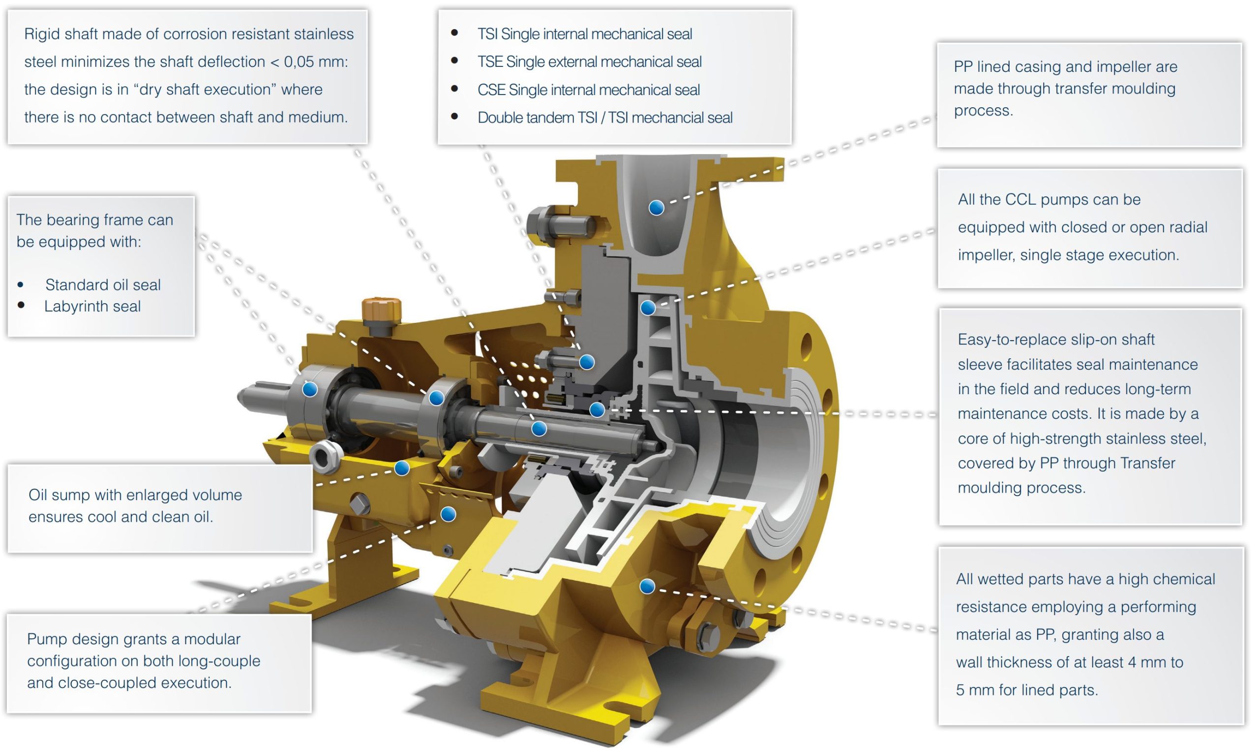
Ensuring you have the proper seal for whatever fluids you’re pumping is essential to prevent dangerous leaks and optimize productivity. For example, clean fluid requires a TSI single internal seal, while corrosive fluids prefer a TSE single external seal. Dirty and aggressive fluids need a CSE single internal seal. For the most dangerous fluids, you will need a double tandem seal for the best chance against leakage.
TSI/TSI Double Tandem Mechanical Seal: For PLAN 53A/54. Ideal in situations where the media is dirty, unstable and unable to be released into the air.
CSE-Q Single Internal Mechanical Seal With Quench: For PLAN 62, when necessary (after liquid crystallization). Provides options for working with corrosive, abrasive, dirty liquids. It has one of the simplest maintenance needs due to a semi-cartridge construction.
Made with 400 series stainless steel, this shaft offers no leakage points and less than .05 mm shaft deflation. A long screw provides balance and rigidity as it connects the shaft to the impeller. Both the materials and its construction ensure the shaft will have a long, reliable life free of corrosion while improving the seal’s life.
The key-driven system for their Transfer Molding impeller eliminates the common start-up reverse rotation error and lets your pump get right to work. The sold metal configuration provides high chemical resistance, and the back vanes are ideal for the life span of the impeller, seal and bearing.
The models in this series also utilize polypropylene-lined mechanical seals, as well as Polyvinylidene fluoride (PVDF) and Perfluoroalkoxy (PFA) lining. Because you have more options, you can cater these machines more specifically to your needs. Specifications include:
Transfer Molding took this sold metal impeller and made it even more durable and chemical-resistant by adding Fluopolymers lining consisting of PP, PFA and PVDF – a collection of sturdy polymers that avoid chemical reactions while enhancing the impeller’s reliability mechanically. Using a system that’s key-driven, you no longer have to think about reverse rotations on startup. And thick back vanes aid the bearings and seal, providing all parts with a longer life span.
Choose a seal chamber lined with your preference of material – you can choose between PFA, PP or PVDF. All seals use a broad, conical build that’s equipped with breaking ribs. All chambers are made to push slurry and solids out of the seal’s way, as they can interrupt the media flow.
With the seal’s conical design, it can fit nearly any mechanical seal type, including both CSS single seals and CDC double cartridge seals. By providing a wide range of operations, you can procure maximum flexibility for any operation, even in challenging conditions. You can also adapt it to fir a number of UCL pumps.
Conventional Double Seal – Cylindrical Seal Chamber External Flushed – ISO 12756 –EX DIN 24960: Works similar to the CDC Double Cartridge Seal, with the necessary strength to prevent hazardous materials from leaking into the surrounding atmosphere and the ability to pump abrasive and dirty media.
Single External Seal Tapered Seal Chamber: Suits PLAN 02. This seal comes in a variety of materials by many brands, so you can use whichever you’re most comfortable with. The model version includes single PTFE bellow seals, which work best as external mountings.
CDC Double Cartridge Seal Tapered Seal Chamber: Good for PLAN 53A-54. This seal is one of the strongest available, designed for operations where leakage is immediately dangerous, such as with toxic or flammable materials. Because it doesn’t need the media to lubricate it, it’s also a good choice for working with unstable, dirty and polymerizing media.
Double Cartridge Seal Tapered Seal Chamber:Ideal for PLAN 52-53-54. It works similarly to the conventional double seal, but with the better maintenance of the cartridge configuration.
Faces Sealed in Diamond SiC: An immensely durable diamond coating provides a longer service life with practically no wear. It also contributes significantly to energy-saving costs.
CSS Single Internal Seal Tapered Seal Chamber: Works will for PLAN 62, as it’s also available in CSS-Q. A semi-cartridge configuration makes maintenance a breeze, even after working with corrosive and moderately dirty media. The metal and media parts never come in contact with one another so it’s also resistant to abrasive materials.
This shaft is made from 400 series stainless steel, molded into a strong, rigid shaft that should provide less than .05 mm deflection of the shaft, providing a long, reliable seal life free of corrosion. The shaft is manufactured to ensure there are no weak points that could result in leakage of hazardous materials. It comes with a long screw that allows it to easily connect with the impeller.
This part is separated from the impeller, allowing for an easier replacement when the need arises. It also constrains the damage to only the sleeve so the impeller does not need to be replaced along with it. In the case where failure occurs, the pump should still maintain a secure seal, as the sleeve pushes the O-ring into the impeller and cannot be adjusted without removing the sleeve.
The shaft sleeve is essential in creating a proper seal in the pump, and with the push-in-position design of this sleeve, you can feel confident in the manual security of the pump. Any part that could touch the media is coated with PFA and SiC to prevent corrosion, but you can easily change the material if you prefer a different lining, like Hastelloy C. Should the pump move in the wrong rotation direction on starting, the sleeve synchronizes with the impeller and shaft, preventing the seal from loosening.
You can use two different types of seal protection for this bearing bracket – the standard oil seal, or a non-contacting labyrinth seal. The latter option provides a constant level oiler and conditions monitoring if you so choose.


 8613371530291