
mechanical seal failure analysis made in china
Mechanical seals have been widely used in petrochemicals and other industrial sectors because of their good sealing properties and long service life. However, accidents often occur if mechanical seals are improperly installed and poorly maintained. Mechanical seals were not as good Packing seals are welcome. Because mechanical seals are relatively precise components, correct installation procedures, strict operating rules, and reasonable maintenance systems are powerful measures to ensure the performance and normal operation of mechanical seals. For this reason, large countries Sealing companies have sealing technology training centers to guide users on how to use mechanical seals properly. There are also several well-known sealing scholars in China who often hold workshops on sealing technology to promote the correct use of mechanical seals.
1. Take out the mechanical seal to be installed from the packing box and place it on a clean surface, protect the sealing surface, and arrange all labels and certificates for inspection;
2. Check the type, specification and material certification of the mechanical seal, the number of parts, whether the matching of the dynamic and static rings meet the requirements of the drawing, and whether the parts have the manufacturer"s identification mark;
3. Check the surface quality of each part, especially the seal and end faces of the dynamic and static rings for any scratches and scratches. If they are damaged, they must be repaired or replaced. The surface of the parts must be clean. Apply a layer of oil;
5. The mechanical seal of the parallel spring transmission, pay special attention to the rotation direction of the spring. The rotation direction should be the same as the rotation direction of the shaft. Looking at the direction, a clockwise rotation is required for a right-handed spring and a counterclockwise direction is required for a left-handed spring.
6.For the host installed with mechanical seals, check the axial string, radial runout, related perpendicularity, concentricity, surface roughness, mating dimensions, and requirements for the pump coupling according to technical requirements.
(1) Amount of axial string: not more than 0.1mm, generally between 0.025 ~ 0.1mm, the axial string is too large, making the specific pressure of the mechanical seal spring unstable, causing excessive wear or leakage of the seal end face. The vibration of the seal will damage the seal, which is more obvious in the graphite ring. In addition, because the axial crosstalk is too large, it will also cause local corrosion, erosion or wear of the contact between the mechanical seal and the shaft (or sleeve). The polytetrafluoroethylene sealing ring is more affected because it is less elastic than the rubber sealing ring. Therefore, the axial string amount is changed from the original requirement of ± 0.5mm to no more than 0.1mm, which can reduce the excessive amount of axial string.
(1) First install the anti-rotation pin 1 into the pin hole of the seal gland. Regardless of the vertical or horizontal anti-rotation pin press fitting, pay attention to the depth buried in the manhole, so that the length of the pin extension does not match the static The bottom of the groove of the ring (static ring seat) may touch the shaft surface [see 9-6 (a), (b)].
(2) Set the static ring sealing ring 2 on the static ring 3, and align the groove on the static ring with the anti-rotation pin 1 in the gland 10, and push it evenly into the gland.
(2) Put 6 sets of moving ring seals inside the moving ring 7, and then put the pressure ring 8 on the moving ring. Note that the pressure ring should press the seal ring 6.
(3) Put the pressure ring, moving ring seal ring and moving ring together into the spring seat 4, pay attention to the groove on the outer diameter of the moving ring should be aligned with the protruding part of the spring seat.
(4) Put the spring praise seat together with the spring, pressure ring, moving ring seal ring and moving ring on the shaft marking position, and then use the fixing screw 9 to fix the rotating part on the shaft.
The removal order of the mechanical seal is opposite to the installation order. It is strictly forbidden to knock with an iron during removal. It is best to use a special removal tool to remove it in order. If there is dirt or condensation on the sealing element, clean the dirt before removing it.
1. Comprehensively check whether the mechanical seals and auxiliary devices and pipelines, valves, and instruments are installed properly. The pipelines must be cleaned to prevent blockages. This is particularly important for new devices. Impurities often enter the seals from the pipelines and affect the sealing performance. The system should be evacuated to prevent the formation of air plugs in the height of the sealed cavity, leading to dry friction operation.
2. Perform a static pressure test before starting. The test pressure is the same as the working pressure. Check the mechanical seal itself and the relevant seal points and joints for leaks. If there is a leak, try to deal with it.
1. Before the host is started, the sealed chamber should be filled with liquid or sealed medium. If there is a separate auxiliary sealing system, it should be started first, and the cooling water system must also start to circulate (last stop when stopping). For transporting solidified medium or viscosity For large media, the sealed cavity is heated by applying steam to melt the media. It must be cranked before starting to prevent the soft ring from bursting due to sudden start.
2. Perform normal cutting operation before normal use, and observe whether the temperature rise of the sealing part is normal. If the light emblem leaks, you can run for a period of time to make the end surface fit more evenly, until the leakage children gradually reduce to normal. If the leakage does not decrease within 1 to 3 hours, you need to stop and check.
3. Boosting and heating operation: Mechanical seals that have been tested under normal pressure operation should do the same boosting and heating operation as the operating conditions in time. Boosting and heating can be performed separately. The process of lifting should be slow, pay attention to boosting (or warming up) ) Possible changes in the process, such as whether there is a collision of the parts, whether the end faces are disengaged, whether the frictional heating is too fast, whether the anti-pin is disengaged or damaged, whether the pressure is stable (required that the pressure fluctuation is not greater than ± 0.1MPa), and If there is any leakage at the seal ring and the seal end face, if everything is normal, it can be put into production.
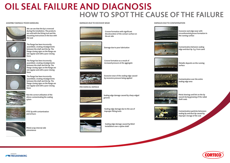
The failure phenomena of mechanical seals are: end face wear, seal ring thermal cracking, deformation, corrosion, elastic loss or breakage, and damage to auxiliary seals.
Some people abroad have statistically analyzed the failures of three hundred sets of mechanical seals in five years. The results are shown in Table 9-4.
Domestic Qilu Petrochemical Company refinery applies domestic type 104 and 110 type mechanical seals to 274 pumps after applying a cycle (10 months) for statistical analysis of mechanical seal failure rates and failure causes. 9-7.
1. The total failure rate of both hot oil and low viscosity oil is 74.3%, which indicates that the sealing of hot oil and low viscosity medium is still the main subject of current research in refineries. In addition, high viscosity media is not good for sealing.
2. Friction pairs are the most common failure points in mechanical seals, accounting for 62%. The failure phenomenon is represented by friction pair wear and relative rotation of the tungsten carbide ring and the moving ring seat, both of which account for 53.1% of the total number of failures. Statistics on the failure of 300 sets of mechanical seals in five years are very close.
3. The cause of failure is not only related to the mechanical seal itself, but also to the working conditions and auxiliary devices. No flushing is one of the main reasons for the failure of the mechanical seal.
Accompanying the leak, there will also be seal heating, smoke, vibration, sound, power increase and other phenomena. Because there are many factors that cause leakage, specific failures should be analyzed in detail. And measures.
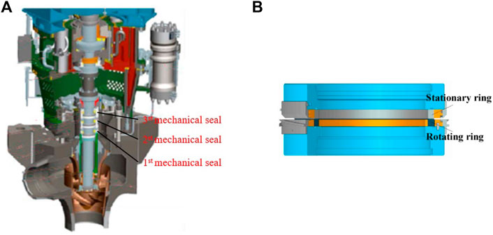
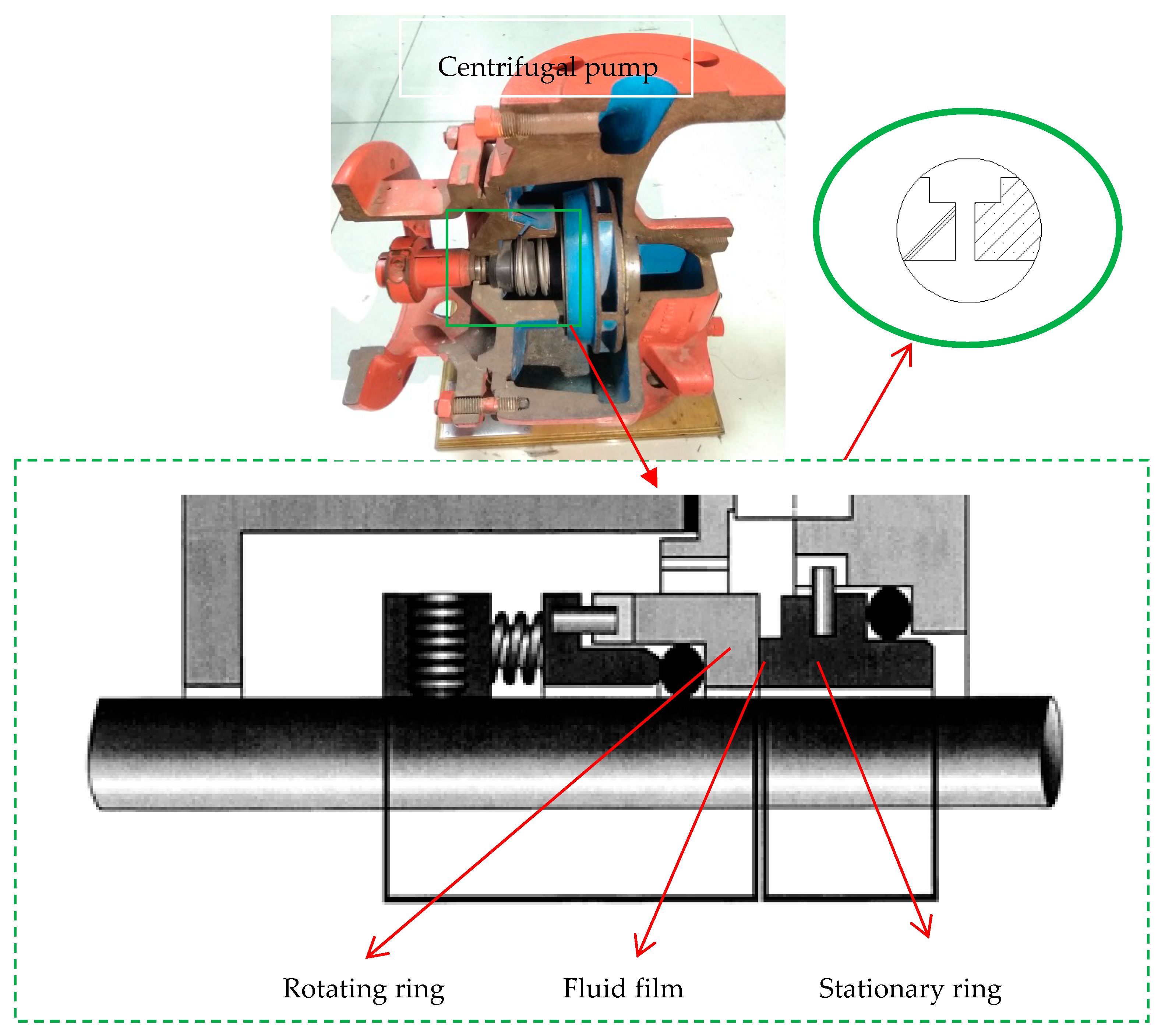
1. A mechanical seal face and a mechanical seal ring of the automotive pump mechanical seal. It is ideal to combine a carbon mating ring with a ceramic or sic seal face for the combination has the small abrasion,good thermal conductivity and mechanical strength and no corrosion to each other.A liquid film existing between the mechanical seal face and the mating ring can work as a lubrication no matter what kind of materials are combined. The spring load and the fluid pressure are joined together to seal the interface between them. Too large a specific pressure of the seal faces will not do good to the fluid film so that the heat will increase or the seal face and the mating ring wear each other too earlier. If the specific pressure/closing force is too low the interface will increase so that a big leakage will occur.The statistics of the failure of automotive pump mechanical seals shows that 80%-95% failure is caused by the friction of the seal faces and mating faces. The precision of the seal faces,the choice of the seal face materials, the end-face specific pressure can decide the working time of the automotive pump seals concerning the seal construction, the springs and fluid pressure.
2. The installation of automotive pump mechanical seals is here referred to as not only the installation of the mechanical seal but also the installation of the mechanical seals and the other parts of pumps. While the automotive pump mechanical seals are assembled each part of the mechanical seal should be kept clean and non-destructive.If the mechanical seal surface has some defects the seal will leak.
3. Pump shaft axial distortion.A certain specific pressure on the seal face and the mating seal face can make the mechanical seal work so the pump shaft cannot distort axially too largely.The axial force which the pump impeller produces while rotating will destruct the sealing of the mechanical seal and sometimes the mechanical seal face and the mating face will depart so that the leakage will take place. it is vital to control the axial distortion of the pump shaft and the axial interface between the pump shaft and the bearing should not be larger than 0.13mm. The axial balance design is very important.
4. The large vibration of an automotive pump mechanical seal.The automotive pump mechanical seal vibrates too largely and the seal face and the mating ring will not seal the fluids.The large vibration lies in the other parts of pumps, for example,the bad pump design, the bad work of the parts and the precision of the shafts.
5. The pump shaft deflection is too large. The pressure on the end seal faces will be not the same if the pump shaft deflects too largely. try to reduce the cantilever length of the pump shaft and make an option of the right material for the shaft.
6. The steam or vapour. At the entrance of the pump the steam corrosion will occur if the device system is not good. A good number of bubbleswill occur when the steam happens in the cooling water, which will shock the outside surface of the seal ring and the mating ring to be damaged and make the fluid film not form a sustainable flowing film and the seal ring and the mating ring will friction in a dry way and in the end the seals will not work properly
7. The precision of mechanical process is not tight. The deficiency of the precision is here referred to as not only the precision of the mechanical seal but also the precision of the other parts of the pump including the impeller,pump body and belt wheel and etc.
By examining a failed seal and its application, subsequent failures can be avoided. In semiconductor applications, seal failure can be caused by anything from loss of compression set to chemical degradation and plasma erosion.
Trelleborg Sealing Solutions supports customers with the analysis of the cause of failure and provides recommendations on more suitable materials or improved designs to reduce downtime and increase productivity.

The sealing rings are one of the most important components as the sealing devices in the wet clutch unit of a heavy vehicle. The sealing ring, made from PTFE composites, was subjected to serious wear on the sealing surface, but the mating metal surface only had slight abrasion. A specialized test rig was designed for wear research and failure analysis of the sealing ring. The composition analyses of the ring material, working conditions and wear surface characteristics by visual inspection and tribological properties as well as microscopic analysis with scanning electron microscope was performed to determine the wear mechanism and failure causes. Results revealed that the wear of PTFE composites was characterized by abrasion and adhesion after a certain duration testing, and the wear mechanism changed to thermal fatigue and abrasive wear in the stage of intense wear. The thermal deformation and fatigue were primarily responsible for the rapid wear of the PTFE composites for the sealing rings.
J F Zhou, B Q Gu. Effect of End Face Deformation on the Characteristic of Fluid Film in Mechanical Seal[J]. Lubr. Eng., 2006, 31: 81–84Author information

Cause: Common in dynamic applications, abrasion occurs from repetitive contact between the O-ring surface and the housing resulting in excessive friction between the two. Improper lubrication or surface finish of the metalwork can exacerbate the risk, as can ingress of abrasive contaminants into the sealing system.
Solution: Ensuring the correct lubrication for the sealing system is important, PPE can offer a range of O-ring sealing materials with improved abrasion resistance. Our engineers can also advise on the correct surface finish for the metalwork. Ingress of contaminants can be reduced through the use of wiper or scraper rings.
Solution: Correct elastomer material selection is vital to ensure the seal is compatible with the application media. Chemical attack is accelerated at elevated temperatures and when elastomer seals are under stress, as a result of, for example, excessive stretch or squeeze, and mechanical conditions. PPE engineers can recommend the most appropriate sealing material based on your application parameters. For the ultimate in chemical resistance combined with high temperature capability, ask about our Perlast® perfluorolastomers (FFKM). Check the chemical compatibility of the main elastomer material types using our online guide.
Cause: Swell is caused by the ingress of media into the elastomer, as the result of a chemical similarity between the compound and the media. The increased seal volume can lead to gland fill, extrusion and loss of sealing. Chemical swell can also result in a loss of physical properties such as tensile strength.
Solution: Switch to an elastomer sealing material with proven resistance against the chemical environment. PPE sealing experts can help you identify a material which will deliver lasting sealing performance in the chemical media within your application. Check the chemical compatibility of the main elastomer material types using our online guide.
Cause: Physical and chemical changes can occur to an elastomer at elevated temperatures that result in set. Cross-link density can increase, this results in the O-ring losing its elasticity and ability to return back to the original shape, this is a permanent chemical change. Stresses introduced to the seals at elevated temperatures can be unable to relax when the temperature is reduced, this is often referred to as cold set, this type of set is reversible upon heating. The reduction in cross section results in a lower contact sealing force, which increases the risk of leakage in systems where thermal and pressure cycling occurs. Other causes include improper gland design, volume swell due to system fluid and incomplete curing of the seal during production.
Solution: Selecting elastomer materials with low compression set and/or higher temperature capability will help to extend seal life. Gland design should also be checked to ensure the O-ring is not over-compressed with too much squeeze applied. Cold set can be reduced by using a more flexible polymer structure, this would be reflected in a lower glass transition temperature.
Cause: High stresses, usually as a result of high pressures, forces the material into the clearance gap, this process is typically called extrusion. Pulses of high pressure can cause the clearance gap between the mating edges to open and close. This can lead to the O-ring becoming trapped between the sharp edges of the mating surfaces, resulting in physical damage to the seal surface often referred to as nibbling.
Solution: A harder seal material can help, as can the use of backup devices to effectively reduce clearance gaps. Your PPE sealing expert can also advise on the installation of correctly sized O-rings and back up devices for your application, decreasing your clearance gaps and minimizing the risk of extrusion and nibbling.
Cause: When elastomer seals are exposed to high-pressure gas at elevated temperatures for a prolonged period of time the gas absorbs into the polymer compound. When the external pressure is reduced, the gas dissolved within the material comes out of solution to form micro bubbles. As the gas expands, it will permeate out of the material. Failure occurs if the rate of decompression and expansion is high, and the trapped gas within the seal expands beyond the materials ability to contain the gas bubbles.
Solution: Increasing the time for decompression and reducing the temperature will typically reduce the risk of explosive decompression (ED) damage, as will choosing an ED-resistant material. PPE has been an industry leader in the development of ED-resistant elastomer seals and O-rings – conforming to NACE TM0187, TOTAL GS EP PVV 142 Appendix 8, NORSOK M710 Annex B and ISO 23936-2 Annex B international standards, and improving operational safety and efficiency.
Cause: Installation damage can take a wide range of forms, from ‘skiving’ of the seal with metal components through to damage caused by careless installation of dirty, twisted or improperly lubricated seals. Incorrect sizing of the seal for the application is also a significant factor in installation damage.
Solution: With long term exposure to plasma, seal damage is unavoidable. The chemical compatibility of the material can help to resist damage for longer, improving the lifetime of the seal and reducing the impact of equipment downtime. Ask your PPE sealing expert about Perlast®, Nanofluor® and Kimura® materials which provide plasma resistance that is comparable or superior to many high purity FFKM grades.
Solution: A harder O-ring material is a good starting point for the prevention of spiralling. You might also consider a different seal profile, with PPE X-rings (quad rings) and D-seals proven to resist spiralling without a reduction in seal performance. If a high pressure seal is required, the T-seal provides a robust sealing solution with complimentary backup rings. X-rings, D-seals and T-seals can usually fit existing O-ring grooves/glands.
Cause: The temperature of the application has exceeded the maximum temperature ceiling of the selected seal material or excessive temperature cycling has occurred. High temperatures can increase the cross-link density in elastomers resulting in an increase in hardness and modulus, making them less elastic.
Solution: Selection of a higher temperature elastomer material is the obvious solution. PPE can provide reliable high temperature sealing up to +325°C (+617°F) with its range of Perlast® perfluoroelastomers (FFKM).
Solution: Groove/gland design should be optimised such that there is sufficient space to accommodate the additional seal volume at high temperatures and avoid ‘gland fill’ - see our online groove/hardware dimensions guide.
Cause: Ultraviolet light exposure on an elastomer material can have a destructive effect. UV light has short wavelength, therefore it has high energy, which can interact with the molecular structure of the exposed side of the elastomer. This generally results in cleavage of the polymer chains and causes cracking on the surface, which will lead to leaking and premature failure.

If the lip has worn out then this is often caused by the seal not being sufficiently lubricated before installation causing abnormally high temperature, the presence of foreign matter, disproportionate internal pressure or an excessively rough shaft surface. Similarly if when removing a seal, if the lip has hardened and there are visible cracks, you can be sure that this has again been caused by abnormally high temperatures, excessive internal pressure or insufficient lubrication. The cause for the abnormally high wear has occurred due to friction as the amount of lubricant was below the specified level and therefore did not reach the seal lip. Alternatively, insufficient lubrication can come from dry-wear conditions because the vehicle’s oil levels are low. Another sign of this is if the lip wear band is smooth and glossy.
Alternatively, if the lip has softened, then the main cause of this is the lip having the incorrect material required for the application. In order to prevent this from reoccurring make sure the correct seal is sourced for the specific application before installation.
If you notice the lip of the seal has worn unevenly then this is due to cocked seal installation or an excessive shaft offset. As before, both should be checked during installation but crucially before the vehicle is out on the road.
Installation errors tend to be a big factor in automotive parts failing prematurely. This is apparent if you can see that the lip of the seal is scratched, caused by improper assembly, improper handling, an incorrect shaft chamber or the presence of foreign matter entering the seal. The scratches are often caused by being assembled over burrs or other defects in the shaft chamber, the lip coming into contact with sharp metal parts during transit or storage or if the seal was handled with gloves contaminated with metal particles.
As stated improper handling can be a factor in causing a seal to fail prematurely, the tell-tale sign is the seal lip being swollen or soft. The swelling is caused by the lip being soaked in solvents or petrol before installation. Alternatively, if when removing a seal you see the fit trace is disconnected locally then the seal could have been deformed because of an improperly designed assembly jig or a gap in the press-fit occurred due to rough handling.
However, although problems during fitting can contribute to the part failing, other issues may be the key factor. If the lip’s waist (flex area) is broken, then this can be because of improper assembly but can also triggered by excessive internal pressure. Similarly if the lip is turned-under, the lip edge is severely worn and the wear band is concave then this is connected to an incorrect shaft chamber, improper assembly and excessive internal pressure meaning the oil seal area exceeded the maximum pressure it was originally designed for. To prevent this reoccurring, identify the maximum pressure for the seal and check it is compatible with the vehicle. However, if the lip edge is severely worn but there are circumferential grooves on the wear band then the cause is that the shaft finish was rougher than the specified range again this can be prevented by sourcing the correct part for the specific application.
Similarly, if the lip edge is severely worn and there are grooves or indentations on the surface. Foreign matter can affect the seal in many ways whether the cause is due to a shaft or seal that has been contaminated with foreign particles being used or the contaminants were embedded in the seal lip. The cause can be triggered when the seal is assembled in the presence of dirt and/or dust causing the contaminants to become embedded in the sealing lip. In addition, if the seal or the housing was assembled with silicone, the sealant will have contaminated the shaft or seal.
If, when removing a seal the garter spring has become disconnected then this has likely been caused by an incorrect shaft chamber or improper assembly, checking the installation can ensure you and you customers are happy with the finished job.
However, if there isn’t an obvious fault with the oil seal, the cause is often difficult to diagnose, but before you prematurely condemn a good seal first check if the shaft is scratched or the diameter is incorrect, if the shaft rotational direction does not match the helix on the seal, there is excessive shaft offset or runout, the shaft is worn or the seal has been installed incorrectly.
Like with the lip leakage diagnosis if the oil seal is problem free, check if there is a scratched or an improperly sized bore or excessive bore surface roughness. Similarly if the seal OD is damaged or chafed the bore is often the cause. Ensure you check if there is an improper sized bore diameter, incorrect shaft chamber or improper assembly jig before installation.


 8613371530291