
mechanical seal failure analysis price

To improve the performance of any piece of equipment requires a complete understanding of its operation and the effect on its component parts. The definition of mechanical reliability is the probability that a component, device or system will perform its prescribed service without failure for a given time when operated correctly in a specified environment.
A component part is the smallest part that would normally be replaced. A device, such as a pump, compressor, agitator, mixer, etc., is made up of many component parts. A system, such as a process plant, refinery, power plant, ship, etc. is made up of many devices. Thus, when a critical component fails, it can have a tremendous economic impact, not only on the device in which it is installed, but on an entire system. A mechanical seal is just such a component. The major causes for seal failure on a pump are a result of the following conditions:
As the shaft of a pump begins to rotate, a small fluid film develops between the seal faces along with unwanted frictional heat from the seal surfaces in sliding contact. If the amount of frictional heat developed at the seal faces cannot be removed, then the liquid being sealed will flash to a gas or begin to carbonize. Developed frictional heat at the seal faces must be removed.
Each contacting seal has an operating envelope, as illustrated in Fig. 1. The upper limit is determined by wear. More importantly, a seal must operate at a temperature to prevent boiling of the liquid sealed. Operation within the envelope will result in excellent seal life.
Common cryogenic fluids such as argon, nitrogen and oxygen are stored near their atmospheric pressure and pumped near their normal boiling points. These are the most common cryogenic fluids used in industry. The fluids are delivered by over-the-road trucks to industrial users and hospitals. Each truck uses a single stage centrifugal pump driven by a hydraulic motor to move these liquids from the truck to the storage tanks. One fleet operator with 25 trucks began an aggressive program to reduce failures and improve equipment reliability. An analysis of the operation’s seal life and repair costs is shown in Table I. Not only were the maintenance costs excessive, there were also financial losses when deliveries could not be made.
Upon reviewing the seals that failed in this cryogenic service, it became clear that at certain times during the operation of the pump the fluid at the seal faces was flashing and extreme wear and heat checking occurred on the mating ring in the seal assembly. Further complicating the problem was the cool-down period for the equipment. Both the pump and piping had to be cooled down to the liquid gas temperature. Any rise in product temperature could have led to the pump cavitating and the seal running dry.
To be successful in operating near the boiling point of the fluid being sealed requires a seal that eliminates the frictional heat from the sliding services in contact. A seal that is in a controlled environment will allow the liquid to turn to a gas without violent flashing. The properties of the cryogenic fluids to be sealed are given in Table II.
The success from using a non-contacting seal can be explained by reviewing the vapor pressure curve for nitrogen shown in Fig. 2. In this case, nitrogen that is being transported by tank truck is normally at 30 psig/2bar and -320 F/-190 C. When using a contacting seal, the temperature increase at the seal faces is sufficient to start the boiling process at pumping pressure. In an uncontrolled environment such as a contacting seal, continuous flashing damages the seal faces, shortening seal life. During operation of the non-contacting seal design, the temperature rise at the seal faces is only a few degrees, eliminating violent flashing of the cryogenic liquid.
The savings associated with improved seal reliability for the 25 trucks in this cryogenic delivery fleet operation are shown in Table I. These savings were substantial enough to allow the purchase of a new tank truck.
A poor mechanical environment requires a seal to move an abnormal amount during operation. The motion transmitted to a seal can be angular or axial. The most common cause of angular motion is piping stresses transferred to the pump casing. This type of loading will result in premature seal failure.
In one case, a power plant experienced a seal failure every three months. Measurements taken on the pump casing at full operating pressure and temperature indicated 0.016” of deflection. This, in turn, distorted the seal chamber and mating face.
The estimated angular distortion or out-of-squareness at the seal face was greater than 0.012”. The shaft was turning at 1800 RPM. This meant that the seal had to flex 0.012” of travel 1800 times/per minute.
The solution to this problem was to add an expansion joint in the piping in the suction line to the pump, which would eliminate the high load being transferred to the pump casing. Clearly, this failure had nothing to do with the design of the component parts of the seal. The savings per year per pump were estimated to be $18,000.
Axial motion from thermal growth of equipment can cause the seal to run solid, resulting in failure. This is more likely to occur on large pieces of equipment. High thrust bearing wear might be expected on a high-speed boiler feed pump, where, over time, it could lead to seal failure.
A ship’s power plant, with low boiler demands, is a prime example of where axial shaft motion might occur. The greater the wear on the thrust bearing, the more axial travel the seal must handle. When the travel is excessive, the seal will run solid and fail. The cost to the ship’s power plant would be excessive.
A synthetic fuel processing plant implemented a program to reduce maintenance costs and improve the reliability of two large compressors vital to plant operation. The gas compressors can reach process temperatures of 650 F and 370 psia respectively. Steam is used as a buffer fluid to prevent gas in the compressor from reaching atmosphere. Steam pressure is 10 psi above the process gas pressure. At these conditions, steam cutting of the existing sealing surfaces was occurring. Annual maintenance to replace the existing seal was $25,000. Annual bearing repair was $12,500. The annual cost of steam was $100,000.
Review of existing non-contact seal technology determined that it could be redesigned to handle high temperatures. Both compressors were converted to the new technology. Each compressor subsequently operated successfully for 10 years without any major work required. The $2,470,000 in savings over this time period reflected a significant payback from implementation of dry-gas sealing technology for high temperature services. The first compressor will be overhauled this year and the second compressor next year.
As shown by these short case study examples, substantial savings can be achieved by analyzing the reasons for short equipment life and applying the best solution. By the same token, improper specification, application and maintenance of critical components like mechanical seals can lead to reduced reliability and substantial losses for an operation. MT
James P. (Jim) Netzel is an engineering consultant based in Yorkville, IL. His 40+ years of experience in the design and application of mechanical seals includes 20 years of service as chief engineer at John Crane, in Morton Grove, IL. During his career, Netzel has authored (and presented) numerous technical papers through the International Pump Symposium, STLE, ASME, BHRA, AISE, SAE and various trade publications. He also has written chapters on seals and sealing systems for The Pump Handbook, The Centrifugal Pump Handbook and The Compressor Handbook. This article is based on a presentation delivered at MARTS 2008. E-mail: jpnetzel@comcast.net
2. Netzel, J.P., Redpath, D., and Wallace, N.M., 2001, “Toward Reduced Pump Operating Costs – Part 2 Avoiding Premature Failures,” 18th International Pump Users Symposium, Texas A&M, Houston, TX
by Umeet BhachuWeibull analysis is an important statistical tool in the realm of reliability engineering. It helps in the modeling of increasing, decreasing and constant failure rates.
In maintenance organizations where time and cost of repair are crucial elements, it is of paramount importance for a reliability engineer to determine swiftly and accurately the failure modes and root causes underlying a particular issue to avoid further machinery breakdowns. This translates into cost savings because a pro-active approach, rather than a reactive maintenance attitude, forms a basis for implementing advanced programs, such as reliability centered maintenance (RCM), in the operating organization.
It is prudent, however, to assess the data (in our case time between failure) for randomness and distribution prior to performing such an analysis. Data following a renewal process is independent and identically distributed (iid), which means the data arises from a single population. If the failure data does not follow a renewal process, the Weibull analysis leads to incorrect predictions about the nature of machine reliability. This often causes inappropriate action on the part of maintenance, resulting in costly and unwarranted repairs. Improving or degrading trends in reliability leads to failure data that does not follow a renewal process. There are various methods, both graphical and analytical, to assess this data before inputting it for a Weibull analysis. We will use one such method called the Laplace trend test.
Consider the case of an API 610-compliant centrifugal pump, one of the most common and critical pieces of rotating machinery in a refinery. Mechanical seal failures are often the initial reason such pumps are brought down for maintenance or repair. Usually, this is not because of an incorrect seal design selection or a faulty seal, but simply because of the way the mechanical seal is operated. Mechanical seals are one of the weakest links in pumps and turbomachines. They fail due to vibration, misalignment, changes in process conditions, incorrect settings on the seal flush plans and various other reasons. Weibull analysis, when properly used in this context, helps the reliability engineer determine and qualify the failure mode without having to stop the machine or wait for the next failure to happen. By using the past failure and maintenance history of the machine logged in the plant’s computerized maintenance management system (CMMS) to calculate Weibull parameters, such as the shape parameter Beta (ß), Weibull can help in determining why the failure occurs.
As a related case, consider a charge pump in a hydrocarbon service, pumping volatile gas oil as the finished product. The pump has a pressurized dual mechanical seal with an API Plan 02/53B. The normal pumping temperature is 85 degrees C, with a maximum temperature of 120 degrees C. The seal experienced multiple failures in the past that have subsequently caused the unit to shut down for seal replacement on both the inboard and outboard ends of this critical pump. Thorough scans of the CMMS system revealed various work order (W/O) and seal failure histories that helped in determining the time to failure (TTF) during each event. TTF provides the input for analysis that will then help to understand and draw meaningful conclusions on why the seal is failing.
We first use the Laplace trend test to determine if the data is suitable for Weibull analysis. Detailed information on computing and using Laplace testing can be found in the various references provided at the end of this article.
When the score is greater than +1.96 or less then -1.96, we are 95 percent confident that there is a statistically significant upward or downward trend. This disqualifies the data from being iid and coming from Weibull analysis is an important statistical tool in the realm of reliability engineering. It helps in the modeling of increasing, decreasing and constant failure rates. Reliability Engineering for Maintenance reliability engineering Re Analysis of a dec/jan14 a single population, leading to a non-qualification from further analysis using Weibull.
However, in our case, the Laplace score is closer to 0, showing that no discernible upward or downward trend exists and the data is essentially random failures qualifying it for the Weibull analysis. So let us now proceed to performing a Weibull analysis on our failure data.
Weibull distribution can be created for any data and is flexible in modeling a wide range of data. In our example, we use only failure data to model this distribution without incorporating non-failure (also called censored or suspended) data. While the inclusion of suspended data provides a more accurate distribution, we chose to ignore it due to the quality and accuracy of the data from the CMMS. Table 1 shows the filtered data and the time to failure for each of the failure events. The red line item shows seal upgrade from a different seal vendor performed during April 2011.
In reliability engineering, the bathtub curve is used to represent failure rates with passing time. The shape parameter, also called Beta (ß), helps us in understanding if the failure rate is increasing (wear out conditions) where ß>1, constant (random failures) where ß=1, or decreasing (infant mortality) where ß<1.
In Figure 1, prior to the upgrade, and Figure 2, after the upgrade, it is seen that ß is less than 1, pointing to the fact that these seals are failing in the infant mortality zone. It should be noted that we have a small sample size (failures) for both situations. However, it has been observed by Dr. Robert B. Abernethy, a leading expert in Weibull statistics, that the Weibull method works well for performing engineering analysis, even with such small sample sizes.
It is interesting to note that despite the upgrade on the mechanical seal, the failure pattern was not significantly altered. The seal was unable to clear the infant mortality zone successfully. One of the reasons leading to infant mortality in mechanical seals is connected to the incorrect design and application of the seal. When a mechanical seal is incorrectly designed or selected for a given application, there seems to be an increase in the number of failure incidents during the early life of the seal. The Weibull plot helps draw our attention to the fact that careful consideration needs to be implemented when selecting the right seal design for the application.
From Table 2, the reliability of the seal actually dropped further after performing the seal upgrade by the new vendor. This reflects the fact that the upgrade did not have the desired effect on improving seal reliability in this particular application.
Based on the root cause analysis performed on these mechanical seals (both prior and after the upgrade), we have seen them running at higher temperatures and causing face distortion and other issues leading to early failures. The higher running temperatures were attributed to cooling limitations during operation, resulting from the inability of the selected seal flush plan to cool the seal sufficiently in conjunction with the seal design. The initial seal design selected for the pump prior to upgrade was not an effective design, particularly in regards to the seal face orientation for this application. Weibull modeling is a good tool in predicting reliability and determining gross failure modes for many simple and complex engineering and maintenance related equipment breakdowns. The distribution finds prominent use in implementing maintenance strategies in many world-class organizations by quantifying failures. When failures are random (ß=1), a good condition monitoring program coupled with effective preventive maintenance practices help prolong equipment life. When failures are in the infant mortality zone (ß<1), as we have seen with the mechanical seals, then careful attention needs to be given to the design, fabrication, operating procedures etc. And finally, when failures belong to the wear out zone (ß>1), then a decision has to be made to either run the equipment to failure or develop a proper program for maintenance and overhaul of such equipment, which would include availability of spares as required. It is noteworthy that Weibull modeling information also acts as a valuable asset in project engineering by giving the project team important information during design and selection of machinery based on past equipment performance.
This article demonstrates the importance of using a pre-qualification test, such as Laplace, prior to performing a Weibull analysis. Negligence in performing a pre-qualification of the data can lead to incorrect analysis, subsequently causing costly and unwarranted repairs. Plenty of papers dealing with Weibull do not stress the importance of pre-qualification testing of the data before performing analysis. Detailed root cause analysis should have been the key focus after the initial failures on the first seal. However, in the absence of this approach, the second seal upgrade was also found ineffective due to potential incorrect seal/elastomer design and selection, consequently resulting in repeated failures in a short span. The second upgraded seal failed again in the infant mortality zone due to the similar reasons that caused the first seal to fail. The Weibull method is not the be-all and end-all solution to maintenance reliability problems. However, it is but one tool, and an important tool, in complementing other analysis and empirical methods used to troubleshoot and proactively ensure a higher uptime for the plant.

When a mechanical seal fails in one of your operation’s vital pieces of equipment, figuring out the cause of the failure is often even more important than procuring a replacement seal. After all, if there is an underlying issue causing your seals to fail, replacing the seal is only going to be a temporary fix. Unless you plan on purchasing and installing new seals on a regular basis – something that can quickly become both expensive and time-consuming – figuring out the cause of your seal failures is an essential objective.
This is where mechanical seal failure diagnostic services can prove highly valuable. By simply examining your broken seal, we at Gaddis Mechanical Seals are able to pinpoint the exact cause of its failure, enabling you to perform whatever repairs are necessary to keep the same issue from happening again in the future.
At Gaddis Mechanical Seals, we strive to make our seal failure diagnostic services as convenient as possible for our valued customers. All you have to do is send us your broken seal along with any available information regarding where the seal was located and the events leading up to its failure. From there, our expert team will perform a wide range of diagnostics to determine the exact cause behind the seal’s failure.
This includes inspecting the seal’s O-rings, face, springs, gasket, and every other component. By determining the exact component within the seal that failed and analyzing the design of the equipment that it came from, we are able to provide our customers with an accurate and detailed description of exactly what needs to be fixed in order to prevent the same issue from happening again.

Mechanical seals prevent pumps from leaking by containing the pressure of the pumping process and withstanding the friction caused by the rotating shaft. The right seals provide reliable operation, less wasted product, more cost savings, and fewer housekeeping issues. However, why do mechanical seals fail?
In many pump systems, a mechanical seal is the first component to fail. They are also the most common cause of pump downtime and account for more pump repair costs than any other part of a pump. Often, however, the seal is not to blame. Other culprits include:Bearing wear
Therefore, teams must install and maintain seals properly to prevent failures. Teams must pinpoint the root causes of each failure. But how do plant and maintenance managers isolate the root cause though?
One option is to have a seal manufacturer perform a seal failure analysis. Some seal manufacturers offer complimentary seal analysis on any seal, not just theirs.
End users simply send their mechanical seal to the manufacturer’s engineering team. If multiple seals need to be analyzed, they may come on-site to perform the root cause analysis. Most reviews canbe completedin about two weeks.
With a seal failure analysis, experts deliver a complete diagnosis of why the mechanical seal failed and what actions to take to prevent future failures. The experts who examine the seal can ensure that the ideal seal for the application has been selected. If not, they recommend alternate technologies.
After an analysis, the manufacturing ream will also help end users optimize their system conditions and achieve the best possible operation from their assets. Optimizing mechanical seal performance also improves shutdown to shutdown processes. This information, along with alternative proposals as needed, help end users prevent further failures and improve their return on investment.
Many problems with a system may be discovered by investigating a failed mechanical seal. In most instances, a seal problem is not the reason for the failure. Something else happened to cause it.
The story of what the seal experienced during operation, before it failed, can be revealed by investigating the failure. An analysis may determine or confirm:If misalignment or other mechanical problems exist in the pump system
Eliminating the problems identified by the seal failure analysis may have a huge impact on the system. Several improvements may be realized, including:Optimized operating conditions
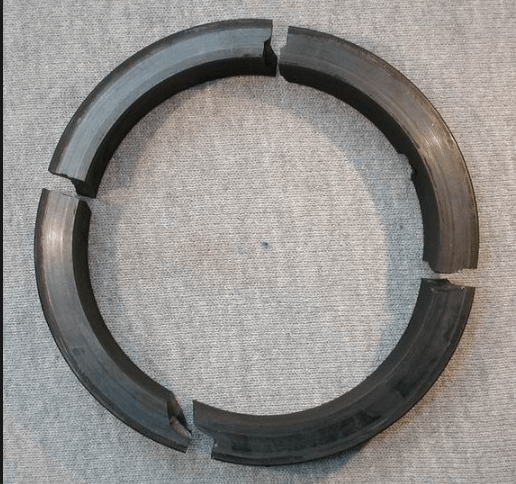
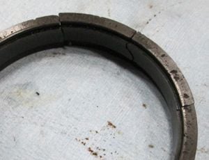
For instance, a stationary seal face is cracked, originating from the drive pin slot. Also, sticky residue has adhered to the face. This crack means something different than a stationary seal face with a crack located at a different position and product residue that is fairly clean and not tacky.
Both cases look the same on a simple table listing all the seal damage. However, the failure cause is different. In the first example, the crack was caused by the product attempting to stick the rotary and stationary faces together. This adhesion caused increased torque on the stationary pin. This caused the stationary face to crack.
In the second example, the crack was likely caused by impact. This indicated that the seal was not installed properly. Different symptom combinations reveal multiple failure modes.
In conclusion, to determine the true reason that a seal failed, seal failure analysis is required. Without a diagnosis of the system problem, failure will continue.
Jack Ferguson is a seal reliability engineer with Sealing Equipment Products Co. Inc. (SEPCO). He is a recent graduate of Clemson University with a degree in mechanical engineering. Ferguson may be reached at jackf@sepco.com.
Fluid Sealing International offers Mechanical Seal Analysis (MSA) service. As a seal is disassembled all parts are inspected to determine their condition with respect to original specifications. It is during the MSA procedure that a failure mode can be identified and recommendations can be determined. These may include changes required in equipment operation, suggested environmental controls for improved performance, upgrades in seal materials, or even a change in seal design.
After a complete inspection of the seal, all major parts are cleaned and replaced. Where necessary, Fluid Sealing International can provide Mechanical Seal Repair Services to repair your seal.

SEAL FAILURE ANALYSIS RESULTS The overwhelming reason for a pump to enter the shop is because of failure of the mechanical seal or packing, yet very few companies are regularly troubleshooting these seals. Ten to fifteen minutes spent at this critical juncture can mean doubling or tripling the life of the seal going into service now.
It is not difficult to determine the cause of failure in 80% of the applications common in industry today. Any company buying mechanical seals from a reliable vendor has the right to expect a sensible failure analysis on the majority of their seal failures. The seal rep is seldom at the shop when the pump comes in for repair, but the folks changing the seals can do a very good job of identifying the reason for failure: steps taken at this point can substantially improve the reliability of the application and save the Corporation far more money than the cost of this time invested. Failure to address the problems evident almost certainly dooms the pump to a short service life upon rebuild.
For the purpose of this report, I will not discuss packing failures but will focus on the major causes of seal failure. The following data is compiled from the records kept at two chemical plants on seals I have personally inspected. The totals expressed represent totals for the plant over a two year history and are not application specific. In most cases, the seals were reviewed after the pump was already back in service, but using the form included in this report has allowed these clients to increase the life of the seals used and has increased the Mean Time Between Failure (MTBF) dramatically over the past two years. CLIENT ONE: a large plant with relatively simple processes and over 600 pumps. This plant has a large powerhouse which it can use for co-generation purposes as well as to supply steam needed for processes in-house.
This client uses a wide variety of seal designs and materials of construction. These designs are component seals, split seals, cartridge seals (single and double/tandem). CLIENT TWO: a medium sized plant that two years ago standardized on cartridge seal designs. This plant does not have a large powerhouse, but runs significantly more involved pump/seal applications (evaporation/condensing/reaction loops/etc.) which lead to other concerns.
RESULTS There is a great deal that can be gleaned from these two plants experience. The largest contributing failure in each case was I.D./O.D. rubbing of the rotary seal member against some object, most commonly the bore of the stuffing box. There have been numerous studies completed and documented that clearly prove the value of large bore stuffing box/seal chambers for mechanical seals. The two plants listed have instituted on-going upgrades for their pump populations; if a seal comes out and shows rubbing as the cause of failure, they immediately return to the previous work order on this particular pump. If that failure report also states rubbing as cause of failure, the stuffing box is replaced with a seal chamber on the spot, prior to seal replacement. The concept of “Shaft Deflection Ratio” has been discussed at length in previous issues of this magazine and countless others devoted to our industries. The stiffer the shaft ratio, the better the pump is able to perform off its Best Efficiency Point (BEP).
A good rule of thumb is that a ratio value less than 60 will guarantee seal life is increased dramatically in “Off BEP” operating conditions. Remember that your pump operates where its pump curve crosses the system curve: systems age and change over time ( a gate valve is replaced with a globe valve, long horizontal runs of piping build up solids, etc.). Pumps purchased for design conditions that don’t match those given the pump vendor EXACTLY can become headaches for maintenance and operations from Day One. The second greatest cause of seal failures was related to o-ring failure. The proper o-ring for an application must address both the fluid being dealt with AND any fluid used to clean the system. VITON might be the proper material for the normal application: what if your system is cleaned every shut down with a caustic steam solution?
You lose the seal a week later and the failure analysis states o-ring failure; is the connection made between the caustic steam washout and the failure of VITON? You are far better off stipulating more expensive o-rings which can survive both conditions than losing seals after your turn-around, when the plant and system are up and have to run. Please also note the drop in seal failures due to poor installation when comparing Plant One and Plant Two. With the decrease in maintenance budgets and personnel, the increasing utilization of “multi-craft” people demands simpler seal designs for installation by off-shift personnel. Component seals can be very difficult to install and are sensitive to dimensional information often unknown and/or unavailable to “back-shift” employees. “The road to Hell is paved with good intentions”; if your plant has downsized in the maintenance department ( and whose plant hasn’t?) cartridge designs may justify their additional cost because of their ease of installation. Don’t blame an electrician for shortened seal life when complicated seals are being installed!
Note also the frequency that bearing problems cause seal problems; the two are inextricably intertwined. Lip seals were designed around the time of the Second World War; they were designed for automotive water pumps. They have a limited design life which is far short of bearing design life. Bearings are seldom a failure because of fatigue; far more commonly, they fail from contamination and water emulsions in a pump’s bearing housing.
Upgrade your lip seals every time you change bearings on your pumps and you will see the bearing life triple and quadruple. Upgrade from lip seals to whatever your engineering staff decides is best; labyrinth seals, full face seals, magnetic seals, etc. Which one of us would buy equipment designed in the Forties today for any application in our plants or homes?
Finally, TRAIN YOUR OPERATORS!! They deserve and need training, because they are the people causing the majority of your seal and bearing failures. I have yet to work with a maintenance man who didn’t care about the quality of his work; maintenance people are not the ones wrecking the production equipment. Untrained operators regularly run pumps dry, start them with closed suction or discharge valves, and fail to report increased noise or vibrations from the equipment they run. They don’t do this to sabotage the plant; they do it from ignorance. Production “owns” the equipment: maintenance just “borrows it” when it needs to be repaired.
Stop cursing your maintenance budget and start training your operators: you’ll see how quickly maintenance can become a profit center for your plant instead of “the ugly step-child” it too often is perceived as in the plant budget and planning sessions. CONCLUSIONS Seal failure analysis does not have to be complicated or time consuming. Most of it can be done by your in-house staff in less than ten minutes at the time of failure with reasonable accuracy. Don’t lose the data; gather it on the simple form enclosed, and log it into a simple data retrieval system. Marshall the assets you already have in-house to get a better view of your problem pump applications, make a few simple upgrades on repeat offender pumps, and improve your bottom line today. Plants can readily improve their overall profitability with better training of operators and giving their maintenance people the freedom to make some simple upgrades at the time of seal/bearing failures.
Mechanical seal failures are the most common cause of pump downtime and failure, so mechanical seals and seal support systems must be very carefully designed with components and options selected according to the specific application. However, even high-quality seal support systems can fail unexpectedly for a variety of reasons. When this happens, it’s critical to conduct mechanical seal support failure analysis quickly and accurately, because every minute of downtime results in lost production.
Identifying the failure mode and root cause of a mechanical seal failure allows you to not only correct the immediate problem but prevent it from happening in the future. Thorough mechanical seal support failure analysis can help you understand the conditions under which the seal failed.
In this article, we’ll look at the three most common types of seal support failures—leaks, overheating, and seal failure—what can cause them, and how to prevent them with proactive measures.
Mechanical seals minimize leakage around rotating equipment by creating a “seal” between two very flat surfaces—one stationary and one rotating. These mechanical seal faces inevitably produce some leakage, but the leakage normally evaporates immediately and isn’t a problem. When leaks become noticeable, it’s time to perform mechanical seal support failure analysis to find out why.
When troubleshooting mechanical seal leaks, make note of any unusual noises, damage, or other symptoms accompanying the leak. Use the table below as a starting point to help you identify the cause of the leak.
Overheating indicates either friction between rotating components or excessive fluid temperatures. There are two main reasons mechanical seals overheat: inadequate cooling and excessive friction. Refer to the table below to help diagnose the problem.
As you can see, there is a lot of overlap between the causes of leaks and overheating. Many mechanical seal failure modes can be traced back to the same underlying causes, so be sure to check for leaks as well and use the leak troubleshooting table to investigate.
Excessive heat can eventually lead to heat checking. Mechanical seal heat checking can be identified by fine radial cracks in the seal face caused by excessive stress from the mechanical load and thermal expansion. These cracks may be barely visible to the naked eye, so heat checking can go unnoticed until failure occurs and it’s too late to save the seal. The risk of heat checking increases with high temperatures and high-viscosity fluids like those used in SAGD. It is more common in brittle materials like tungsten carbide.
The same underlying issues that cause leaks and overheating can eventually lead to complete seal failure. A mechanical seal failure likely began as a leak or overheated condition that went unaddressed. The same troubleshooting procedures for leaks and overheating apply, but once the seal has failed, correcting the problem becomes much more difficult. Therefore, it’s important to be proactive and check for problems like leaks and overheating before they cause major problems.
Do you still need help with mechanical seal support failure analysis, or want to learn more about how to be proactive in preventing failures? Field Advisors at Edmonton Valve & Fitting can perform an onsite or remote evaluation to determine the cause of failure and make recommendations on upgrades, component materials, tubing diameters, and instrumentation to help deter mechanical seal failures.
To find out more about how Edmonton Valve & Fitting can help with mechanical seal support failure analysis, contact usthrough our websiteor by calling 780-437-0640.
According to its own analysis, some 98% of mechanical seals fail prematurely before they have reached their optimum design life-time expectancy. The Flowserve Seal Failure Analysis App is a web-based tool designed to visually identify and prevent future mechanical seal failures. Accessible via desktop, tablet and mobile devices, this reference tool is a resource for reliability engineers and maintenance staff, tasked with troubleshooting and preventative maintenance. While mechanical seal failures are the number one cause of pump and mixer down-time, this area represents a great opportunity to reduce whole life costs on site across all pump systems.

Allowing your pump to run dry can be very damaging to a mechanical seal. Under the right conditions, mechanical seals can experience thermal shock and shatter within 30 seconds or less.
VIBRATIONPump vibration is caused by pump imbalance, improper alignment, operating the pump too far to the right or left of the BEP (Best Efficiency Point) on theperformance curve, etc. Vibration hurts your equipment and can result in damaged seals and shortened seal life.
When it comes to pumps, hammers are not friends! Mechanical seal faces can be very fragile. Pounding couplings onto the shaft will damage the mechanical seal.
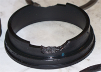
Lack of knowledge and information accounts for the majority of mechanical seal installation errors. Consider normal operating conditions, the potential for off-design excursions, and non-process activities, such as cleaning, steaming, acid and caustic flushes. The picture to the right is an example of poor material choice for an abrasive liquid.
Tom Borrino, Regional Engineer for John Crane, recommends that if you’re interested in reducing seal failures, take a look at all phases of equipment application – how is the sealed equipment specified, installation practices, all the way up to operations. Seals are very repeatable, so if you continue operating the same seal, expect to see the same rate of failure in the same manner. He further recommends thinking about the seal in terms of its total lifetime costs – not so much by its initial cost. Start a reliability program that defines the cost of failure and justify it by increasing the seal’s mean time between failures.
Look to your local seal supplier for help with seal selection, best-operating practices, and seal flush plan recommendations. If you have specific questions, ask us about them! We gladly provide mechanical seal assistance to businesses in Wisconsin and Upper Michigan.

Mechanical seals prevent pumps from leaking by containing the pressure of the pumping process and withstanding the friction caused by the rotating shaft. This results in reliable operation, less wasted product, more cost savings and less cleanup. However, why do mechanical seals fail?
In many pump systems, a mechanical seal is the first component to fail. They are also the most common cause of pump downtime and account for more pump repair costs than any other part of a pump. Often, the seal is not to blame. Other culprits include:
Therefore, it is crucial they are installed and maintained properly to prevent failures. Teams must pinpoint the causes of each failure, but how do plant and maintenance managers isolate the root cause?
One option is to have a seal manufacturer perform a seal failure analysis. Some seal manufacturers perform complimentary seal analysis on any seal, not just theirs.
End users simply send their mechanical seal to the manufacturer’s engineering team. If multiple seals need to be analyzed, they may come on-site to perform the root cause analysis. Most reviews can be completed in about two weeks.
to take to prevent future failures. The experts who examine the seal can ensure the ideal seal for the application has been selected. If not, they will recommend alternate technologies.
The team will also help end users optimize their system conditions and achieve the best possible operation from their assets. Optimizing mechanical seal performance also improves shutdown to shutdown processes. This information, along with alternative proposals as needed, help end users prevent further failures and improve their return on investment (ROI). In summary, a sealing failure analysis:
seal failure. Something else happened to cause it. The story of what the seal experienced during operation before it failed can be revealed. An analysis may determine or confirm:
For instance, a stationary seal face is cracked, originating from the drive pin slot. Also, sticky residue has adhered to the face. This crack means something different than a stationary seal face with a crack located at a different position and product residue that is clean and not tacky.
Both cases would look the same on a simple table listing all the seal damage. However, the failure cause would be different. In the first example, the crack was caused by the product attempting to stick the rotary and stationary faces together. This adhesion caused increased torque on the stationary pin. This caused the stationary face to crack.
In the second example, the crack was likely caused by impact. This indicated the seal was not installed properly. Different symptom combinations reveal multiple failure modes.

Deriving additional value from critical rotating equipment can help a company improve efficiency, reduce operating expenses and extend operating life. Upgrades to components such as bearings, seals, couplings and controls keep rotating equipment operating at peak performance. A mechanical seal retrofit or upgrade is often a cost-effective answer to increasing throughput without the expense of investing in new equipment. Engineered seal retrofits can increase reliability, while reducing planned and unplanned outages that disrupt production and reduce revenue.
Mechanical seals are a component of a piece of rotating equipment. When defining the term “engineered,” look at both the component and the equipment in which it is installed. Currently, the common American National Standards Institute (ANSI) and American Petroleum Institute (API) pumps use standard stock seal designs, which are interchangeable from one manufacturer to another.
For larger, high-pressure, high-speed pumps and other unique pieces of rotating equipment, the seal and the equipment are typically designed for the application and use engineered mechanical seals with non-standard envelop dimensions, components, materials or face lubrication technologies.
Experience indicates that seal-related costs in many plants adhere to the 80/20 rule, meaning that 20 percent of the seals account for 80 percent of the total seal and/or rotating equipment maintenance cost. These so called bad actors are often the result of operational transients or issues that may be expensive to resolve or a result of using a seal that is simply too sensitive for the application.
For mechanical seal operation, it is a truism that “all seals leak.” It is when this leakage becomes excessive that equipment operations are in jeopardy. Failure data from a wide variety of industrial applications demonstrates that most mechanical seals are removed from service prematurely, not because the faces wore out but because damage to one of its components made it leak excessively.
Many failures occur randomly in frequency, which may imply that the seal is too sensitive to whatever event caused the component to fail. In such cases, upgrading the seal technology to make the mechanical seal less sensitive may be more beneficial than trying to avoid the event that caused the failure. Just replacing the damaged parts of a failed seal does little to uncover what caused the seal leakage and how to prevent subsequent problems.
The relationship between increased reliability and the converse effect on life cycle cost is certainly true for all mechanical components in a process system. Especially in the field of mechanical seals, this relationship is relevant since seal faces are inherently sensitive to leakage. The typical film thickness between the faces is a few microns and any significant deviation may exponentially increase the leak rate or damage the materials in a matter of seconds or minutes. Engineered seals may offer a good alternative to decrease the sensitivity of the seal parts to the typical and unusual operating conditions of a pump or any piece of rotating equipment with much improved reliability as a result.
A simple method to justify the cost of an engineered seal solution is by verifying the life cycle cost (LCC) of the seal and its environmental control system. Significant savings and excellent returns on investment (ROIs) can be achieved with engineered seal retrofits and upgrades in addressing the bad actors. The degree of technical risk and capital cost can vary widely depending on the nature of the equipment and the application.
A unique way of looking at seal problems is considering the entire operation, not just the failing component. While most seal companies are satisfied to just change-out a failing seal and leave it at that, a more holistic approach to solving seal problems is to go beyond the mechanical seal and look at the entire system.
Because a leaking seal is usually an indication of an even bigger problem, time should be taken to diagnose the whole application before beginning to reengineer the seal. The equipment in which the seal resides, along with the seal housing and hardware, process conditions and the auxiliary support systems, all affect the seal"s environment. When satisfied that the system as a whole is understood, a solution can be developed that will reduce the sensitivity of the seal to the specific application conditions.
The price of highly-engineered mechanical seals can start at $5,000 and run up to $100,000 per seal. Traditionally, mechanical seals have been treated as disposable items, when in fact they are repairable and improvable, regardless of the original manufacturer.
These highly engineered seals carry a lot of inherent or residual value and should not be treated as a commodity. As with any critical component or piece of equipment, these seals can be reengineered, recycled and transformed much in the same way as a pump or compressor would be remanufactured and reused.
An engineered seal adds value to the rotating equipment. Mechanical seals from any manufacturer can be reengineered to meet performance specifications within the same operating guidelines and with minimal changes to foundations, piping and other connections.
The reengineered seals have the same ‘form, fit and function" as the original seals, along with an enhancement of the redesign transformation process. Two case studies demonstrate the value of engineered seals.
Seal manufacturer engineers successfully upgraded two top-entry reactor seals for a major Gulf Coast chemical plant. In the existing, dual-pressurized seal arrangement, the “hard-on-hard” seal faces were extremely sensitive to lubrication-related damages due to a combination of high pressure (2,400 psi), high temperature (450 degrees F) and slow shaft speed (150 rpm). The seal"s short life span (three to six months) and its erratic leakage behavior caused unscheduled shutdowns and posed serious safety and environmental hazards.
This application was of particular concern because the chemicals in use were highly volatile and highly flammable, and therefore, the leakage problem required a highly engineered solution. Even though the original seals were not manufactured by the seal provider, its engineers knew that using an engineered upgrade approach to improve their reactor seals was possible.
The engineers examined the application from every angle to find the best solution that would extend the life of the seal, achieve a higher degree of reliability and eliminate the potential safety hazard. A proposal was made to retrofit the seal"s internal components with more robust face technology and materials that were not as prone to distress during all phases of the process.
A major gas producer in the Houston area was struggling with the seals on two between-bearing, 10-stage pumps that transport ethane at ambient temperature. Ethane was particularly difficult to seal in this application, as it was pumped at suction pressures above 600 psig and at the high pump shaft speed of 6,000 rpm. Low lubricity and the high vapor pressure of ethane made the lubrication aspect of this application challenging.
On top of these difficult conditions, the pump vintage year dated back to the 1970s when seal chambers were still stuffing boxes or had limited space for a beefy seal. Prediction, detection, containment and disposal of seal leakage were critical since the pumps were vital to the output of the plant and subject to an emission limit of 1,000 parts per million (ppm) as measured by EPA Method 21. The original seals were dual unpressurized equipped with API Plan 76 to dispose the leakage vapors to a flare system.
In Plan 76, a pressure switch at the outlet of a dry running back-up seal detected the onset of seal degradation when the primary, ethane lubricated seal leaked excessively and erratically. The cooling of the primary seal faces was achieved with a simple Plan 11 that connected from the second stage impeller. The lifetime of the original seals was poor, from days to a few months at best. Typical damages were heat cracks and severe wear of the seal faces.
A seal provider"s engineering team was asked to make recommendations to solve the problem and proposed an engineered seal face upgrade approach in combination with a change in the Plan 11. Instead of operating the primary seal faces on seal chamber pressures slightly above suction pressure, the engineers suggested maximizing the pressure in the seal chamber to create more vapor pressure margin. By changing the source connection for the primary seal flush, the mechanical seal would operate close to the discharge pressure of the pump.
A new close-clearance bushing in the bottom of the seal chamber was necessary to minimize the flush flow within acceptable rates. The back-up or safety seal from the original manufacturer as well as Plan 76 were left unchanged, as they appeared to work fine.
Also unique to this case was the limited space in which this solution was provided. The user looked at upgrading his pumps with compressor gas seal technology, which is the modern solution for this type of application, but found that this technology requires much more radial space then an old style API pump provides.
In addition, the initial cost, refurbishment costs and leakage rates of gas seals were much higher making the shrink fit face solution the lowest risk upgrade approach.
An engineered mechanical seal retrofit or upgrade transforms the original seal into a more robust, forgiving and reliable product, which can provide significant financial savings. This is why working with the seal manufacturer to “reengineer” seals and systems, not just replace them, is important.
Rather than treating mechanical seals as commodities and just “tossing them out” when they start to fail, upgrading offers a way to further a company"s investment in its rotating equipment and its components.

Years ago, most pump shafts were sealed using rings of soft packing, compressed by a packing gland, but this type of shaft seal required a fair amount of leakage just to lubricate the packing and keep it cool.
Then came the development of the mechanical seal, which accomplishes the job of restraining product leakage around the pump shaft with two very flat surfaces (one stationary and one rotating). Even though these mechanical seal faces also require some leakage across its faces, this leakage normally evaporates and is not noticeable.
However, because of the delicate components used for this new sealing method, mechanical seal failures are the greatest cause of pump down time. To avoid this, it"s essential to apply the right seal for the desired and appropriate function.
A seal can be exposed to a wide variety of operating conditions—sometimes very different from conditions the seal was intended for—which can cause issues down the line. However, even if your seal is the right one for the job, there can be times when it fails faster than anticipated.


 8613371530291