
api mechanical seal quotation
To keep mechanical seal systems functioning as long as possible, we recommend using standardized seal piping plans. Detailed API seal piping plans ensure minimal seal face wear by maintaining the optimal seal chamber environment.
Since they were first formulated, seal piping plans have been maintained and remodeled by the American Petroleum Institute (API). Current plans are based on API 682 and are sorted numerically. In some cases, designated letters are also used to differentiate between plans.
The API Plan 01 is suited to applications where process fluids could easily thicken or freeze within the piping. Plan 01 permits fluid circulation from the discharge area to the seal chamber.
Pressurized barrier fluid reservoir and circulation tank to ensure media will not leak into atmosphereDesigned to ASME Section VIII, Division 1 standardsAvailable to build to (U) and (UM) stamps, registered with national boardFormation of fluid between seal faces provide a longer seal lifeModular design for various combinations of instruments and componentsAvailable with refill pumps, transmitters, switches and cooling coils
Tank Capacity: 2 Gallon, 3 Gallon, or 5 Gallon in 6" or 8" diameterOperating Pressure: 400 PSI @ 200°FTank Material: 316/316L SCH 40Cooling Coil: 1/2” x 0.065” wall seamless tube; 20’ long 316/316LLevel Gauge: Weld Pad– Size 7, 10 ¼” VisibilityHydrostatic Test Pressure: 525 PSIAllowable Temp: -20° F to 200° FFill Port: 3/4” NPTSeal Connections: 1/2” NPTLevel Switch Connections: 3/4” NPT
Carotek manufactures Seal Pot Pressure Vessel Tanks in our Charlotte facility in Matthews, NC. The seal pots are built toASME Section VIII, Division 1, E2007, 2008a, Addenda and are available with ASME “U” and “UM” code stamps. As a premier industrial seal pot manufacturer, we offer standard and custom built ANSI / API mechanical seal support systems for industrial, chemical, and petrochemical applications. Seal pots provide a protective buffer between the product and the atmosphere, and isolate potential product leaks to the atmosphere. As a safety measure, seal pots perform a vital duty protecting the environment and personnel from the dangers of hazardous materials
Our Seal Pots our fully Made in America and meet all the requirements of ANSI and API specifications. Our modular designs are adaptable and can be combined with cooling coils, level switch/transmitters, pressure switch/transmitters, air coolers, and circulating pumps for a wide variety of applications. They are durable, flexible, and offer reliable performance for your demanding operations. Modular design supports various combinations of instruments and components such as built in refill pumps, transmitters, switches and cooling coils.
Seal Pot ASME Certificate of AuthorizationMade in AmericaQuick QuotesQuick DeliveryExpert application assistanceMillwright qualityTIG and MIG weldedBare Tanks with coil can be shipped next dayAvailable with ASME code stamp
After more than five years of planning, the American Petroleum Institute (API) is preparing to release the 4th edition of API Standard 682 (ISO 21049:2011). The API 682 standard, which dates back to 1994 and is formally known as Shaft Sealing Systems for Centrifugal and Rotary Pumps, offers specifications and best practices for mechanical seals and systems to pump end users.
The standard’s latest edition began to take shape in 2006, when API formed a 4th edition task force to respond to end users’ questions and comments about previous editions. The task force soon realized that major changes, including reorganization and editing, would be necessary. While addressing every aspect of the resulting 4th edition (which is more than 250 pages long) would be impossible, this article summarizes the standard’s main points.
Those who use API 682 should understand the standard’s scope and remember that the standard does not include specifications for equipment outside that scope, such as engineered seals or mixers. Another important but often misunderstood point is that API 682’s figures are illustrative and not normative in their entirety.
For example, one of API 682’s figures shows a fixed throttle bushing combined with a rotating Type A seal, but seal manufacturers do not always have to combine these two components. The standard provides normative details in clauses and tables to help purchasers distinguish between requirements and suggestions.
The 4th edition continues to divide seals into three categories, three types and three arrangements. For all practical purposes, seal manufacturers can combine a seal’s component parts into nearly any orientation or configuration. Each orientation and configuration has advantages and disadvantages with respect to certain applications, performance and system disturbances.
Before the 4th edition, API 682 did not specify a minimum clearance between the inside diameter of a stationary seal part and the outside diameter of a rotating seal part. The 4th edition specifies this minimum clearance—typically the clearance between the sleeve and the mating ring. The specified clearances are representative of standard clearances that end users have used for decades. End users should not consider seal components to be “shaft catchers” to restrict shaft movement. The minimum clearance specified in API 682 also applies only to equipment within the standard’s scope. Equipment outside that scope, such as non-cartridge seals, older pumps, non-API 610 pumps and certain severe services, might benefit from larger clearances.
The new standard also updates the default bushings for the gland plate for the three seal categories. Fixed throttle bushings are now the default for Category 1 only, while floating bushings are the default for Categories 2 and 3.
While the 4th edition features the recommended seal selection procedure from the standard’s first three editions, it adds an alternative selection method in Annex A. Proposed by task force member Michael Goodrich, this alternative method recommends using material data sheet information to select a sealing arrangement.
Plans 66A and 66B are new to the standard, although end users have used them previously in pipeline applications. These plans detect and restrict excessive leakage rates in case of an Arrangement 1 seal failure.
The 4th edition has revised the data sheets in Annex C extensively to make them the same for all seal categories. Only two data sheets are included in the 4th edition—one in metric units and one in U.S. customary units. The new edition also folds Annex J into Annex E.
Previous editions of API 682 required metal plugs and anaerobic sealants when shipping new or repaired cartridges. After much debate, the task force decided that threaded connection points should be protected with plastic plugs for shipment. These plastic plugs should be red and have center tabs that operators can pull easily to distinguish the plugs from metal plugs. Shippers should also attach yellow warning tags to the plugs to indicate that end users need to remove the plugs before operation.
Although tutorial notes are scattered throughout API 682, this edition expands the tutorial section, Annex F, from seven pages to 42 pages. The expanded annex includes illustrative calculations. In particular, users interested in systems such as Plan 53B will find Annex F to be useful.
The 4th edition of API 682 is the product of more than 20 years of discussion, debate, usage and peer review. It includes a strong set of defaults and is by far the best and most logical starting point for mechanical seal and systems use. Equipment operators should take the time to familiarize themselves with API 682 to get the most out of this comprehensive standard.
The Type 2609HTC and Type 3609HTC are dependable API 682 cartridge seals that utilize two impressive design innovations by incorporating high-temperature, corrosion-resistant (HTC) sealing and unique high-temperature, live-loaded (HTL) mating ring technology in dual tandem seal arrangements. This new design vastly enhances seal face stability over conventional designs and can extend your MTBR in many services. These seals have ID and OD pressure capability and can withstand reverse pressurization. The seals come with a pumping ring standard, and the bellows have an all Inconel metallurgy for sealing the harshest high-temperature corrosive fluids. The Type 2609HTC is a dual unpressurized rotating bellows cartridge Type C, Arrangement 2. The Type 3609HTC is a dual pressurized rotating bellows cartridge seal Type C, Arrangement 3. Ideal for hot hydrocarbon refinery services.

Seal support systems are vital to the reliable functioning of the thousands of pumps that keep a refinery running around the clock. When they are properly designed, installed, and maintained, the seal support systems help ensure pump reliability and maximize the pump life by maintaining the optimum seal chamber conditions. In Northern California, pump reliability takes on an added dimension—environmental compliance. Any leakage of hydrocarbons could result in sanctions from the California Division of Occupational Safety and Health (Cal/OSHA) or Bay Area Air Quality Management District (BAAQMD).
If you’re new to API plans, you’ll quickly realize that the range of options available in API seal flush plans reflects the range and complexity of the various pumping processes and conditions across a refinery. Choosing the right API seal flush plan is a critical step in ensuring pump reliability. In my years of experience in working with process engineers and maintenance teams at Northern California refineries, we’ve always achieved better outcomes when I have the opportunity for on-site analysis of pumping processes and can advise them on the latest advancements and configuration options available.
The tables below provide an overview of the three standard categories of API seal flush plans—process side, between seals, and atmospheric. It’s not a comprehensive list of all API plans, but I hope they provide enough information to help you understand the range of options available in each category and take the first steps in matching plans with your specific pumping processes.
Description: Process side API seal flush plans use a single mechanical seal to prevent pump (process) fluid from leaking. In this arrangement, the process fluid is the lubricant. It provides a thin film between the seal faces to reduce friction and absorb heat. In doing this, the pressurized process fluid “leaks” across the seal faces and returns to the process flow.
Recirculates process fluid from pump discharge through a cooler, then to the seal chamber; Preferred for viscous process fluids that could clog seal flush cooler
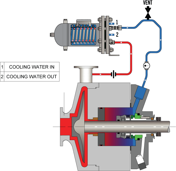
Recirculates process fluid from the seal chamber through a cooler, then back into the seal chamber using a pumping ring; By continually recirculating seal chamber fluid through the seal flush cooler, it provides greater cooling capacity compared to Plan 21
Recirculates process fluid from pump discharge through a cyclone separator, sending clean process fluid to the seal chamber and particulates back to pump suction; For optimum performance, particulates should have a specific gravity twice the process fluid
Delivers clean or cool flush fluid to the seal chamber from an external source; Employs a close-clearance throat bushing to ensure seal chamber higher pressure; Because flush fluid will migrate past the bushing it must be chemically compatible with process fluid
Recirculates process fluid from pump discharge through a cyclone separator, sending clean process fluid to the seal chamber and particulates back to pump suction; Particulates should have a specific gravity twice the process fluid
Each of these API seal flush plans has options to help tailor the plan to the requirements of the specific pumping process. Instrumentation such as temperature, pressure, and flow gauges help monitor system performance. If you’re not using process fluid to lubricate the mechanical seal, flush fluids can be water, water/glycol, or mineral- or synthetic-based hydraulic and lubricating oils. Cooling capacity needs to be carefully calculated based on process fluid temperature, pressure, and mechanical seal type. When you’re faced with choosing among these options, the guidance of an experienced, local seal support system vendor is critical. Well-informed design decisions are the foundation for long-term reliability.
Description: The majority of refinery processes deal with hydrocarbons. In comparison to process side API seal flush plans, between seal plans provide a higher degree of protection against leakage. As a result, between seal plans (or dual mechanical seals) are used in the majority of refinery pumping applications.
These API seal flush plans deliver a barrier (pressurized) or buffer (unpressurized) fluid delivered from an external source to the space between the inboard and outboard seals. Barrier fluids can be a water/glycol mix, or mineral- or synthetic-based hydraulic and lubricating oils.
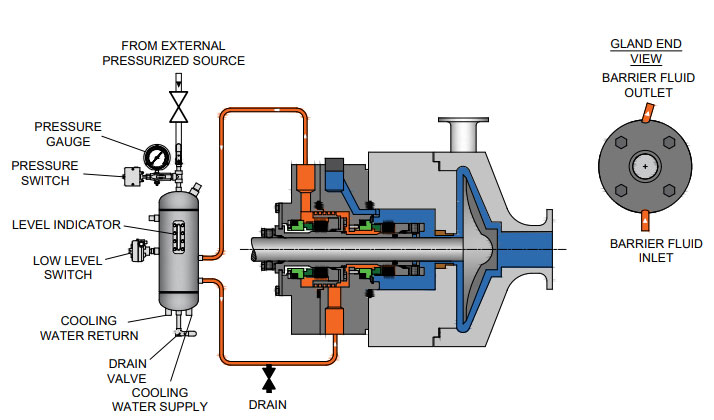
Uses a pressurized bladder accumulator to isolate pressurized gas from barrier fluid and delivers clean barrier fluid between the inboard and outboard seals at a pressure higher than the process fluid pressure; An internal pumping ring circulates the nitrogen barrier fluid; Bladder prohibits gas absorption into the barrier fluid and facilitates higher operating pressures than Plan 53A
Preferred for applications where the seal chamber pressure varies during pump operation; Uses a sensing line from the seal chamber into the piston accumulator to deliver barrier fluid from a reservoir at a constant, but higher pressure than the process fluid pressure; An internal pumping ring circulates the barrier fluid
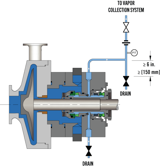
Delivers buffer gas (typically plant nitrogen) from an external source to the seal chamber at a lower pressure than the process pressure; Uses a coalescing filter to remove any moisture and particulate present in the plant nitrogen supply; Any process fluid vaporizing across the inboard seal is then swept into a closed collection system
Delivers barrier gas (typically plant nitrogen) from an external source to the seal chamber at a higher pressure than the process pressure; Uses a coalescing filter to remove any moisture and particulate present in the plant nitrogen supply; Allows a small amount of nitrogen to leak into the process fluid
If you’re making an investment in a new or upgraded seal support system, it’s well worth the time to work with an experienced Field Engineer who understands the importance of configuring the options for the specific pumping process.
Description: In comparison to the range of options in the above API seal flush plan categories, atmospheric side plans are much simpler. Their purpose is to provide a non-pressurized cooling flush to a mechanical seal"s faces on the atmosphere side to prevent or remove solid formations—crystallization, icing, and coking. Water, steam, and nitrogen are the typical flush fluids.
A quench improves atmospheric seal performance by absorbing or removing any process fluid leakage, preventing process fluid from being exposed to the atmosphere, and cooling or heating (relative to the process fluid temperature) to prevent the formation of solids proximate to the mechanical seal.
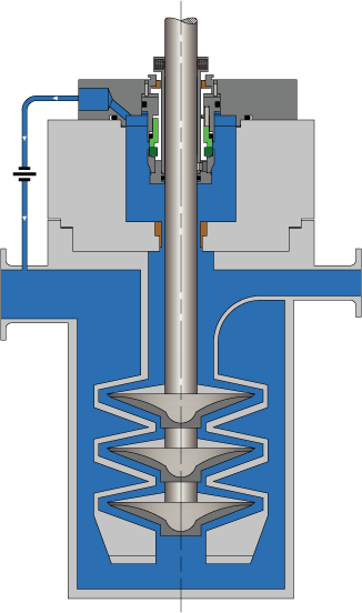
Delivers clean flush fluid from an external reservoir to the atmospheric side of a single seal preventing icing at ambient temperatures on the atmospheric side; Used for vertical pump applications
Delivers a low rate (2 to 4 PSI) of quench fluid (nitrogen, water, steam) from an external source to the atmosphere side of the seal. Typically uses a throttle bushing for containment.
The proper design of your flush plan is the biggest factor in ensuring long-term performance and reliability. You may have the in-house expertise to determine the appropriate API flush plans for the various pumps in a new installation or upgrades of existing pumps, but your outcomes will improve if you engage the service of an experienced, local partner. In working with process engineers for over the years, I can tell you first-hand that you’ll:
An experienced API seal flush plan partner has Field Engineers to evaluate each process and pumping conditions, fluid compatibility issues, and infrastructure considerations (on-site or virtually) to help determine plan requirements.
Swagelok has decades of expertise in helping refineries determine the proper API seal flush plans. We can design, fabricate, and thoroughly test the API seal plans prior to delivery. For over 50 years, Swagelok has been meeting the seal support needs of refineries in Northern California. We offer a complete range of API seal flush plans, available as kits or assemblies.
To learn howSwagelok Northen Californiacan assist you in choosing API seal flush plans that are right for your process needs by providing expert consultation, design, and fabrication,contact our teamtoday by calling
Pumping processes involving toxic or hazardous fluids that can’t risk leakage because of stringent environmental regulations require a double mechanical seal. Compared to a single mechanical seal, a double seal gives you significantly greater protection against leaks. With a double mechanical seal, you have an arrangement of two mechanical seals (a primary or inboard seal and a secondary or outboard seal) in series—back-to-back, tandem, or face-to-face. Each seal has a rotating (R) surface and a stationary (S) seal surface. These seals can be arranged in one of three patterns.
In a back-to-back arrangement, the stationary seal faces are positioned back-to-back with the rotating seal faces on the outside. The back-to-back arrangement is easy to install and used for many general pumping applications.
The tandem arrangement has the two pairs of seals mounted with the same orientation. This arrangement is preferred for toxic or hazardous applications because the outboard seal provides full pressure back-up, allowing the outboard seal to back up in the event of an inboard seal failure.
In the face-to-face arrangement, the rotating seal faces share a common stationary seal face. This arrangement is useful when equipment space is too constrained to permit back-to-back or tandem seal arrangements.
The American Petroleum Institute (API) Standard 682 classifies double mechanical seals into two configurations—pressurized and unpressurized. The pressurized arrangement has a barrier fluid delivered to the double mechanical seal by a seal support system. The barrier fluid is delivered at a higher pressure than the process fluid and must be chemically compatible with the process fluid as it will lubricate the inboard seal faces and mix with the process fluid. The unpressurized arrangement has a buffer fluid delivered to the double mechanical seal by a seal support system. The buffer fluid is delivered at a lower pressure than the process fluid.
The barrier and buffer fluids you use can be liquid or gas. They provide lubrication and help maintain the required operating temperature of the seal faces. The typical choices are water and water/glycol mixtures, low-viscosity petroleum or synthetic oils, kerosene, diesel, and nitrogen.
To gain a better understanding of the differences between the uses of barrier and buffer fluids, let’s look at two common API plans for double mechanical seals—API Plan 52 Buffer Fluid Seal Pot and API Plan 53A Barrier Fluid Seal Pot Pressurized by Nitrogen.
API Plan 52 takes buffer (unpressurized) fluid from a reservoir (seal pot), delivers it to the seal chamber, circulates it between the inboard and outboard seals using a pumping ring located driven by shaft rotation, then returns the fluid to the reservoir. In the event of an inboard seal failure, process fluid leaks into the seal chamber. When that occurs an increase in buffer fluid pressure and/or level alerts operators to the problem. The outboard seal, however, contains leakage until maintenance can replace the damaged seal.
This plan can include cooling coils in the reservoir to maintain the required buffer fluid temperature, visual or mechanical fluid level indicators, pressure and level transmitters, and connection to a collection system and buffer fluid replenishment source.
The overall design of this API plan for a double mechanical seal is relatively simple in comparison to other plans. Design decisions involving tubing size, length, geometry, type (carbon vs stainless steel), buffer fluid type, and volume of the buffer fluid reservoir are critical in maintaining the proper operating environment for the double seal. If you don’t have this expertise in-house, work with an experienced, local seal support system vendor to ensure the API Plan 52 is designed to meet your specific pumping requirements.
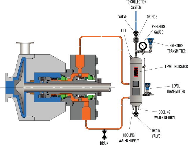
API Plan 53A is conceptually similar to API Plan 52 with the difference that the fluid being circulated between the double mechanical seals is under pressure. A pumping ring is used to circulate the fluid. The reservoir that contains the barrier fluid is pressurized by plant nitrogen. Reservoir pressure should be set a minimum of 20 to 25 psi (1.4 to 1.73 bar) above the maximum seal chamber pressure, allowing the barrier fluid to leak (and lubricate) across the inboard seal faces into the process fluid. For this reason, the barrier fluid must be chemically compatible with the process fluid.
Because barrier fluid is depleted as it moves across the inboard seal faces, it needs to be replenished. This can be done manually or automatically by way of a system that serves multiple pumps. API Plan 53A design options include reservoir type and volume, cooling coils, fluid level and pressure indicators, and transmitters to alert to level or pressure changes that indicate seal failure.
When you choose an API plan for a double mechanical seal, your primary decision is between a buffer or barrier plan. I’ve highlighted two of the API plans for double mechanical seals above to show the basic differences. There are multiple API plans for double mechanical seals to choose from—pressurization from bladder or piston accumulators, plant nitrogen delivered directly to the seal chamber, and custom-engineered external systems. Your choice will be determined by the process fluid and pumping conditions and the type of double mechanical seal your vendor recommends.
With this information in hand, it’s best to work with an experienced local seal support system vendor. They’ll be able to meet with you on-site to review the specifications for the pumping process, the pump, and the double mechanical seal. They’ll evaluate your existing infrastructure and its influence on seal support system design. Based on this information, they’ll then design the seal support system to meet the specific pumping requirements.
If you work with a global vendor like Swagelok, based on the design, we can quickly assemble and thoroughly test the API plan at our local facilities prior to delivery. We’re also conveniently available for follow-up consultations, on-site, remotely, or by way of a quick phone call.
For well over 50 years, Swagelok has worked closely with Northern California process industries to confidently choose the right API plans for pumping needs. Our locally based Field Engineers and certified technicians provide field verification of your seal support requirements, designs based on best practices gained from global experience.
To find out more about howSwagelok Northern California can help you choose the right API plan for double mechanical seals, as well as process and atmospheric side seals,contact our team today by calling
Morgan holds a B.S. in Mechanical Engineering from the University of California at Santa Barbara. He is certified in Section IX, Grab Sample Panel Configuration, and Mechanical Efficiency Program Specification (API 682). He is also well-versed in B31.3 Process Piping Code. Before joining Swagelok Northern California, he was a Manufacturing Engineer at Sierra Instruments, primarily focused on capillary thermal meters for the semiconductor industry (ASML).
After nearly six years of intensive work, the American Petroleum Institute (API) 682 mechanical seal standard is soon to be adopted. Since its introduction in 1994, API 682 has become “the” standard that sets the global tone for the procurement and operation of seal and supply systems for centrifugal pumps in the oil and gas sector as well as in the petrochemical industry. API 682 is a “living” standard that directly incorporates diverse practical experience in its regular updates.
Founded in 1919 and located in Washington, D.C., the API includes close to 500 companies from the oil and gas sector and the petrochemical industry. Since 1924, it has focused on technical standards. To this day, API has adopted roughly 500 standards that address diverse processes and components in detail—which ultimately ensure a maximum of operating and process reliability. API standards, which are clearly defined and in part attached to approval tests, do not take effect only in the U.S. In many cases, they have developed into worldwide industrial standards. API is often considered a synonym for safety and reliability.
Individual standards—including API 682 regulations for mechanical seals and seal supply systems—have become so popular that they have even been referenced in outside industry applications. The authors of the new edition point out that this was never the intention and clarify the actual purpose of the API 682 standards. The standards are for seal systems in pumps—not in agitators or compressors—and for oil and gas and petro chemistry—not for water supply or the food sector.
Initial information about mechanical seals was originally provided in the API 610 pump standard. During the 1990s, API 682 developed into a separate, more comprehensive standard for mechanical seals and supply systems. The API 682 standard is continually maintained and updated by end users and manufacturers. Another quality of API 682 is that it does not typically permit only a single technical solution. In addition to proven and tested standard solutions (defaults), the regulations also deliberately list alternatives (options) and even allow customized solutions (engineered solutions). This diversity is demonstrated more clearly in this edition than in previous ones.
The composition of the 25-member task force is representative of the practical way in which API approaches the topic of seals. Since 2006, the task force has been updating the 3rd Edition of API 682 that took effect in 2004 and is still valid. In addition to leading seal system manufacturers, the American-European expert panel—which intentionally counted on non-API member collaboration—also included renowned planning companies and representatives from some of the largest mineral oil groups, who are users of seal solutions.
While the currently valid API 682 edition included approximately 200 pages, the 4th Edition is 260 pages. The revised edition is organized into a body of text with 11 chapters and detailed annexes with a significantly expanded scope. For example, Annex I provides detailed information on more than 20 pages for API-conform seal qualification tests.
Default seals and options must be tested using five different media and clearly defined operating conditions representative of typical API applications. Together with the described seal designs, this yields a high number of possible test variations. In the process, the expended time per test and seal type can take up to 200 hours. The result for typical industry seal designs is documented in a test certificate and a detailed report. Customer-specific qualification tests can be agreed upon for engineered seals.
Essentially, checked and tested product safety is the core of the standard. The objective of API 682 is continuous operation of at least three years (25,000 operating hours subject to the legally stipulated emission values, or for maximum “screening value” of 1,000 parts per million by volume, EPA Method 21), increased operational reliability and simplified maintenance. The standards defined by API apply exclusively to cartridge systems with a shaft diameter of 20 to 110 millimeters and a defined range of operating conditions.
The 4th Edition also includes the revised product coding system (Annex D). The proven classification parameters “Category,” “Arrangement” and “Type” will be continued. They are listed first in the revised code and provide information about the setup and field of use of the respective API seal. The seal arrangement includes:Arrangement 1—single seals are differentiated
Details regarding the supply system—specified as “Plan”—are in the old and new code. The addition of precise information regarding material selection and shaft diameter is new. This gives more meaning to the code and guarantees a clear specification of the mechanical seal and its operation—from selection to documentation. Industry experts agreed that the expanded coding system will prove itself in practice and endure permanently.
The selection process of an API seal system is complicated. Several flow charts and tables on more than 10 pages are dedicated to this topic in the new edition. To provide more precision in the technical selection process when determining the arrangement, an alternative selection tool (Annex A.4) has been included in the 4th Edition for the first time. This method is based on the established “Risk & Hazard Code” and has been tested in practice.
The starting point is the pumped medium. Its real hazard potential is accurately recorded and described by the “Hazard & Risk Code” in the “Material Safety Data Sheets.” Decisions can be made quickly and securely, for example, about whether a single seal (Arrangement 1) will suffice, or if a double seal with barrier pressure system is required.
The experience-based, “lived” standard of the API 682 edition is demonstrated by the two silicon carbide (SiC) variants, reaction-bonded silicon carbide and self-sintered silicon carbide, which are treated equally as default materials for sliding surfaces in chemical (Category 1) as well as in refinery/oil and gas applications (Category 2 or 3). Until now, sintered SiC was set for chemical applications because of its superior chemical stability, whereas the reaction-bonded variant established itself in the refinery sector. This restrictive allocation was canceled because of practical application examples (best practices) that were brought to the attention of the task force, which called for a course correction.
Plan 53 with a pressurized barrier fluid belongs to the more complicated supply systems. In detail, three types are possible:Plan 53A is the solution with the constructively least amount of effort. The pressure on the barrier medium is generated directly via gas pressurization—normally with nitrogen—in the tank. However, the application has limits, since higher barrier pressures could cause a dissolution of the nitrogen in the barrier medium. The consequence would be the risk of inadequate lubrication in the sealing gap of the mechanical seal. That is why Plans 53B and 53C are used for higher barrier pressure.
A new prescribed refilling interval of at least 28 days has also been included in the 4th Edition of API 682. The fluid reservoir must be large enough to supply the seal with barrier fluid for this entire period—without refilling. To obtain the most compact reservoirs, the seal manufacturers are required to find optimized system solutions with minimal leakage values for the barrier medium.
The transition to transmitters as default is illustrative: the API specifications primarily concern operating and process reliability and only then consider economic viability. This universal application is also verified by the decision of the task force to permit only seamless pipes in the future for “Piping” for the supply systems. The use of welded pipes, which would be less expensive, was considered unacceptable.
The task force also addressed the topic of heat resistance of the instrumentation used in supply systems pragmatically. In the past, frequent debates occurred regarding whether supply systems for high-temperature applications—for example, a 400 C approved pump—have to be equipped with special instrumentation for high temperatures. Now the temperature specification for the instrumentation has been limited to 100 C. If instruments with higher temperature limits are required in the future, the customer has to inform the seal vendor accordingly.
The essential improvements, in addition to the technical supplements and updates, are the clear structures of the latest API regulation. The body of the text was tightened and structured appropriately, whereas technical details and background information were placed in the annexes. Some of the wording in individual chapters was revised to improve understanding.
The improved user friendliness is shown in Annex E, which addresses structured communication and data exchange between suppliers and customers. Descriptions that previously encompassed many pages in API 682 are now bundled into two compact checklists in the 4th Edition. The first list systematically describes what must be considered for inquiries and quotations. It specifies the data that needs to be provided and the additional information and documents with which it must be combined. For example, seal systems that deviate from standardized API solutions must be shown separately. Annex E is completed by a second checklist that shows in which order the documentation is necessary.
Apart from the numerous technical updates and improved user friendliness, one detail is visually the most striking innovation of this edition: all mechanical seals are equipped with red plugs in the supply connections of the seal gland upon delivery. Until the unit is installed, these plastic closures prevent the ingress of dirt in the seal. During operation, the connections are either assigned to pipelines, or the plastic plugs are replaced with enclosed metal plugs. An additional benefit is that the 4th Edition API seals are quickly identified by the red plugs. Editor’s Note: This article was previously published in Upstream Pumping Solutions, July/August 2013.
In one of the three previous parts this series of articles has dealt with the cost to reheat and/or evaporate flush injection from API Plan 32. It has also addressed industry technology that can be deployed to make seal flush piping plans more energy efficient while at the same time improving the reliability of the sealing device in the rotating equipment. Improvements and savings accrue from the application of best practice alternatives to API Piping Plans 32 and 54. The use of a modified API Plan 53A in the form of a Water Management System was described in Part 3; it eliminates the need to reheat and evaporate diluents. Available benchmark data prove the reliability benefits of this approach.
In the last of this series of articles, Part 4 now addresses the pumps used in condensate services. During many surveys the auditor will note pumps that are leaking hot condensate—a condition very often found in the paper industry. We can make good use of an authoritative source, the U.S. Department of Energy’s Steam Tip #8 by quoting from it in this Mechanical Seal Energy Audit:
Using separator pumps as a case in point, these pumps are taking condensate off the condensate receiver tank after the paper machine rolls. It is not customary for the receiver level controls to be manually overridden. Overrides can occur when the machine is brought on-line and steam must be kept in the rolls to prevent these from flooding. As steam enters the separator pump, the mechanical seal face set cannot seal steam. The lapped faces will become distorted and severe leakage will result.
Condensate pumps traditionally use API Plan 02, API Plan 11, API Plan 21, or API Plan 23. These plans use a single mechanical seal with one of these plan options.
The graphic on the next page shows hypothetically where each plan operates on a vapor-temperature curve for condensate. In order to understand how the traditional plans have been used, assume the condensate pump has a suction pressure of about 30 psig and the condensate is 200 degrees Fahrenheit (93 degrees Celsius). The discharge is 80 psig and there is naturally no change to the discharge temperature. For discussion purposes, the seal generates heat; assume the resulting temperature increase is 25 degrees Fahrenheit (-4 degrees Celsius). What is the pressure in the seal chamber? The seal chamber pressure depends on the pump design. Vanes on the back of the impeller or balancing holes near the eye of the impeller are used in design to control the axial thrust on the pump shaft. These pressure balancing techniques mean the pressure in the seal chamber will be closer to suction pressure. Again, it depends on the pump and seal manufacturers usually recommend consultation with the pump manufacturer to verify this pressure.
Seal chamber pressure and temperature: Pressure is just above the vapor point and the pump is pumping a liquid (water/condensate). The temperature and pressure in the seal chamber are such that the seal chamber contents are still in the liquid state.
API Plan 02. Depending on the actual pressure in the seal chamber, the seal faces generate heat and a pressure drop occurs across the seal face from 40 psig to 0 psig. Therefore, the fluid film between the seal faces could be vaporizing (“flashing”) as temperature increases and pressure drops.
API Plan 11 has been selected for this service. This plan increases the seal chamber pressure to 80 psig, assumes no cooling for seal face generated heat. The safety margin comes from higher pressure.
API Plan 21. A heat exchanger has been added to the discharge bypass line and the pressure is raised while the product is cooled. The safety margin comes from higher pressure and cooling of the condensate.
API Plan 23. The seal chamber is isolated and product is circulated through a heat exchanger. The mechanical seal circulates the liquid with a pumping ring (a “flow inducer”). This plan is more energy efficient than Plan 21 because the cooler only removes the heat generated primarily by the seal. There is also a small amount of heat soak from the process that passes an internal isolation restriction bushing in the seal chamber.
Failure: At any point during the life of the rotating equipment, if the pump sees steam because of operational upsets or the condensate receiver level causes the pump to run dry, the mechanical seal fails and the condensate pump leaks. This is the core issue to address.
The solution recommended is to use a dual seal with a secondary fluid consisting of treated clean condensate. The purpose of the secondary fluid is to cool the seal faces during normal operation and to serve as a lubricating fluid when the pump runs dry or steam is forced through the pump. This deals with the core failure issue of dry running or steam being forced through the pump.
By using a dual seal arrangement to mitigate the dry-running conditions caused by operational upsets affecting the condensate receiver, the user should expect years of leak-free service and energy efficiency benefits outlined in the Department of Energy Steam Tip #8.
Tom Grove is an executive vice president at AESSEAL Inc., one of the world’s leading specialists in the design and manufacture of mechanical seals and support systems. He can be reached at tom.grove@aesseal.com. Heinz P. Bloch, P.E., is one of the world’s most recognized experts in machine reliability and is a Life Fellow of the ASME, in addition to having maintained his registration as a Professional Engineer in both New Jersey and Texas for several straight decades. As a consultant, Mr. Bloch is world-renowned and value-adding. He can be contacted at heinzpbloch@gmail.com.
API 682 Seal. Viking’s seal chamber will accept almost any customer-specified brands and types of API 682-compliant Category 1, 2 or 3 cartridge mechanical seals, and can provide API seal plans to meet application requirements. Standard seal is a category 2 single mechanical seal. Carbon vs. silicon carbide with API Plan 13.
3mm corrosion allowance above Maximum Allowable Working Pressure (MAWP). The XPD 676 has an additional 3mm corrosion allowance built into all pressure containing components over and above our standard steel Universal Seal series pumps.
Casing drain and seal chamber vent. XPD 676 has cast-in casing drain with ANSI Class 300 RF flange and seal chamber vent to completely drain the casing before maintenance.

The Chesterton A2382 Cartridge Dual Seal is designed specifically for stringent refinery applications, meeting the API 682 Standard, Type A pusher seal requirements. Our superior API seal combines proven Chesterton technology and extensive R&D qualification testing. The A2382 Seal design delivers high reliability and meets tough emissions requirements through advanced seal face design and low heat generation.
Chesterton"s API seals provide a versatile approach to refinery, chemical, and petrochemical sealing. The A2382 is a double-balanced seal designed to handle pressure reversals. The innovative design simplifies seal selection and improves standardization throughout the plant. API 682 and ISO 21049 compliant.


 8613371530291