
api mechanical seal for sale
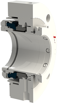
The Flexaseal Style 59A is designed specifically to conform to API 682 Category 2 Applications for Midstream and Downstream Oil and Gas Applications. Standard design features include:
The 59A is also available with contacting and noncontacting secondary sealing. The Flexaseal FC seal (Available as 59A/FC) provides decades of proven operational reliability as a contacting secondary seal. The Flexaseal FGSA (Available as 59A/FGSA) is our newest lift-off design for API applications that require a noncontacting secondary seal.

The API plans presented in this section are developed in accordance with the API 682, 3 revision / API 610, 10 revision standard. This is the standard scheme of the drilling pipes, which are widely used in industry. It is possible to customize these plans to meet the needs of customers.
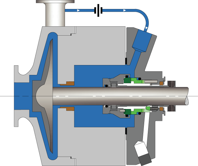
The flushing of the seal from the outlet to the seal chamber via the aperture and flushing the seals from the seal chamber to the inlet through the diaphragm
Diagram of the system for ensuring the operation of a single seal with an impeller that creates fluid circulation through the stuffing box along an Autonomous circuit.
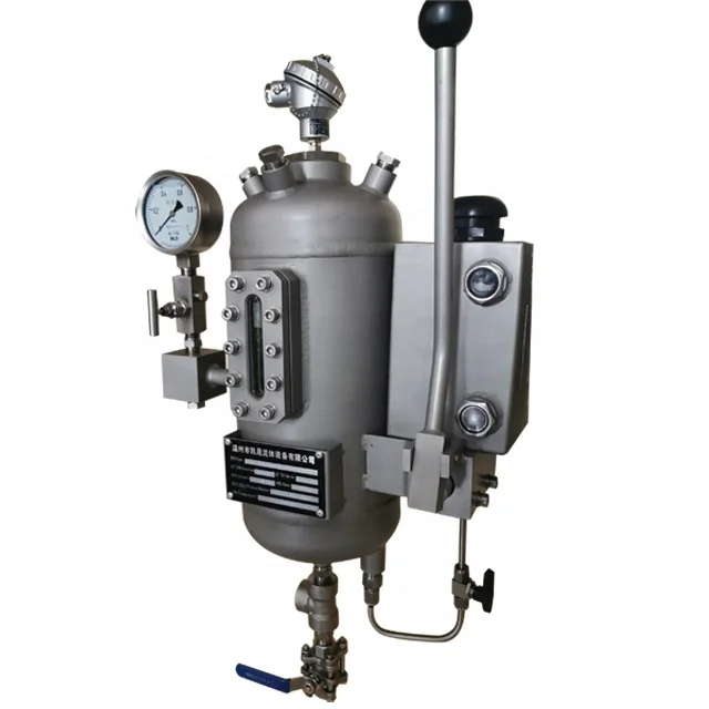
If the pressure in the oil seal chamber of the pump is less than the design pressure of the tank (4mpa), the installation of a safety valve on the tank pipelines is not required.
"Tandem" type mechanical seals can be used both with a refrigerator at the pump"s working medium temperature up to 400 °C, and without it at the working medium temperature up to 150 °C.
Diagram of the system for ensuring the operability of a double seal with a tank. The system operates at constant maintenance of the pressure of the shut-off fluid (pressure in the tank) within:
At pump working medium temperatures up to 150°C seals are used without a refrigerator, at the temperature of the pumped medium 150...400°C-with a refrigerator.
For servicing seals of a group of pumps that perform the same task and are located close to each other, it is possible to use the system diagram shown below.
The most commonly used scheme is a system with the supply of shut-off fluid from a separate pipeline with an overpressure m through the seal of the threads.
At pump working medium temperatures up to 150°C seals are used without a refrigerator, at the temperature of the pumped medium 150...400°C-with a refrigerator.
For condensate pumps, where dry operation of the mechanical seals is not excluded, the guaranteed supply of the shut-off fluid can be carried out according to the following scheme.
At pump working medium temperatures up to 150°C seals are used without a refrigerator, at the temperature of the pumped medium 150...400°C-with a refrigerator.
API plan 65 allows you to determine the volume of leaks through the mechanical seal. If the friction pair breaks through, the external strapping tank is equipped with an upper-level alarm that will trigger as soon as the liquid level in the tank increases.
API Plan 62 delivers an external quench fluid to the atmospheric side of the seal. A typical application in a refinery is the prevention of coking on seal faces in hot hydrocarbon service by employing a steam quench. Nitrogen or clean water may also be used to quench or cool and clean the atmospheric side of the seal.
See page 77 of the Mechanical Seal Support Systems Application Guide for additional details and ordering information. Contact your authorized Swagelok sales and service center for information on optional components.
API Seal Plan 52 utilizes a reservoir and circulates an unpressurized buffer fluid between the inboard and outboard seals. To provide positive circulation through the support system and into the seal, a pumping ring is employed. Frictional losses in the buffer fluid inlet and outlet lines should be minimized by selecting the proper tube size, using large radius and/or 45 degree bends, and reducing the length of tubing runs. Seal Plan 52 is commonly used with light hydrocarbons or fluids with a high vapor pressure. The buffer fluid must be compatible with process fluid as inboard seal leakage will eventually mix with the buffer fluid.
Plan 52 is available as a seal pot assembly. The associated field installation kit for use in connecting the seal pot assembly to your system is also available. Assembly components may include:
See page 31 of the Mechanical Seal Support Systems Application Guide for additional details and ordering information. Contact your authorized Swagelok sales and service center for information on optional components.
Please contact AESSEAL Systems Division for further details. Tel: +44 (0)28 9266 9966 Email: systems@aesseal.com For more information, and a video demonstrating the piping plan in operation, select a plan below
![]()
Pump Projects is your go-to resource for advice, sales and service for mechanical seals for pumps. We have the internal resources to help you with this complex issue.
A mechanical seal is simply a method of containing fluid within a vessel (typically pumps, mixers, etc.) where a rotating shaft passes through a stationary housing or occasionally, where the housing rotates around the shaft.
A seal code is an abbreviated method of communicating basic specifications for the mechanical seal. Sadly, the seal code has been changed with every edition of API 682. Fortunately, the new code, described in API 682 4th Edition Annex D, is the best to date and includes some concepts and codes from the historical API 610 seal code. The new code uses eight fields:
API 682 4th Edition was the first edition to include materials in the description and in many ways represents a combination of API 682 coding and the old API 610 codes.
4th Edition coding comprises four sections, some being sub-divided. The table below shows the construction of a typical seal code, it is intended to accurately describe the seal and seal system being implemented in a given application.
T: Seal type A, B or C per API 682 4th Edition definitions. For dual seals using different inner and outer seal types, show both types using the format inner/outer.
Note that the codes used for Design Options are the same as those used in API 610 for materials that are included in both systems. On the other hand, some materials cannot be specified because API 682 does not recommend them. Such materials must be specified with an “X”.
For many years the pump standard API 610 contained a mechanical seal coding system which became widely used in industry. This coding method provided a reference to the nomenclature and features used with mechanical seals that were current during that time period. While this coding method is obsolete it still is still being used in some areas of industry. It is presented herein as a historical reference only.
A very commonly used code was BSTFM which translates to a balanced single seal with throttle bushing in the gland plate. Gaskets would be FKM (fluoroelastomer). Seal faces would be carbon vs nickel bound tungsten carbide.
After more than five years of planning, the American Petroleum Institute (API) is preparing to release the 4th edition of API Standard 682 (ISO 21049:2011). The API 682 standard, which dates back to 1994 and is formally known as Shaft Sealing Systems for Centrifugal and Rotary Pumps, offers specifications and best practices for mechanical seals and systems to pump end users.
The standard’s latest edition began to take shape in 2006, when API formed a 4th edition task force to respond to end users’ questions and comments about previous editions. The task force soon realized that major changes, including reorganization and editing, would be necessary. While addressing every aspect of the resulting 4th edition (which is more than 250 pages long) would be impossible, this article summarizes the standard’s main points.
Those who use API 682 should understand the standard’s scope and remember that the standard does not include specifications for equipment outside that scope, such as engineered seals or mixers. Another important but often misunderstood point is that API 682’s figures are illustrative and not normative in their entirety.
For example, one of API 682’s figures shows a fixed throttle bushing combined with a rotating Type A seal, but seal manufacturers do not always have to combine these two components. The standard provides normative details in clauses and tables to help purchasers distinguish between requirements and suggestions.
The 4th edition continues to divide seals into three categories, three types and three arrangements. For all practical purposes, seal manufacturers can combine a seal’s component parts into nearly any orientation or configuration. Each orientation and configuration has advantages and disadvantages with respect to certain applications, performance and system disturbances.
Before the 4th edition, API 682 did not specify a minimum clearance between the inside diameter of a stationary seal part and the outside diameter of a rotating seal part. The 4th edition specifies this minimum clearance—typically the clearance between the sleeve and the mating ring. The specified clearances are representative of standard clearances that end users have used for decades. End users should not consider seal components to be “shaft catchers” to restrict shaft movement. The minimum clearance specified in API 682 also applies only to equipment within the standard’s scope. Equipment outside that scope, such as non-cartridge seals, older pumps, non-API 610 pumps and certain severe services, might benefit from larger clearances.
The new standard also updates the default bushings for the gland plate for the three seal categories. Fixed throttle bushings are now the default for Category 1 only, while floating bushings are the default for Categories 2 and 3.
While the 4th edition features the recommended seal selection procedure from the standard’s first three editions, it adds an alternative selection method in Annex A. Proposed by task force member Michael Goodrich, this alternative method recommends using material data sheet information to select a sealing arrangement.
Plans 66A and 66B are new to the standard, although end users have used them previously in pipeline applications. These plans detect and restrict excessive leakage rates in case of an Arrangement 1 seal failure.
The 4th edition has revised the data sheets in Annex C extensively to make them the same for all seal categories. Only two data sheets are included in the 4th edition—one in metric units and one in U.S. customary units. The new edition also folds Annex J into Annex E.
Previous editions of API 682 required metal plugs and anaerobic sealants when shipping new or repaired cartridges. After much debate, the task force decided that threaded connection points should be protected with plastic plugs for shipment. These plastic plugs should be red and have center tabs that operators can pull easily to distinguish the plugs from metal plugs. Shippers should also attach yellow warning tags to the plugs to indicate that end users need to remove the plugs before operation.
Although tutorial notes are scattered throughout API 682, this edition expands the tutorial section, Annex F, from seven pages to 42 pages. The expanded annex includes illustrative calculations. In particular, users interested in systems such as Plan 53B will find Annex F to be useful.
The 4th edition of API 682 is the product of more than 20 years of discussion, debate, usage and peer review. It includes a strong set of defaults and is by far the best and most logical starting point for mechanical seal and systems use. Equipment operators should take the time to familiarize themselves with API 682 to get the most out of this comprehensive standard.
![]()
Pressurized barrier fluid reservoir and circulation tank to ensure media will not leak into atmosphereDesigned to ASME Section VIII, Division 1 standardsAvailable to build to (U) and (UM) stamps, registered with national boardFormation of fluid between seal faces provide a longer seal lifeModular design for various combinations of instruments and componentsAvailable with refill pumps, transmitters, switches and cooling coils
Tank Capacity: 2 Gallon, 3 Gallon, or 5 Gallon in 6" or 8" diameterOperating Pressure: 400 PSI @ 200°FTank Material: 316/316L SCH 40Cooling Coil: 1/2” x 0.065” wall seamless tube; 20’ long 316/316LLevel Gauge: Weld Pad– Size 7, 10 ¼” VisibilityHydrostatic Test Pressure: 525 PSIAllowable Temp: -20° F to 200° FFill Port: 3/4” NPTSeal Connections: 1/2” NPTLevel Switch Connections: 3/4” NPT
Carotek manufactures Seal Pot Pressure Vessel Tanks in our Charlotte facility in Matthews, NC. The seal pots are built toASME Section VIII, Division 1, E2007, 2008a, Addenda and are available with ASME “U” and “UM” code stamps. As a premier industrial seal pot manufacturer, we offer standard and custom built ANSI / API mechanical seal support systems for industrial, chemical, and petrochemical applications. Seal pots provide a protective buffer between the product and the atmosphere, and isolate potential product leaks to the atmosphere. As a safety measure, seal pots perform a vital duty protecting the environment and personnel from the dangers of hazardous materials
Our Seal Pots our fully Made in America and meet all the requirements of ANSI and API specifications. Our modular designs are adaptable and can be combined with cooling coils, level switch/transmitters, pressure switch/transmitters, air coolers, and circulating pumps for a wide variety of applications. They are durable, flexible, and offer reliable performance for your demanding operations. Modular design supports various combinations of instruments and components such as built in refill pumps, transmitters, switches and cooling coils.
Seal Pot ASME Certificate of AuthorizationMade in AmericaQuick QuotesQuick DeliveryExpert application assistanceMillwright qualityTIG and MIG weldedBare Tanks with coil can be shipped next dayAvailable with ASME code stamp

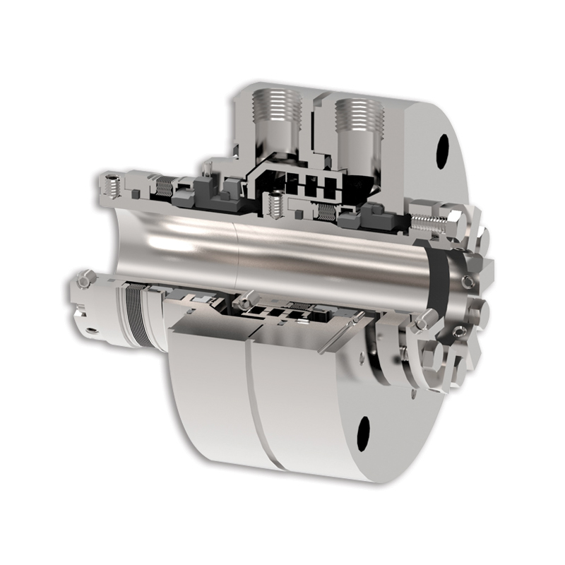
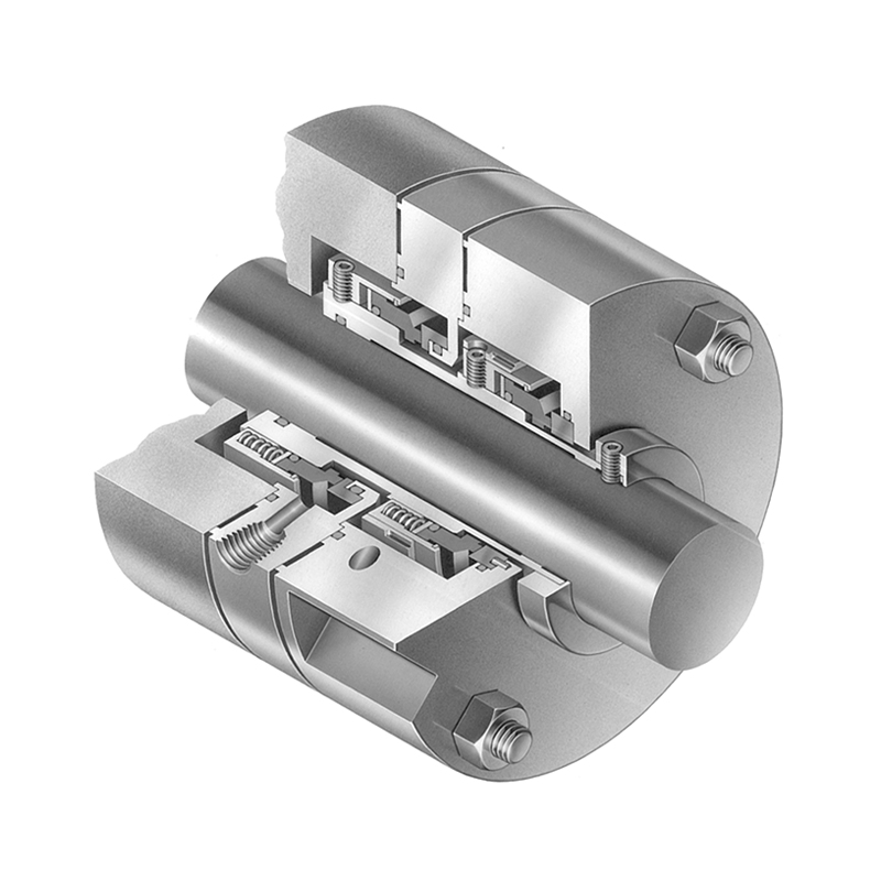
The MAFFS has developed API (American Petroleum Institute) 682 seals for the oil and gas industry market. The MAFFS Type A pusher seal is available in Arrangement 1, 2 and 3. An Arrange- merit 1 seal is a single contacting wet cartridge seal with a Throttle bush. Arrangement 2 cartridge seal is the same configuration as the Arrangement 3 seal but is an un-pressurized dual seal where the barrier fluid pressure is kept lower than the seal chamber fluid pressure. The outboard seal will provide back up of hazardous fluids in case of Inboard Seal failure. MAFFS has designed, manufactured and tested to meet API 682 requirement, Type A pusher seal in Arrangement 1 and Arrangement 3 (dual pressurized cartridge seal) for the market. In an Arrangement 3 design the barrier fluid pressure is kept higher than the seal chamber pressure and is designed to handle and contain hazardous and light hydrocarbon fluids. The Inboard seal is specially designed to handle reverse pressure. Outboard Seal is same as Arrangement Seal. With many years of experience in seal design, manufacturing and testing for the industrial market, MAFFS has the experience to solve your sealing problems. Expert Engi-neering provides optimum sealing solutions to meet customer needs.

In Fourth Edition, an alternative method was presented based on methodology proposed by Michael Goodrich. This alternative method is primarily directed towards selection of the sealing arrangement using Material Data Sheet information. The alternative method takes into account the toxicity of a process fluid and not just its physical properties. The selection is based on the fluid hazard code according to the United Nations Globally Harmonized System of Classification and Labeling of Chemicals (GHS) and the European Union Regulation on the classification, and packaging of substances and mixtures. The substances are categorized in “H” statements and “R” codes.
Tables are provided placing the H statement or R code into a one of four groups. A Seal Selection Logic is then provided based on these groups to select the seal arrangement including the additional need for a floating carbon bushing for Arrangement 1 seals.
A test seal cartridge is specified by the parameters in this column and the representative materials and geometry of its core seal components. In dual seals combinations of face material pairs, types and flexible element positions are possible. b For a specific service, a seal vendor"s commercial product only needs to be tested in the representative test fluid. c Default d 2CW-CS and 2NC-CS shall be tested as inner seal, arrangement and containment seal in accordance with I.4.1 and I.4.5. e 3NC-BB, 3NC-FB and 3NC-FF shall be tested as arrangement in accordance with I.4.1 and I.4.6. f Commercially available petroleum based diesel fuel. This seal selection takes into account exposure limits for hazardous or toxic chemicals and mixtures of these chemicals, and is thus a benefit to a broader audience, not just petroleum refining based processes. It is important to note that a hazard assessment is only one criterion which must be considered.
Other consideration such as the fluid properties, dry running of the equipment, seal leakage detection strategies, leakage disposal options and process contamination must also be considered before making a final selection.


 8613371530291