
api mechanical seal pricelist
Please contact AESSEAL Systems Division for further details. Tel: +44 (0)28 9266 9966 Email: systems@aesseal.com For more information, and a video demonstrating the piping plan in operation, select a plan below
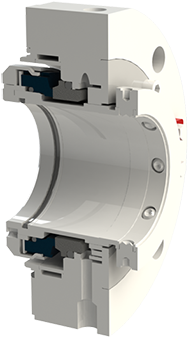
The MTM250 series of cartridge mechanical seals has been specially designed to be installed on rotary machines as fast as compressors and turbines. It can be realized in different materials, both for the sliding faces and structural materials and it is able to withstand speeds up to 32 m / s. It is available from diameter 40 up to 200mm and it is today mainly used on screw compressors in presence of lubrication. Its design has been optimized thanks to the testing done directly on the field with one of the major manufacturers in the industry, following out the API 619 norm. Today it is used for pumping gas, such as propane, methane, butane and major hydrocarbons. The structure of the MTM250 cartridge mechanical seal is a double type structure with an external safety sealing, SafetyMTM, which becomes the third seal in case of failure of the two main seals.
The APILITE (R) mechanical seal is a new addition to the API 682 RDT cartridge seal family. It is designed for sealing heavy and light hydrocarbons, including VOCs, and other hazardous fluids at oil refineries and petrochemical plants, gas plants, and chemical plants. APILITE RDT seal is an o-ring dual seal to be used with API Plan 52, 53, or 54.
Minimized bending of seal rings allows for stable operation under higher pressures and for longer MTBR (mean time between repair) because of less wear;
Interchangeability of many parts and design solutions with the SD APITERM seal reduces inventory of spare parts, lets the seal survive under pump dry-running, and decreases prices by encreasing parts production volume;
Mechanical seals are indispensable for sealing rotating shafts. They make sure that the fluid handled remains in the system, prevent emissions and thus protect the environment from contamination. High-quality shaft seals in the form of mechanical seals also ensure maximum economic efficiency and operating reliability for pumps. This is crucial because the majority of repairs arise due to sealing problems.
And this is where KSB’s mechanical seals can make a difference: as well as impressing with a robust design, they offer straightforward installation and optimal integration in the seal chamber – ensuring reliable and efficient system operation.
The scope of our mechanical seal product range far exceeds any other seal manufacturer. From small elastomer bellows seals used in millions of domestic water pumps to double mechanical seals that ensure maximum sealing safety and large, highly customized dry-running gas seals for mission critical high speed turbo compressors, John Crane has the right product for any application.
The right seal support system is critical for promoting seal reliability. John Crane customizes support systems to meet a variety of seal specifications, contributing to safe, cost-effective, reliable operation and reducing harmful environmental effects. Our support systems comply with constantly changing design codes and standards, and meet the increasingly stringent demands on end users.
Our comprehensive suite of seal face technologies are designed to overcome rigorous sealing challenges, including limited seal face lubrication and severe-service duties that adversely affect reliability, operational costs and seal life. Designed by our engineering experts, John Crane’s face treatment options help your equipment power through low-lubricity and dry-running conditions by using advanced micromachined patterns and features to improve seal face lubrication to optimize the performance of rotating equipment in all process industries
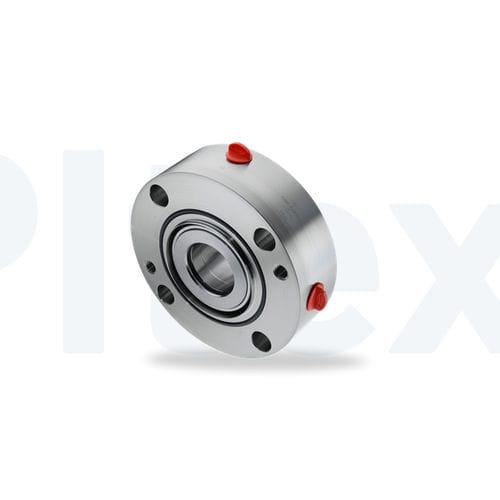
Isomag’s advanced magnetic face technology delivers unparalleled performance. The lapped flat faces create a positive liquid tight seal preventing lubricant leakage and the ingress of contaminants in both static and dynamic conditions on horizontal and vertical equipment alike. By optimizing the magnetic energy loading, Isomag’s are capable of running at shaft speeds well above average (up to 15,000 feet per minute) providing the ability to effectively seal the bearing housings on a wide variety of applications
Do you want to minimize leakage from your pumps in an effective manner? This is a challenge operators and maintenance managers face on a daily basis, which can prove costly. John Crane offers a wide selection of packing materials in compression packing, automatic packing, floating packing, and injectable packing. Learn more about our variety of packing equipped to handle the vast majority of sealing solutions and available for nearly all applications.
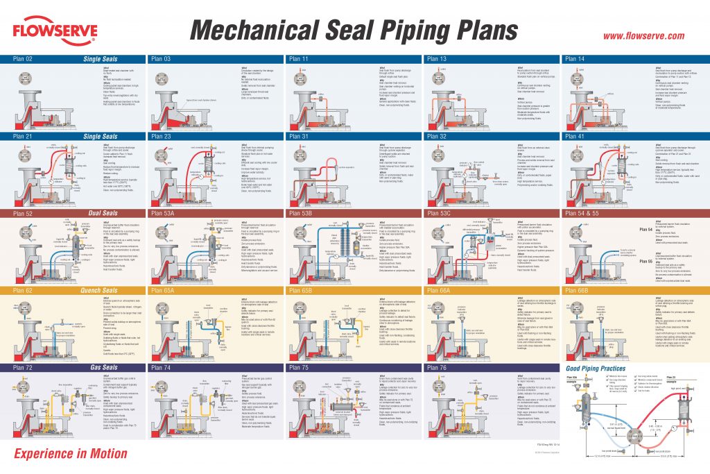
To keep mechanical seal systems functioning as long as possible, we recommend using standardized seal piping plans. Detailed API seal piping plans ensure minimal seal face wear by maintaining the optimal seal chamber environment.
Since they were first formulated, seal piping plans have been maintained and remodeled by the American Petroleum Institute (API). Current plans are based on API 682 and are sorted numerically. In some cases, designated letters are also used to differentiate between plans.

The Flexaseal Style 59A is designed specifically to conform to API 682 Category 2 Applications for Midstream and Downstream Oil and Gas Applications. Standard design features include:
The 59A is also available with contacting and noncontacting secondary sealing. The Flexaseal FC seal (Available as 59A/FC) provides decades of proven operational reliability as a contacting secondary seal. The Flexaseal FGSA (Available as 59A/FGSA) is our newest lift-off design for API applications that require a noncontacting secondary seal.
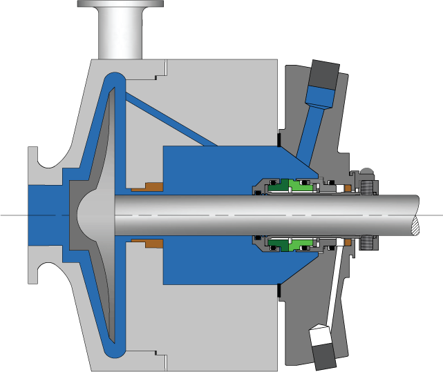
Pumping processes involving toxic or hazardous fluids that can’t risk leakage because of stringent environmental regulations require a double mechanical seal. Compared to a single mechanical seal, a double seal gives you significantly greater protection against leaks. With a double mechanical seal, you have an arrangement of two mechanical seals (a primary or inboard seal and a secondary or outboard seal) in series—back-to-back, tandem, or face-to-face. Each seal has a rotating (R) surface and a stationary (S) seal surface. These seals can be arranged in one of three patterns.
In a back-to-back arrangement, the stationary seal faces are positioned back-to-back with the rotating seal faces on the outside. The back-to-back arrangement is easy to install and used for many general pumping applications.
The tandem arrangement has the two pairs of seals mounted with the same orientation. This arrangement is preferred for toxic or hazardous applications because the outboard seal provides full pressure back-up, allowing the outboard seal to back up in the event of an inboard seal failure.
In the face-to-face arrangement, the rotating seal faces share a common stationary seal face. This arrangement is useful when equipment space is too constrained to permit back-to-back or tandem seal arrangements.
The American Petroleum Institute (API) Standard 682 classifies double mechanical seals into two configurations—pressurized and unpressurized. The pressurized arrangement has a barrier fluid delivered to the double mechanical seal by a seal support system. The barrier fluid is delivered at a higher pressure than the process fluid and must be chemically compatible with the process fluid as it will lubricate the inboard seal faces and mix with the process fluid. The unpressurized arrangement has a buffer fluid delivered to the double mechanical seal by a seal support system. The buffer fluid is delivered at a lower pressure than the process fluid.
The barrier and buffer fluids you use can be liquid or gas. They provide lubrication and help maintain the required operating temperature of the seal faces. The typical choices are water and water/glycol mixtures, low-viscosity petroleum or synthetic oils, kerosene, diesel, and nitrogen.
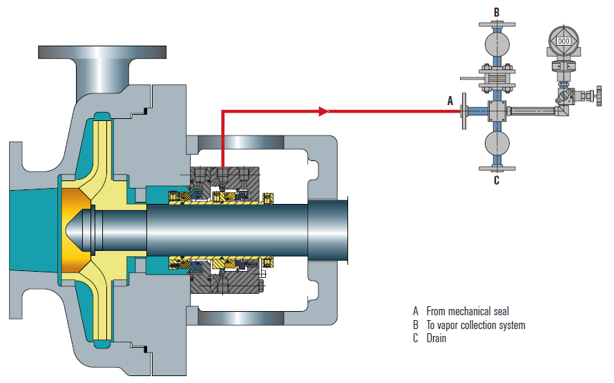
To gain a better understanding of the differences between the uses of barrier and buffer fluids, let’s look at two common API plans for double mechanical seals—API Plan 52 Buffer Fluid Seal Pot and API Plan 53A Barrier Fluid Seal Pot Pressurized by Nitrogen.
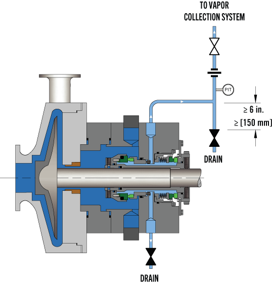
API Plan 52 takes buffer (unpressurized) fluid from a reservoir (seal pot), delivers it to the seal chamber, circulates it between the inboard and outboard seals using a pumping ring located driven by shaft rotation, then returns the fluid to the reservoir. In the event of an inboard seal failure, process fluid leaks into the seal chamber. When that occurs an increase in buffer fluid pressure and/or level alerts operators to the problem. The outboard seal, however, contains leakage until maintenance can replace the damaged seal.
This plan can include cooling coils in the reservoir to maintain the required buffer fluid temperature, visual or mechanical fluid level indicators, pressure and level transmitters, and connection to a collection system and buffer fluid replenishment source.
The overall design of this API plan for a double mechanical seal is relatively simple in comparison to other plans. Design decisions involving tubing size, length, geometry, type (carbon vs stainless steel), buffer fluid type, and volume of the buffer fluid reservoir are critical in maintaining the proper operating environment for the double seal. If you don’t have this expertise in-house, work with an experienced, local seal support system vendor to ensure the API Plan 52 is designed to meet your specific pumping requirements.
API Plan 53A is conceptually similar to API Plan 52 with the difference that the fluid being circulated between the double mechanical seals is under pressure. A pumping ring is used to circulate the fluid. The reservoir that contains the barrier fluid is pressurized by plant nitrogen. Reservoir pressure should be set a minimum of 20 to 25 psi (1.4 to 1.73 bar) above the maximum seal chamber pressure, allowing the barrier fluid to leak (and lubricate) across the inboard seal faces into the process fluid. For this reason, the barrier fluid must be chemically compatible with the process fluid.
Because barrier fluid is depleted as it moves across the inboard seal faces, it needs to be replenished. This can be done manually or automatically by way of a system that serves multiple pumps. API Plan 53A design options include reservoir type and volume, cooling coils, fluid level and pressure indicators, and transmitters to alert to level or pressure changes that indicate seal failure.
When you choose an API plan for a double mechanical seal, your primary decision is between a buffer or barrier plan. I’ve highlighted two of the API plans for double mechanical seals above to show the basic differences. There are multiple API plans for double mechanical seals to choose from—pressurization from bladder or piston accumulators, plant nitrogen delivered directly to the seal chamber, and custom-engineered external systems. Your choice will be determined by the process fluid and pumping conditions and the type of double mechanical seal your vendor recommends.
With this information in hand, it’s best to work with an experienced local seal support system vendor. They’ll be able to meet with you on-site to review the specifications for the pumping process, the pump, and the double mechanical seal. They’ll evaluate your existing infrastructure and its influence on seal support system design. Based on this information, they’ll then design the seal support system to meet the specific pumping requirements.
If you work with a global vendor like Swagelok, based on the design, we can quickly assemble and thoroughly test the API plan at our local facilities prior to delivery. We’re also conveniently available for follow-up consultations, on-site, remotely, or by way of a quick phone call.
For well over 50 years, Swagelok has worked closely with Northern California process industries to confidently choose the right API plans for pumping needs. Our locally based Field Engineers and certified technicians provide field verification of your seal support requirements, designs based on best practices gained from global experience.
To find out more about howSwagelok Northern California can help you choose the right API plan for double mechanical seals, as well as process and atmospheric side seals,contact our team today by calling
Morgan holds a B.S. in Mechanical Engineering from the University of California at Santa Barbara. He is certified in Section IX, Grab Sample Panel Configuration, and Mechanical Efficiency Program Specification (API 682). He is also well-versed in B31.3 Process Piping Code. Before joining Swagelok Northern California, he was a Manufacturing Engineer at Sierra Instruments, primarily focused on capillary thermal meters for the semiconductor industry (ASML).
discharge capacity up to 12960 m3/hr at 365 rpm and 10368 m3/hr at 285 rpm. The castings, shafting, sleeves, and fasteners comply with NACE MR0175/ ISO 15156 and ME010. It has Dual Pressurized Mechanical Seal with plan 54.


 8613371530291