
mechanical seal installation factory

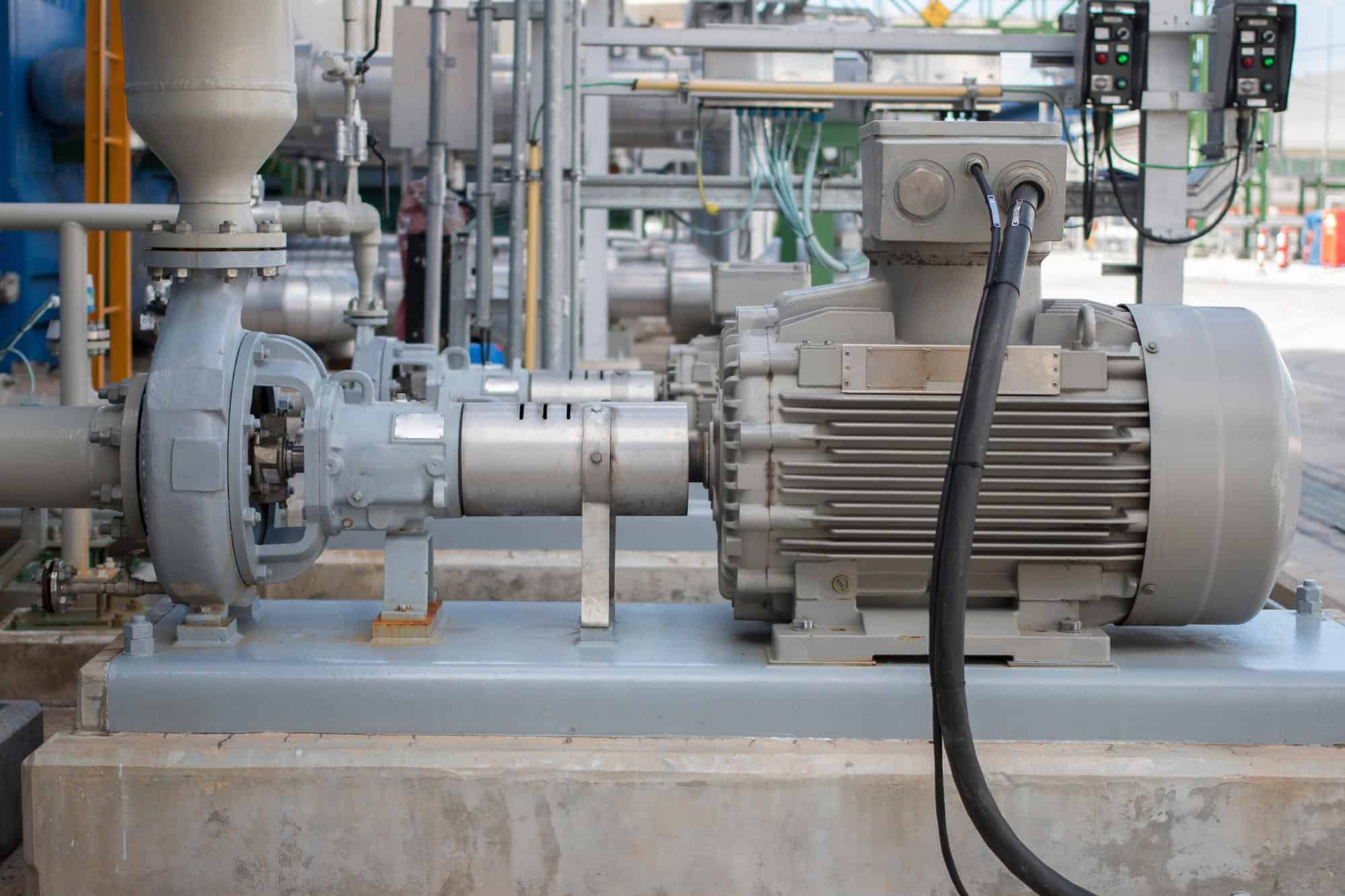
The rotating shaft of a centrifugal pump penetrates the back end of a pump casing through a stuffing box or seal chamber. The primary purpose of a mechanical seal in a centrifugal pump is to prevent fluid from leaking to the atmosphere along this rotating shaft. Selection of the right mechanical seal for each pump application is critical when considering safety and reliability. Mechanical seal failure is typically one of the primary reasons why pumps fail. In this guide, the experts at PumpWorks will show you the steps to install a mechanical seal in your centrifugal pump with minimal downtime.
A mechanical seal requires two extremely smooth and flat (lapped) seal faces in contact, one rotating with the shaft and the other stationary with the casing. These seal faces are sealed to their appropriate holders through the use of secondary seals (o-rings or gaskets). The faces are mechanically energized and flexible so that they can be placed into contact and move to make up for static and dynamic misalignments as well as wear. The seal faces require lubrication from the fluid and break down this fluid as it tries to escape through the seal faces, resulting in slight vapor release. All mechanical seals leak…vapor…when selected and sized correctly.
You may be wondering how long the mechanical seal installation procedure will take. By following the 10 simple steps listed below, you’ll have the job done in no time.
If your pump is a ‘back pull-out’ design, remove the spacer element in the pump coupling. Then remove the casing bolts and slide the remainder of the pump away from the casing. You are now able to access the mechanical seal without having to disconnect the casing from the inlet and outlet piping. If the pump is not a ‘back pull-out’ design, you will need to disconnect the complete pump after disconnecting the coupling between the pump and motor shaft. If the pump is a close coupled design (the pump uses the shaft of the motor as its shaft and the motor directly bolts onto the back of the pump), you will need to remove the entire pump/motor. Remove the casing bolts and remove the casing.
The mechanical seal is located behind the impeller on the pump shaft. Impellers are either screwed onto the shaft or held in place via a bolt. To remove the screwed-on impeller from the shaft, use a wrench to hold the shaft in place and rotate the impeller clockwise until it is completely unscrewed. To remove a bolted impeller, hold the shaft in place and remove the bolt.
You can now directly access both the rotary and stationary seal parts. The rotary parts are typically held in place along the shaft using set screws. Remove the set screw and slide off the rotary seal parts. Remove the stationary part of the seal from the casing or seal chamber bore.
Now it’s time to place a new mechanical seal onto the shaft. Carefully slide the replacement seal parts along the shaft. Using a new o-ring or gasket material, press the stationary part into the casing or seal chamber bore. Follow the instructions for setting the rotary portion back onto the shaft correctly. This is a crucial step.
CAUTION: Always install mechanical seals in a clean working space. Don’t touch the front of the seal faces as it is susceptible to body oils and may not function properly if compromised. Keep the seal in its packaging until it’s time to install.
For back pull-out designs, slide the back pull-out assembly up against the installed casing and bolt it in place. Checking pump alignment will be necessary after step 9 below. For close coupled or non-back pull-out designs, reinstall the casing using the casing bolts. In all cases, torque the casing bolts in accordance with the pump Installation, Operation, and Maintenance (IOM) manual.
Always review safety precautions found in the pump IOM. Always use the Pump IOM when working on any pump. Install the mechanical seals using the specific instructions from the mechanical seal manufacturer. Lastly, always make sure the pump and motor are realigned within 001” – 002”. Misalignment will cause premature mechanical seal failure.
PumpWorks is the go-to company for all your mechanical seal installation needs. Our pump manufacturing company offers over 30 years of experience in the troubleshooting, selection, application, and repair of mechanical seals. We serve a wide range of process industries such as petroleum refining, chemical, food and beverage, water and wastewater, power, and more.
Three variables that most affect the design selection of mechanical seals are: equipmentcharacteristics, application and operating conditions, and the leak rate objective.
The first decision, however, rests in determining if one or multiple seals are required. This often has the potential for a devastating impact on overall performance and reliability.
Relatively clean process fluids with adequate lubricating properties can be contained with a single-seal arrangement. These seals are typically less expensive to install and simpler for teams to operate and maintain. If a separate lubrication system is required, a double seal arrangement will be needed. This will help ensure mechanical seal reliability.
The amount of leakage to atmosphere, which is dictated by the plant’s leak rate objectives and/or regulatory requirements, must be controlled by the seal design chosen. All end-face mechanical seals operating effectively on high-speed applications allow a small amount of vapor to pass through the primary seal interface. Average leakage will be in the 1-cc-per-day range, which is within acceptable tolerances of most process fluids.
Rotating equipmentis the primary application in which end-face mechanical seals can be cost effectively considered and applied. This equipment is used in processing gases, liquids, and slurries.
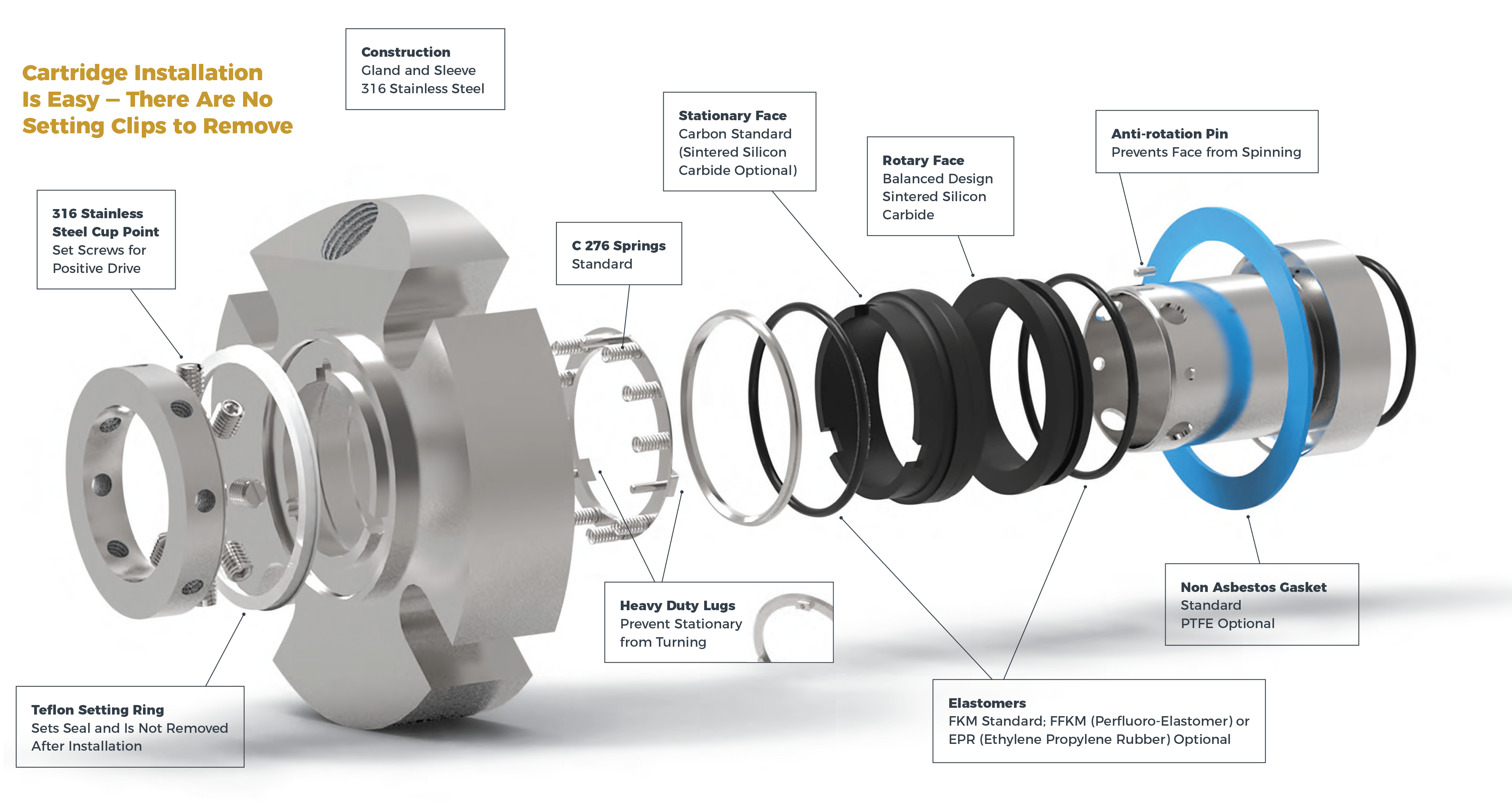
Cartridge-mounted, end-face seals were primarily introduced for installation on American National Standards Institute centrifugal pumps for making axial shaft adjustments. Their simplicity and ease of installation and maintenance makes cartridge-mounted single and dual units a strong choice for rotating equipment with a stuffing box or seal chamber in which a gland can be installed.
Air seals use a knife of air to seal the process instead of seal faces. They are primarily installed on rotating equipment used to move or mix powders, bulk solids, or heavy slurries.
One factor stands out as the primary cause of premature seal failure — application. This involves defining the conditions inside the seal chamber, which dictate how long and how well the seal performs. Once these conditions are known, the best seal design for the conditions should be selected.
Extending the life of end-face mechanical seals primarily depends on clean and cool operation, which is directly affected by the application.Misapplication of materials of construction is a common error that rapidly leads to premature seal failure. For example, process fluids that are sticky, such as glue, molasses, and paint, can bind the faces together.
Every application, process fluid, and change in the environment adds a new and often unconsidered mix of consequences, which is why the application has such a tremendous impact on seal reliability.
Once the seal design best for the application is selected, precision installation follows. Many seal failures occur because the personnel incorrectly installed the seal. If installing a component seal, an experienced technician should be the installer. Cartridge seals are simpler to install, but errors still occur. Follow the manufacturer’s instructions carefully. If external barrier fluid will be used, ensure that the environmental controls are set up correctly. Correct setup allows for the proper pressure of the barrier fluid into the stuffing box and adequate cooling of the fluid.
Many steps are required to carry out precision installation. The major steps for most cartridge mechanical seals are:Preinstallation check list (including equipment inspection and cleaning)
Inspect and empty the stuffing box, correcting any holes, burrs, or sharp edges and ensuring that adequate space is available to adequately fit the seal assembly
Defining how a mechanical seal will be used and its environment is critical for optimal operation and life. Often, seal environmental controls are over looked, resulting in shorter seal life. Even with the ideal design and precision installation, problems may arise. Any hostile operating conditions or changes in the process parameters can override the capabilities of the design and materials, thereby reducing reliability. To obtain optimal seal life, the seal should be operated and maintained as designed.
One example can be found in wastewater treatment plants where raw sewage must be moved with high-speed centrifugal pumps. These water-based solutions are entrained with solids that can hang up the seal and quickly erode the selected materials if the slurry migrates between the faces.
Flush water from an external source is a common solution for preventing premature failure. It floods the seal cavity with a clean, cool water. This flush must be maintained at a higher pressure than the wastewater because it provides a clean, cool environment that is essential for safeguarding the life of the mechanical seal. These single-seal systems operating properly will increase water consumption and will also dilute the pumped product.
In some facilities, water consumption may be a primary concern or process dilution cannot be tolerated. For these situations, a dual-seal system operating with an independent, clean-liquid flush will be required.
Other environmental factors, such as temperature and pressure, must also be carefully controlled to prevent leakage. Careful attention should be given to the environmental control systems specified for sealing hazardous or toxic fluids. They must meet the allowable leakage tolerances for the fluid being sealed and prevent excessive leakage in case a seal fails.
Mechanical seals prevent pumps from leaking by containing the pressure of the pumping process. They withstand the friction caused by the pump shaft rotating. This results in less wasted product, more cost savings, and less clean up.

Have a clean area available for the components and ensure that there are no finger prints, oil or grease on the primary seal faces. Wipe with alcohol using a lint free cloth if necessary.
Primary seal face flatness will have been confirmed by the seal manufacturer and should be within 1-2 helium light bands. For this reason, the primary seal faces must be free of fingerprints, oil and/or grease.
Clean and de-burr the shaft area and seal chamber area as required using a solvent that will be compatible with the process fluid. (Note: Assure all piping/tubing is isolated from flush/quench ports. Plastic plugs need to be installed in all flush/quench after isolation of piping/tubing, up to the point of the piping/tubing reinstallation.
Proper spring compression check (‘working height’) – obtain dimension from seal drawing which shows the distance between the back of the seal retainer and the seal chamber face. Then fit the bearing bracket and shaft up against the casing and mark (with bluing pen) the point on shaft or sleeve directly below the seal chamber face. Remove shaft bearing bracket from casing and mark the dimension where the back of the retainer sits when assembled.
Attach seal head to shaft/sleeve and ensure that set screws are installed on clean and undamaged shaft areas. If this is not possible, carefully de-burr with a file and smooth out with emery cloth.
Install the stationary seal face into gland evenly to ensure face is not cocked. Assure that any finger prints are removed with alcohol and lint free towel.
Install gland to stuffing box using opposite and even tightening technique. Prior to doing so, a sweep of the seal chamber face is required to ensure proper sealing between gasket/’O’ ring on seal gland and seal chamber. A dial indicator should be attached to the shaft and the shaft will be rotated to cover a complete sweep of the seal chamber face. TIR should be no more than 0.005’.
After seal is completely installed, conduct a static pressure check. Consult the seal vendor for the proper pressure if static limit is not indicated on seal drawing. If any leaks are observed, consult seal vendor immediately.
Contaminated faces – can affect face flatness, resulting in excessive leakage. In addition, certain oils can set-up like adhesives and pull material out of the carbon primary ring faces after start-up, resulting in pre-mature seal failures.
Not setting proper spring compression: excessive compression – more seal wear. Low compression – will not provide sufficient face contact during start-up and standby conditions allowing excessive leakage.
Improper installation of mating ring into the gland resulting in excessive leakage due to improper face contact. Note that if back of mating ring is visibly ‘not flat’, the same result can apply. Stuffing box face TIR should be checked with dial indicator on shaft. Seal chamber face flatness should be no more than 0.005’ TIR.
Installation of gland to stuffing box not using equal and opposite tightening technique. Failure to tighten the nuts/capscrews properly can cock the mating ring, which will not allow for proper contact between the faces and result in excessive leakage between the seal faces.
Assure seal chamber is isolated from all flush and quench connections systems. Plastic plugs need to be installed in all flush/quench after isolation of piping/tubing up to the point of the piping/tubing installation.
Install gland to seal chamber using equal and opposite tightening technique. Prior to doing so, a sweep of the seal chamber face is required to ensure proper sealing between gasket/’O’ ring on seal gland and seal chamber. A dial indicator should be attached to the shaft and the shaft will be rotated to cover a complete sweep of the seal chamber face. TIR should be no more than 0.005’.
Failure to have and implement a required mechanical seal installation procedure has been a principal cause of low mechanical seal MTBFs (lower than 12 months).
FAI has used this best practice since the 1990s to ensure that plant mechanical seal installation procedures are in complete accordance with mechanical seal vendors’ recommendations and to ensure optimum installed seal safety and reliability.

Proper installation of a mechanical seal is an important procedure in industries. For performing maintenance, the seal may have to be dismantled and reinstalled. The animation video describes a typical dismantling procedure of a mechanical seal.
The more common type of dynamic seal is the compression packing. They are easy to install and have low initial cost, but require more maintenance. They permit greater amount of leakage and may not comply with emission standards.
Mechanical Seals can greatly reduce product leakage and require lesser maintenance. However greater skill is required in mechanical seal installation and maintenance.
A pump which cavitates, has high vibration, or needs an overhaul rather than a seal change is not going to allow a seal to reach its design life of more than 3 yr of continuous service. To obtain maximum seal life, a pump and seal support system must be operating properly.
Modern mechanical seal designs can be extremely cost effective and reliable when installed on correctly sized and maintained pumps. While all of the conditions which must be considered to attain a minimal seal service life cannot be covered, there are typical problems that everyone encounters when installing seals.
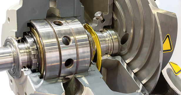
Mechanical seals are precision devices, with faces lapped within one micron flatness (Fig. 1). Seals can be very costly, and the installation procedure can determine how much of the dollar value spent is actually realized. With the increase in multicraft personnel doing seal installations, correct procedures become even more important to obtain reliability and value. Poor installation, even with newer cartridge seal designs, is still one of the major causes of short seal life and accounts for up to 20% of seal failures.
The old mechanical seal should be disassembled to determine the cause of failure, unless the causes are obvious. A few minutes taken here can dramatically improve the life of the next installation. Many times, old seals can be field repaired with a kit (Fig. 2). New seals may require installation of different O-ring compounds, based on the failure analysis.
Proper elastomer material choice is essential to seal operation. Temperature limits and chemical compatibility must be checked. Charts are available from seal and O-ring manufacturers. The O-ring selected must be correct for the products being sealed and any cleaners used to flush the system. Be careful to only use the O-ring lubricant supplied with the new seal.
O-ring damage can easily occur. Cutting or nicking is a common problem, especially when the O-ring is compressed in its groove and must slide over holes, snap-ring grooves, key-ways, slots, or threads. Ensure that all surfaces are properly deburred and feel smooth to the touch. It is sometimes possible to cover obstructions with thin tape or plastic wrap to ease installation.
Be certain that O-rings are in their proper position, in grooves or counterbores. Some seal designs have many steps, and the O-ring location may not be obvious. Refer to the installation instructions and drawings or photographs. Silicone grease can be used to keep the O-ring in place when it serves as a gasket. In these cases, a groove is usually machined into the seal gland.
The surface finish on which the secondary seal or O-ring must seal is very important. For a static surface, where there is no relative movement, a maximum of a 45 rms finish can be used. For dynamic surfaces a maximum of 32 rms should be present, and in applications where there is substantial axial movement a finish of 16 rms is preferable. The harder the O-ring durometer, the finer the finish required. Surfaces must be free from defects such as scratches, nicks, and burrs.
Teflon or Teflon encapsulated O-rings are stiff and easily damaged. Placing these O-rings in hot water softens them and facilitates installation. Lubricate them well before installation. Check the orientation of spring-energized Teflon seals because they are typically unidirectional.
Graphite secondary seals must be handled with care. They are fragile and easily damaged; O-rings can be twisted and stretched but graphite rings break. One factor to carefully control is the compression of graphite rings. Very often they are compressed in arrangements which use screws.
It is imperative that the loading be done uniformly to maintain squareness to the shaft on rotary parts and parallelism to the gland on stationary parts. A torque wrench and a dial indicator should be used to maintain squareness and parallelism within the limits specified by the seal manufacturer.
Installation instructions contain a wealth of information. Read the instructions before installing the seal and save the instructions for future reference. They can be useful when a problem arises.
When reassembling the seal, the instructions discuss, at length, a number of precautions to be observed; read and follow them. Don’t force components together; seal faces are easily damaged and expensive to replace. If a seal face or component is damaged it should not be installed.
Work on clean surfaces, with clean hands. Particulates can destroy a seal face in a few revolutions. Take the time to do the installation at a relaxed pace. Do not hurry, as this often leads to tearing the equipment down again.
Be careful when handling the seal, particularly the faces. If the seal is dropped, do not use it. Have the seal vendor check it out thoroughly. If parts do not go together, don’t force them. Measure, check drawings for orientation, and lubricate parts.
Don’t overtighten, which is probably one of the most common mistakes. Never use a “leverage enhancement” method. Wrenches and hex keys are designed for the average person to apply the proper amount of torque to a fastener. Two-bolt glands are easily overtorqued, which distorts stationary seal components and results in face leakage. Overtightening can damage the gasket or cause extrusion, which can also result in leakage.
When installing a noncartridge seal, be certain to use the stationary seal centering shims that are included. If the stationary seal face is not centered, the rotary face can run off of it, shortening seal lie.
Unfortunately, when leaks are encountered the natural tendency is to keep tightening. Instead, try loosening; it often works. The preferred method is to use a torque wrench correctly calibrated in in.-lb. Installation instructions give torque values for gland bolts, set screws, and socket head cap screws.
If there is doubt about anything not being correct, or the seal doesn’t feel right, it’s a good idea to call the manufacturer or the sales representative for help. The seal manufacturer wants to ensure your plant’s success with their product. Calling them two days after the seal started leaking doesn’t help anybody.
Once the seal is assembled, it should be tested. Dual seals are often tested with pressurized air and submerged in water. Seals designed for liquids may let some small bubbles escape past the faces. Slowly rising bubbles between faces are not a problem because liquids do not leak under these circumstances. Bubbles coming from O-rings, through a casting, welding, or a bellows, are not acceptable.
Test for face leakage by rotating the seal by hand. This method usually stops the leak. Put a few drops of water between the faces to verify the integrity of a liquid seal. Use distilled water because tap water leaves mineral residues on the faces once it evaporates. This approach is particularly important if the seal will be stored for several weeks prior to installation.
Although not specifically part of a seal installation, auxiliary equipment installation and placement can have a significant impact on seal performance. Most common problems relate to seal pots/ barrier fluid reservoirs, also referred to as convection tanks.
It is important to place them close to the seal, within 3-5 ft, and at least 1-ft above the seal. Use tubing fit with large radius bends as opposed to piping with a multitude of elbows and other connections. Keep the piping as simple as possible; the more complicated the piping to and from the seal, the poorer the flow of the barrier fluid.
Another common environmental control is a flush, introducing a clean liquid into the seal gland or stuffing box to extend seal life. If installing a flush, determine that it has at least 15-psi more pressure than the stuffing box, and ensure that the flush liquid is properly connected to the correct flush port.
Most balanced seal designs do not require a large volume of flushing; 5-8 gal./hr is normally all that is required for proper heat removal. Unbalanced seals require substantially higher flows. Install a flowmeter/rotometer to visually ensure the flush is entering the seal area (Fig. 3). The flush supply valve should be lockable in the open position.– Edited by Joseph L. Foszcz, Senior Editor, 630-320-7135, j.foszcz@cahners.com
The authors are available to answer questions about seal installation. Henri Azibert can be reached at 617-430-7000, ext. 6697. “Doc” Burke can be reached at 708-596-8400.

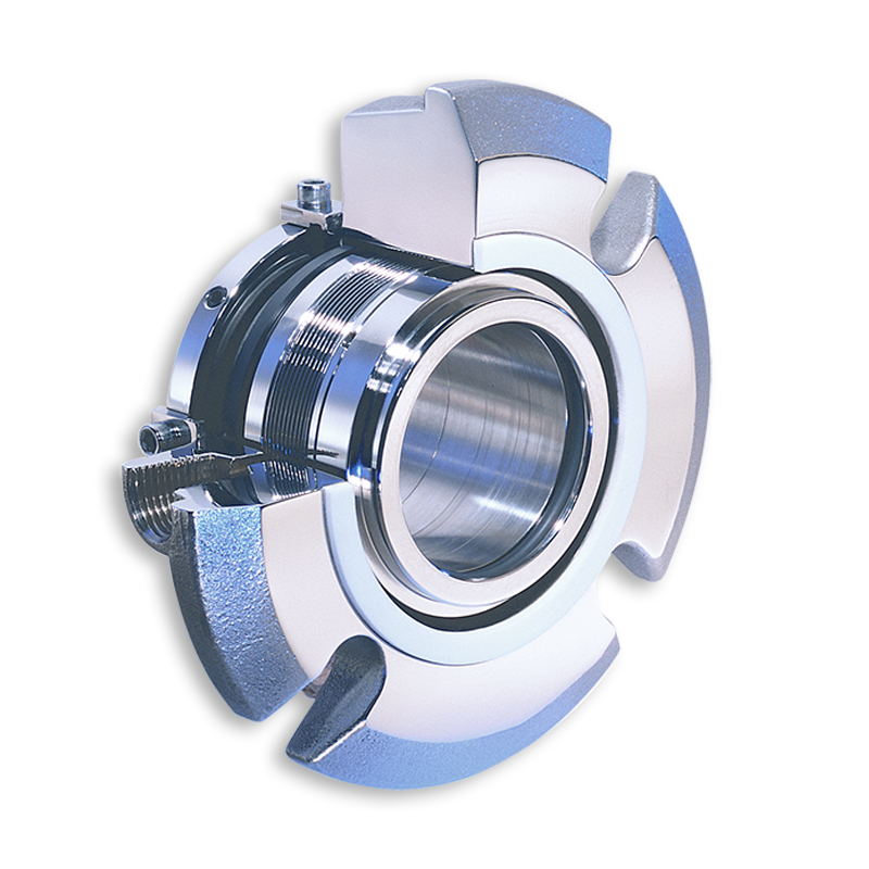
Our Mechanical Seals are used in a wide range of pumps and rotating equipment worldwide to prevent liquids and gases escaping into the environment. We manufacture mechanical seal types to suit all industries and our investment in modular design means that we provide the best on-time delivery performance in the industry.
The AESSEAL® range of seals, seal support systems and bearing protectors are all designed to improve pump reliability and reduce maintenance costs. Our business is built around giving our customers such exceptional service that they need never consider alternative sources of supply.
AESSEAL® operates from 235 locations in 104 countries, including 9 manufacturing and 44 repair locations, and has more than 300 customer service representatives who visit industrial plants every day. Find Out More..
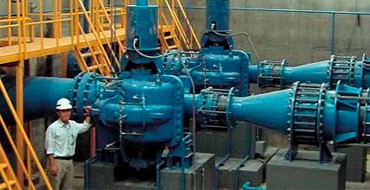
Power machines that have a rotating shaft, such as pumps and compressors, are generally known as “rotating machines.” Mechanical seals are a type of packing installed on the power transmitting shaft of a rotating machine. They are used in various applications ranging from automobiles, ships, rockets and industrial plant equipment, to residential devices.
Mechanical seals are intended to prevent the fluid (water or oil) used by a machine from leaking to the external environment (the atmosphere or a body of water). This role of mechanical seals contributes to the prevention of environmental contamination, energy saving through improved machine operating efficiency, and machine safety.
Shown below is a sectional view of a rotating machine that requires the installation of a mechanical seal. This machine has a large vessel and a rotating shaft at the center of the vessel (e.g., a mixer). The illustration shows the consequences of cases with and without a mechanical seal.
If the aim is solely to prevent leakage from the machine, it is effective to use a seal material known as gland packing on the shaft. However, a gland packing tightly wound around the shaft hinders the motion of the shaft, resulting in shaft wear and therefore requiring a lubricant during use.
To ensure this, each part is fabricated according to a precise design. Mechanical seals prevent leakage even with hazardous substances that are difficult to mechanically handle or under harsh conditions of high pressure and high rotating speed.
A mechanical seal is installed on the impeller rotating shaft. This prevents the liquid from leaking through the clearance between the pump body and the shaft.
The face materials where the stationary ring and the rotary ring rub against each other are the most important portions as a barrier to the fluid. If the clearance is too small, the friction increases, hindering the shaft motion or resulting in seal breakage. Conversely, if the clearance is too large, the liquid will leak. Consequently, it is necessary to control the clearance in the order of micrometers to prevent leakage, but at the same time ensuring lubrication by the fluid, thereby reducing the sliding torque and avoiding hindrance to the machines’ rotation.
The mechanical seal technology is a sum of mechanical engineering and physical property technology due to the above-mentioned functions and applications. More specifically, the core of the mechanical seal technology is the tribology (friction, wear and lubrication) technology used to control the surfaces where the stationary and rotary rings rub (slide) against each other.
Mechanical seals with improved functionality will not only prevent the liquid or gas handled by a machine from leaking to the outside, but also improve machine operating efficiency, thereby helping achieve energy saving and prevent environmental contamination. Moreover, in some cases, rotating machines handle media that, in the case of leakage, can lead to a dangerous accident. Therefore, mechanical seals are required to be highly reliable through manufacturing backed by solid engineering expertise.
These functions and roles will make mechanical seals increasingly important functional parts in the future. Their further technical innovation is anticipated. To positively respond to these expectations, Eagle Industry is working on technical research and development every day.
The mechanical seal technology was fundamentally established in the 1960s. Thereafter, it has been making significant progress by introducing various leading-edge technologies, and innovative mechanical seals created from the above advanced technology are continuously being put to practical use.
To meet the demands of the market sufficiently, an applicable range of the “pressure” and “rotation speed” of mechanical seals has been considerably extended since the beginning of the 2000s. This is due to advancing of the tribology technology such as to enhance a function of the sliding materials (e.g., composite material composition, coating technology) and/or a performance of the sliding surfaces based on the fluid lubrication theory (e.g., non-contact mechanical seal, surface textured mechanical seal). These advanced technologies are sustained by improvement in the element technology of numerical analysis, processing/production, physical property/composition analysis, measurement, verification test, and so on.
Installation method with the mechanical seal type, the different types of machines vary, but the installation is almost the same essentials, installation procedures and precautions are as follows:
(2) before loading the shaft (sleeve), the gland should be no burr, bearing in good condition; seals, shaft, sealed chamber, the gland should be cleaned. To reduce friction, the shaft is the site to install the mechanical seal coated with a thin layer of oil for lubrication, taking into account the rubber O-ring compatibility, if not oil, can be coated with soapy water. Float-mounted anti-static ring without the structure of reseller, not oiled, into the gland to be dry.
(4) operation before the first medium, the cooling water valve is open, check whether all the gas seal cavity drain to prevent the static pressure caused by leakage, and then start running.
A mechanical seal is simply a method of containing fluid within a vessel (typically pumps, mixers, etc.) where a rotating shaft passes through a stationary housing or occasionally, where the housing rotates around the shaft.
When sealing a centrifugal pump, the challenge is to allow a rotating shaft to enter the ‘wet’ area of the pump, without allowing large volumes of pressurized fluid to escape.
To address this challenge there needs to be a seal between the shaft and the pump housing that can contain the pressure of the process being pumped and withstand the friction caused by the shaft rotating.
Before examining how mechanical seals function it is important to understand other methods of forming this seal. One such method still widely used is Gland Packing.
The stationary part of the seal is fitted to the pump housing with a static seal –this may be sealed with an o-ring or gasket clamped between the stationary part and the pump housing.
The rotary portion of the seal is sealed onto the shaft usually with an O ring. This sealing point can also be regarded as static as this part of the seal rotates with the shaft.
One part of the seal, either to static or rotary portion, is always resiliently mounted and spring loaded to accommodate any small shaft deflections, shaft movement due to bearing tolerances and out-of-perpendicular alignment due to manufacturing tolerances.
The primary seal is essentially a spring loaded vertical bearing - consisting of two extremely flat faces, one fixed, one rotating, running against each other. The seal faces are pushed together using a combination of hydraulic force from the sealed fluid and spring force from the seal design. In this way a seal is formed to prevent process leaking between the rotating (shaft) and stationary areas of the pump.
If the seal faces rotated against each other without some form of lubrication they would wear and quickly fail due to face friction and heat generation. For this reason some form of lubrication is required between the rotary and stationary seal face; this is known as the fluid film
In most mechanical seals the faces are kept lubricated by maintaining a thin film of fluid between the seal faces. This film can either come from the process fluid being pumped or from an external source.
The need for a fluid film between the faces presents a design challenge – allowing sufficient lubricant to flow between the seal faces without the seal leaking an unacceptable amount of process fluid, or allowing contaminants in between the faces that could damage the seal itself.
This is achieved by maintaining a precise gap between the faces that is large enough to allow in a small amounts of clean lubricating liquid but small enough to prevent contaminants from entering the gap between the seal faces.
The gap between the faces on a typical seal is as little as 1 micron – 75 times narrower than a human hair. Because the gap is so tiny, particles that would otherwise damage the seal faces are unable to enter, and the amount of liquid that leaks through this space is so small that it appears as vapor – around ½ a teaspoon a day on a typical application.
This micro-gap is maintained using springs and hydraulic force to push the seal faces together, while the pressure of the liquid between the faces (the fluid film) acts to push them apart.
Without the pressure pushing them apart the two seal faces would be in full contact, this is known as dry running and would lead to rapid seal failure.
Without the process pressure (and the force of the springs) pushing the faces together the seal faces would separate too far, and allow fluid to leak out.
Mechanical seal engineering focuses on increasing the longevity of the primary seal faces by ensuring a high quality of lubricating fluid, and by selecting appropriate seal face materials for the process being pumped.
When we talk about leakage we are referring to visible leakage of the seal. This is because as detailed above, a very thin fluid film holds the two seal faces apart from each other. By maintaining a micro-gap a leak path is created making it impossible for a mechanical seal to be totally leak free. What we can say, however, is that unlike gland packing, the amount of leakage on a mechanical seal should be so low as to be visually undetectable.
4) ROTATIONAL DIRECTION: A pump shipped from the factory will NOT have the coupling spacer installed because you must first complete the driver rotational check. Additionally having the coupling removed helps in the process to set the impeller and seal. We have a 50% chance of guessing your local electrical phase rotation. If we are wrong, the pump becomes scrap metal.
As a matter of fact, the other OEMs state they have the same errors / issues with their end users not heeding the warnings on installation and startup.
Please note that if the impeller has “mated” with the casing there is a very high probability (99%) that the impeller will require replacement, repair and or rebalance, the casing will also require repair, and the shaft is now bent beyond specification, further the bearings and mechanical seal have been mechanically shocked.
![]()
The reliability of a mechanical seal depends on more than the design of the seal itself. It also depends heavily on the practices used to install the mechanical seal into the centrifugal pump or other equipment. The actual installation may occur in a controlled environment such as a factory or repair shop or it may occur out in the field in an installed pump. The people performing the installation range from skilled workers with significant experience with seals to general mechanics who have had little exposure to seals. Regardless of the situation, the steps taken during the installation process set the foundation for the ultimate success of the seal in operation.
Different pump and seal designs may require different installation procedures but there are several key elements that are common across all installations. These include inspection of the equipment, general requirements for equipment condition, preparation for installation, installing the seal, setting the seal drive, removal of setting/shipping fixtures, and connecting the piping plan. While each of the steps is deceptively simple, the ability to identify and correct problems during the installation is critical.


 8613371530291