
mechanical seal installation in stock
PumpWorks is the go-to company for all your pump sealing needs. The Sealing Technology Division of PumpWorks offers over 30 years of hands-on experience in the application, selection, troubleshooting, and repair of mechanical seals. We repair all manufactures of seals for a wide variety of applications from general industrial to process industries such as chemical, petroleum refining, and marine.
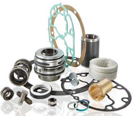
PumpWorks offers trained seal specialists and extensive in-house repair capabilities to service and repair all brands and types of seals including (but not limited to):
Before PumpWorks conducts a seal repair, we conduct a review of your equipment to isolate problem areas and to determine how to achieve long-term reliability with your seals. Our review consists of:
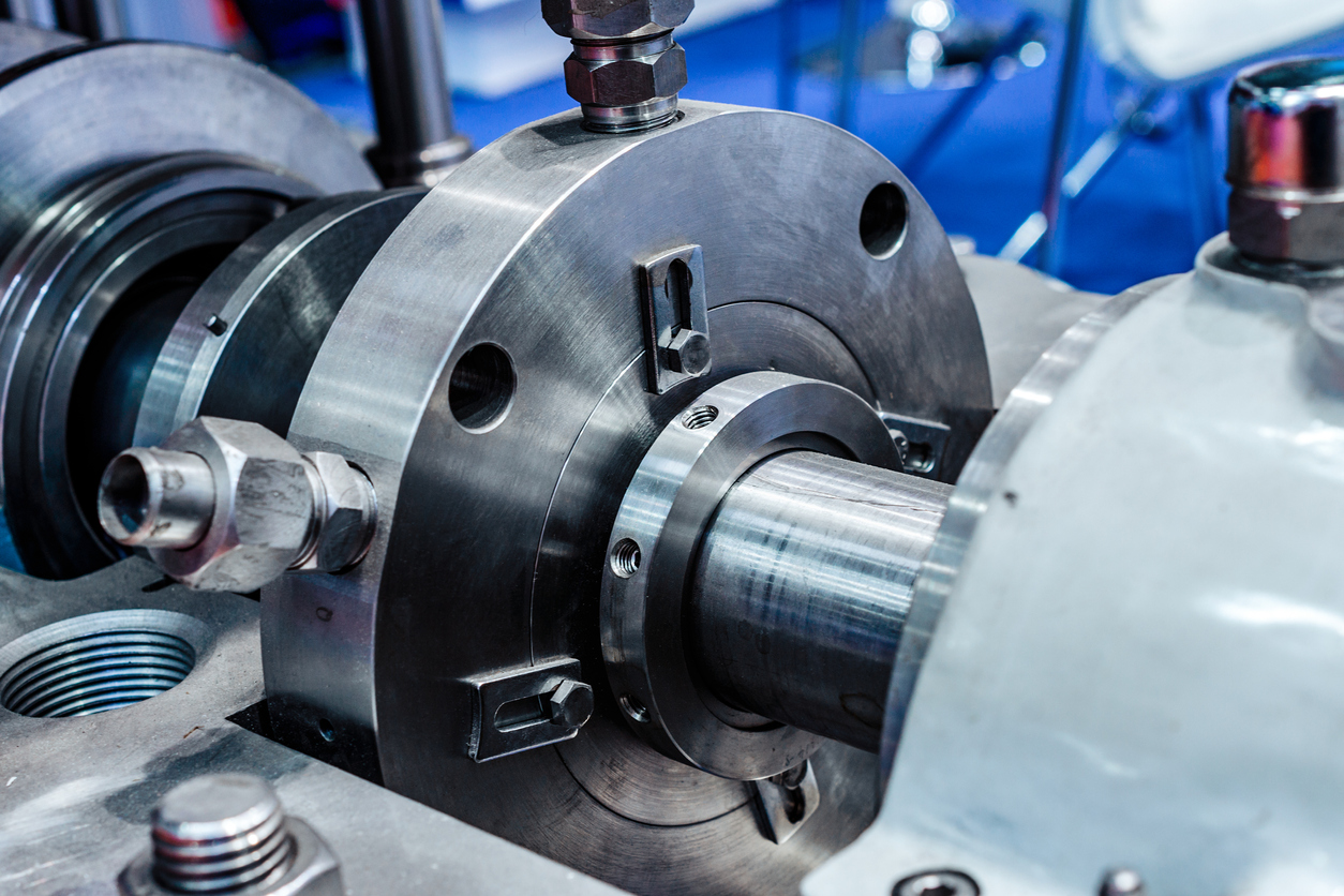
Once a seal is selected, our trained technicians can modify stuffing boxes, substitute component materials, re-install the seal and pressure test the entire pump. The mechanical seal can also be field installed to assure a positive fit and true alignment.

U.S Seal ozone and Salt Generators Seal Assembly, Size: 3/4 Inch Shaft, Viton Elastomers, Carbon Primary Ring, Polished Ceramic Seat, Stainless Steel Hardware, For Use With: Hayward Industries Max-Flo(TM), Super Pump(TM), Super Pump II(TM); American Products Americana(R), Bronze-Noryl; Pac-Fab AH Series; Premier Pumps 120T Series, 225/255 MKII, 300/325/355, 725/756; Purex-Hydrotech Hydropump(R), L-Series; Jacuzzi Magnum(R), RC-Series; Marlow Argonaut(R), Mardur(R); Wayne Water Systems

Three variables that most affect the design selection of mechanical seals are: equipmentcharacteristics, application and operating conditions, and the leak rate objective.
The first decision, however, rests in determining if one or multiple seals are required. This often has the potential for a devastating impact on overall performance and reliability.
Relatively clean process fluids with adequate lubricating properties can be contained with a single-seal arrangement. These seals are typically less expensive to install and simpler for teams to operate and maintain. If a separate lubrication system is required, a double seal arrangement will be needed. This will help ensure mechanical seal reliability.
The amount of leakage to atmosphere, which is dictated by the plant’s leak rate objectives and/or regulatory requirements, must be controlled by the seal design chosen. All end-face mechanical seals operating effectively on high-speed applications allow a small amount of vapor to pass through the primary seal interface. Average leakage will be in the 1-cc-per-day range, which is within acceptable tolerances of most process fluids.
Rotating equipmentis the primary application in which end-face mechanical seals can be cost effectively considered and applied. This equipment is used in processing gases, liquids, and slurries.
Cartridge-mounted, end-face seals were primarily introduced for installation on American National Standards Institute centrifugal pumps for making axial shaft adjustments. Their simplicity and ease of installation and maintenance makes cartridge-mounted single and dual units a strong choice for rotating equipment with a stuffing box or seal chamber in which a gland can be installed.
Air seals use a knife of air to seal the process instead of seal faces. They are primarily installed on rotating equipment used to move or mix powders, bulk solids, or heavy slurries.
One factor stands out as the primary cause of premature seal failure — application. This involves defining the conditions inside the seal chamber, which dictate how long and how well the seal performs. Once these conditions are known, the best seal design for the conditions should be selected.
Extending the life of end-face mechanical seals primarily depends on clean and cool operation, which is directly affected by the application.Misapplication of materials of construction is a common error that rapidly leads to premature seal failure. For example, process fluids that are sticky, such as glue, molasses, and paint, can bind the faces together.
Every application, process fluid, and change in the environment adds a new and often unconsidered mix of consequences, which is why the application has such a tremendous impact on seal reliability.
Once the seal design best for the application is selected, precision installation follows. Many seal failures occur because the personnel incorrectly installed the seal. If installing a component seal, an experienced technician should be the installer. Cartridge seals are simpler to install, but errors still occur. Follow the manufacturer’s instructions carefully. If external barrier fluid will be used, ensure that the environmental controls are set up correctly. Correct setup allows for the proper pressure of the barrier fluid into the stuffing box and adequate cooling of the fluid.
Many steps are required to carry out precision installation. The major steps for most cartridge mechanical seals are:Preinstallation check list (including equipment inspection and cleaning)
Inspect and empty the stuffing box, correcting any holes, burrs, or sharp edges and ensuring that adequate space is available to adequately fit the seal assembly
Defining how a mechanical seal will be used and its environment is critical for optimal operation and life. Often, seal environmental controls are over looked, resulting in shorter seal life. Even with the ideal design and precision installation, problems may arise. Any hostile operating conditions or changes in the process parameters can override the capabilities of the design and materials, thereby reducing reliability. To obtain optimal seal life, the seal should be operated and maintained as designed.
One example can be found in wastewater treatment plants where raw sewage must be moved with high-speed centrifugal pumps. These water-based solutions are entrained with solids that can hang up the seal and quickly erode the selected materials if the slurry migrates between the faces.
Flush water from an external source is a common solution for preventing premature failure. It floods the seal cavity with a clean, cool water. This flush must be maintained at a higher pressure than the wastewater because it provides a clean, cool environment that is essential for safeguarding the life of the mechanical seal. These single-seal systems operating properly will increase water consumption and will also dilute the pumped product.
In some facilities, water consumption may be a primary concern or process dilution cannot be tolerated. For these situations, a dual-seal system operating with an independent, clean-liquid flush will be required.
Other environmental factors, such as temperature and pressure, must also be carefully controlled to prevent leakage. Careful attention should be given to the environmental control systems specified for sealing hazardous or toxic fluids. They must meet the allowable leakage tolerances for the fluid being sealed and prevent excessive leakage in case a seal fails.
Mechanical seals prevent pumps from leaking by containing the pressure of the pumping process. They withstand the friction caused by the pump shaft rotating. This results in less wasted product, more cost savings, and less clean up.

An essential aspect of the design of a gas compressor is the mechanical seal. A mechanical seal minimizes or eliminates gas leakage at the interface between a rotating shaft and the stationary housing.
Choose the correct construction materials for the application. The materials selected must endure the temperature extremes, pressure differentials and be tolerant of the corrosive process gases of the specificgas compressor application. Additionally, the compressor sealing face materials must have proper resistance to friction, frictional heat, and resistance to wear. One of the various grades of mechanical carbon is often chosen for the sealing faces
All friction mechanical seals require some form of lubrication to cool and help seal the gases in the gas compressor. Pre-lubing the seal faces and cavities will best protect the components during start up and the first moments of operation. Waiting for thelube systemto get lubricant to all areas of the seal after start up can have a detrimental effect on the seal’s longevity.
The compressor sealing faces of a mechanical seal are pushed together by some form of spring system. Before assembling the seal onto the shaft, confirm that the spring system is freely working and not hung up by pressing gently against the primary ring assembly, taking caution to avoid direct contact with the sealing surface with your hand.
This tip is specific to Ro-Flo’s Single Face Mechanical Seal. Specifically,installing the sealonto the sliding vane compressor. Refer to the mechanical seal diagram below for the specific component names. The first step of the installation is sliding the mating ring into place. Due to the o-ring on the inside diameter of the mating ring, this is a snug fit, and some effort is required to slide it onto the shaft.
The sealing face of the mating ring is highly polished, providing the best sealing surface. It is vital that this face, where the carbon primary ring contacts it, does not get scratched, dinged, or left pitted due to corrosion from salty fingerprints.And here’s the tip: use the Locking Sleeve to push the mating ring down the shaft. This will keep the mating ring square to the shaft, preventing it from getting cocked and stuck, and keep your hands off the sealing face.
The PSS Shaft Seal is a mechanical face seal. The sealing surface is created between the flat surfaces of the rotating stainless-steel rotor and the stationary carbon flange. The stationary carbon flange is attached to the front side of the bellows with hose clamps, and the back end of the bellows fits over the stern tube and is secured with hose clamps. The stainless-steel rotor is fitted on the shaft in front of the carbon flange. The stainless-steel rotor compresses the bellows before the rotor is secured to the shaft with set screws. This compression (pre-load) maintains constant contact between the two flat faces of the stainless-steel rotor and carbon flange, allowing the PSS to compensate for the variable fore and aft movement due to propeller thrust. In addition, the carbon flange is over-bored to the shaft diameter allowing it to float around the shaft and thus compensate for most misalignment and vibration problems. The stainless-steel rotor is sealed to the shaft by two O-rings recessed into the collar"s bore. These O-rings rotate with the shaft and stainless-steel rotor and do not experience wear during operation.


 8613371530291